Note: Descriptions are shown in the official language in which they were submitted.
CA 02834839 2013-10-31
WO 2012/151405 PCT/US2012/036333
Title
[001] ENDOLUMINAL IMPLANTABLE SURFACES AND METHOD OF MAKING
THE SAME
Background of the Invention
[002] The invention relates to methods and apparatus for manufacturing
medical devices,
wherein the medical device has a surface treated to promote the migration of
endothelial cells.
[003] One problem of implantable endoluminal devices, along with other
revascularization
procedures, including bypass surgery and balloon angioplasty, is restenosis of
the artery. An
important factor contributing to this possible reocclusion at the site of
stent placement is injury
to, and loss of, the natural non-thrombogenic lining of the arterial lumen,
the endothelium. Loss
of the endothelium, exposing the thrombogenic arterial wall matrix proteins,
along with the
generally thrombogenic nature of prosthetic materials, initiates platelet
deposition and activation
of the coagulation cascade. Depending on a multitude of factors, such as
activity of the
fibrinolytic system, the use of anticoagulants, and the nature of the lesion
substrate, the result of
this process may range from a small mural to an occlusive thrombus. Secondly,
loss of the
endothelium at the interventional site may be critical to the development and
extent of eventual
intimal hyperplasia at the site. Accordingly, the present invention attempts
to solve these
problems, as well as others.
Summary of the Invention
[004] In one embodiment, a method of manufacturing an endoluminal
implantable surface is
presented. The method includes the steps of providing an endoluminal
implantable surface, stent,
or graft having an inner wall surface, an outer wall surface, and a wall
thickness between about 5
and about 75 microns, alternatively between about 10 and 60 microns, and
forming a pattern
design into the endoluminal implantable surface, stent, or graft. The method
further includes the
step of creating at least one groove in the inner surface of the intravascular
stent by applying a
laser machining method to the inner surface.
[005] In another embodiment, a method of manufacturing an endoluminal
implantable surface
is presented. The method includes the steps of providing an endoluminal
implantable surface,
stent, or graft having an inner wall surface and an outer wall surface, and
forming a pattern
design into the endoluminal implantable surface, stent, or graft. The method
further includes the
steps of pre-structuring at least one of the inner wall and the outer wall
surfaces by applying a
1
CA 02834839 2013-10-31
WO 2012/151405 PCMJS2012/036333
laser machining method to the at least one wall surface to create an image of
a desired pattern,
and vacuum depositing material over the image of the desired pattern to create
a patterned
surface overlying the at least one surface and including the desired pattern.
A wall thickness
including the patterned surface overlying the at least one surface measures
between about 5 and
about 75 microns, alternatively between about 10 and 60 microns.
[006] In a further embodiment, a method of manufacturing an endoluminal
implantable
surface, stent, or graft is presented. The method includes the steps of
providing an endoluminal
implantable surface, stent, or graft having an inner wall surface and an outer
wall surface, and
forming a pattern design into the endoluminal implantable surface, stent, or
graft. The method
further includes the steps of pre-structuring at least one of the inner wall
and the outer wall
surfaces by applying a photolithographic method to the at least one wall
surface to create an
image of a desired pattern, and vacuum depositing material over the image of
the desired pattern
to create a patterned surface overlying the at least one surface and including
the desired pattern.
A wall thickness including the patterned surface overlying the at least one
surface measures
between about 5 and about 75 microns.
[007] The methods for manufacturing intravascular stents and apparatuses
thereof, when
compared with presently known methods for manufacturing such stents, increase
the rate of
migration of endothelial cells upon the inner surface of the intravascular
stent.
Brief Description of the Figures
[008] FIG. 1 is a partial cross sectional perspective view of a portion of
an intravascular stent
embedded within an arterial wall of a patient.
[009] FIG. 2 is an exploded view of the outlined portion of FIG. 1 denoted
as FIG. 2.
[010] FIG. 3 is a partial cross-sectional, perspective view corresponding
to FIG. 1 after the
passage of time.
[011] FIG. 4 is an exploded view of the outlined portion of FIG. 3 denoted
as FIG. 4.
[012] FIG. 5 is a partial cross-sectional view of the stent and artery of
FIGS. 1 and 3 after a
further passage of time.
[013] FIG. 6 is an exploded view of the outlined portion of FIG. 5 denoted
as FIG. 6.
[014] FIG. 7 is a partial cross-sectional view of the stent and artery of
FIG. 5, taken along
lines 7-7 of FIG. 5, and illustrates rapid endothelialization resulting in a
thin neointimal layer
covering the stent.
2
CA 02834839 2013-10-31
WO 2012/151405 PCMJS2012/036333
[015] FIG. 8 is a plan view of an interior portion of an unexpanded
intravascular stent in
accordance with one embodiment.
[016] FIG. 9A is a side view of an embodiment of an intravascular stent;
FIG. 9B is an
enlarged view of region A in FIG. 9A; FIG. 9C is a schematic of the heat-
affected zones due to
long pulse laser machining; FIG. 9D is a schematic of the femto-second laser
machining without
heat-affected zones; and FIG. 9E is a flow chart of one embodiment for the
method of
manufacturing the stent.
[017] FIGS. 10-17 are various embodiments of an exploded view of a groove
taken along line
10-10 of FIG. 8, illustrating various cross-sectional configurations and
characteristics of various
embodiments of grooves in accordance with one embodiment.
[018] FIG. 18 is a plan view of an inner portion of an intravascular stent
as released from the
substrate in accordance with one embodiment.
[019] FIG. 19 is an exploded perspective view of a calendaring apparatus
for manufacturing
stents in accordance with one embodiment.
[020] FIG. 20 is a partial cross-sectional view of a stamping apparatus for
manufacturing
stents in accordance with one embodiment, looking down the longitudinal axis
of a mandrel;
[021] FIG. 21 is an exploded perspective view of an apparatus utilizing an
impression roller
to manufacturer stents in accordance with one embodiment.
[022] FIG. 22 is an exploded perspective view of an expanding mandrel
apparatus for
manufacturing stents in accordance with one embodiment.
[023] FIG. 23 is a partial cross-sectional view of the mandrel of FIG. 22,
taken along lines
21-21 of FIG. 22.
[024] FIG. 24 is an exploded perspective view of an apparatus utilizing a
tapered mandrel to
manufacture stents in accordance with one embodiment.
[025] FIG. 25A is an exploded perspective view of an apparatus utilizing a
chemical removal
method to manufacture stents in accordance with one embodiment; FIG. 25B
illustrates an
embodiment of a portion of the apparatus of FIG. 25A; and FIG. 25C illustrates
another
embodiment of a portion of the apparatus of FIG. 25A.
[026] FIG. 26A is an exploded perspective view of an apparatus utilizing
a rotating coaxial
light source to inscribe microgrooves inside an intact tubular stent in
accordance with one
embodiment; and FIG. 26B is an exploded perspective view of an apparatus
utilizing a rotating
3
CA 02834839 2013-10-31
WO 2012/151405 PCMJS2012/036333
mask and fixed light source to inscribe microgrooves inside an intact tubular
stent in accordance
with one embodiment.
[027] FIG. 27 is an exploded perspective view of an electric discharge
machining apparatus
for manufacturing stents in accordance with one embodiment.
[028] FIG. 28 is a plan view of an interior portion of an intravascular
stent in accordance with
one embodiment.
[029] FIG. 29 is an exploded perspective view of an apparatus utilizing a
laser and a
mirror/prism to inscribe microgrooves inside an intact tubular stent in
accordance with one
embodiment.
Detailed Description of the Preferred Embodiments
[030] With reference to FIGS. 1 and 2, an intravascular stent 200 is
illustrated being disposed
within an artery 290 in engagement with arterial wall 210. For illustrative
purposes only,
intravascular stent 200, shown in FIGS. 1-6 is a Palmaz 1 m balloon-expandable
stent, as is known
in the art, stent 200 having an inner surface 201 and an outer surface 202.
FIGS. 1 and 2
illustrate stent 200 shortly after it has been placed within artery 290, and
after stent 200 has been
embedded into arterial wall 210, as is known in the art. FIGS. 1 and 2
illustrate what may be
generally characterized as correct placement of an intravascular stent. Stent
200 preferably
includes a plurality of metal members, or struts, 203, which may be
manufactured of stainless
steel, or other metal materials, as is known in the art. As illustrated in
FIGS. 1 and 2, correct
placement of stent 200 results in tissue mounds 211 protruding between the
struts 203, after
struts 203 have been embedded in the arterial wall 210. Struts 203 also form
troughs, or linear
depressions, 204 in arterial wall 210. Dependent upon the degree of blockage
of artery 290, and
the type and amount of instrumentation utilized prior to placement of stent
200, the mounds of
tissue 211 may retain endothelial cells (not shown).
[031] With reference to FIGS. 3 and 4, after the passage of time, a thin
layer of thrombus 215
rapidly fills the depressions 204, and covers the inner surfaces 201 of stent
200. As seen in FIG.
4, the edges 216 of thrombus 215 feather toward the tissue mounds 211
protruding between the
struts 203. The endothelial cells which were retained on tissue mounds 211 can
provide for
reendothelialization of arterial wall 210.
[032] With reference to FIGS. 5 and 6, endothelial regeneration of artery
wall 210 proceeds
in a multicentric fashion, as illustrated by arrows 217, with the endothelial
cells migrating to, and
4
CA 02834839 2013-10-31
WO 2012/151405 PCMJS2012/036333
over, the struts 203 of stent 200 covered by thrombus 215. Assuming that the
stent 200 has been
properly implanted, or placed, as illustrated in FIGS. 1 and 2, the
satisfactory, rapid
endothelialization results in a thin tissue layer 218, as shown in FIG. 7. As
is known in the art, to
attain proper placement, or embedding, of stent 200, stent 200 must be
slightly overexpanded. In
the case of stent 200, which is a balloon-expandable stent, the balloon
diameter chosen for the
final expansion of stent 200 must be 10% to 15% larger than the matched
diameter of the artery,
or vessel, adjacent the site of implantation. As shown in FIG. 7, the diameter
Di of the lumen
219 of artery 290 is satisfactory. If the reendothelialization of artery wall
210 is impaired by
underexpansion of the stent or by excessive denudation of the arterial wall
prior to, or during,
stent placement, slower reendothelialization occurs. This results in increased
thrombus
deposition, proliferation of muscle cells, and a decreased luminal diameter
Di, due to the
formation of a thicker neointimal layer.
[033] With reference to FIG. 8, an intravascular stent 300 in accordance
with one
embodiment is illustrated. The intravascular stent, or stent, 300 has an inner
surface 301, and an
outer surface 302, outer surface 302 (See FIG. 1) normally being embedded into
the arterial wall
210 (See FIGS. 1-3, 5, and 7) in an abutting relationship. For illustrative
purposes only, the
structure of the intravascular stent 300 is illustrated as being a PalmazTM
balloon-expandable
stent, as is known in the art, illustrated in its initial, unexpanded
configuration. It should be
understood that the improvement of one embodiment is believed to be suitable
for use with any
intravascular stent, stent-grafts, grafts, heart valves, venous valves,
filters, occlusion devices,
catheters, steal implants, implantable contraceptives, implantable antitumor
pellets or rods,
shunts and patches, or other implantable medical devices having any
construction or made of any
material as will be hereinafter described. A medical device is an instrument,
apparatus, implant,
in vitro reagent, or other similar or related article, which is intended for
use in the diagnosis of
disease or other conditions, or in the cure, mitigation, treatment, or
prevention of disease, or
intended to affect the structure or any function of the body and which does
not achieve any of it's
primary intended purposes through chemical action within or on the body.
Similarly, the
improvement of the embodiments for the methods for manufacturing intravascular
stents is also
believed to be applicable to the manufacturing of any type of intravascular
medical device, stent-
grafts, grafts, heart valves, venous valves, filters, occlusion devices,
catheters, osteal implants,
implantable contraceptives, implantable antitumor pellets or rods, shunts and
patches,
5
CA 02834839 2013-10-31
WO 2012/151405 PCMJS2012/036333
pacemakers, medical wires or medical tubes for any type of medical device, or
other implantable
medical devices, as will also be hereinafter described. A pacemaker (or
artificial pacemaker, so
as not to be confused with the heart's natural pacemaker) is a medical device
that uses electrical
impulses, delivered by electrodes contacting the heart muscles, to regulate
the beating of the
heart. The electrodes may be covered by tubing or other material that includes
a surface that may
require endothelialization and grooves thereon.
[034] Referring to FIGS. 9A and 9B, in one embodiment, an intravascular
stent 350 consists
generally of a tubular cylindrical element having a stent wall that defines
the inner surface 301
and the outer surface 302 of the stent 350. The stent wall includes a wall
thickness measured
between the inner surface 301 and the outer surface 302. In one embodiment,
the wall thickness
includes at least one vacuum deposited layer of material. First structural
elements 310 are
distributed about the circumferential axis 314 of the stent 350 and extend
generally parallel to the
longitudinal axis 316 of the stent 350. The first structural elements 310 arc
connected as
described hereinbelow to a plurality 328 of the first structural elements 310.
Another plurality
338 of the first structural elements 310 is disposed longitudinally adjacent
to the plurality 328 of
the first structural elements 310. A plurality of second structural elements
312 interconnects
adjacent pairs of the pluralities of the first structural elements 310, for
example, the pluralities
328, 338 of the first structural elements 310.
[035] In this embodiment, each plurality of the first structural elements
310 has a generally
sinusoidal configuration with a plurality of peaks 310a and a plurality of
troughs 310b disposed
between adjacent first structural elements 310. The plurality of peaks 310a
and the plurality of
troughs 310b may have either regular or irregular periodicity along the
circumferential axis 314
of each of the pluralities of the first structural elements 310. Further, the
plurality of peaks 310a
and the plurality of troughs 310b may have either regular or irregular
periodicity longitudinally
along the pluralities of the first structural elements 310, for example,
longitudinally along the
pluralities 328, 338, etc.
[036] Alternatively, each of the pluralities of the first structural
elements 310 may have
regions of regular periodicity and regions of irregular periodicity along the
circumferential axis
314 thereof or longitudinally along the pluralities of the first structural
elements 310, for
example, longitudinally along the pluralities 328, 338, etc. In this
embodiment, each of the
plurality of second structural elements 312 preferably comprise linear
elements which
6
CA 02834839 2013-10-31
WO 2012/151405 PCMJS2012/036333
interconnect a peak 310a disposed between a pair of the first structural
elements 310 on a first
plurality, for example, the plurality 328 of the first structural elements
310, with a trough 310b
disposed between a pair of the first structural elements 310 on an adjacent
plurality, for example
the plurality 338 of the first structural elements 310. In other embodiments,
the first and second
structural elements 310, 312 may have shapes and/or configurations different
from those
described hereinabove with regard to FIGS. 9A and 9B, as desired, appropriate,
or suitable for a
particular application.
[037] The intravascular stent 300, 350 including the first and second
structural elements 310,
312 are preferably made of materials chosen for their biocompatibility,
material properties, i.e.,
tensile strength, yield strength, and their ease of deposition. Suitable
materials include those
selected from the group of materials consisting of elemental titanium,
vanadium, aluminum,
nickel, tantalum, zirconium, chromium, silver, gold, silicon, magnesium,
niobium, scandium,
platinum, cobalt, palladium, manganese, molybdenum, and alloys thereof, such
as zirconium-
titanium alloys, nitinol, and stainless steel, biocompatible polymers. A
polymer is a large
molecule (macromolecule) composed of repeating structural units. A plastic
material is any of a
wide range of synthetic or semi-synthetic organic solids that are moldable.
Plastics are typically
organic polymers of high molecular mass, but they often contain other
substances, which are
usually synthetic, most commonly derived from petrochemicals, but many are
partially natural.
Alternatively, the material may be any biodegradable material, natural or
synthetic, that may be
broken down by living organisms, including, but not limited to a biodegradable
organic
substance, biodegradable polymer substances (Poly(lactic acid) PLA, poly(L-
lactic acid)
(PLLA), poly(lactic-co-glycolic acid) PLGA, poly(glycolicacid) (PGA),
Polyethylene glycol,
PEG, polytetrafluoroethylene (PTFE), and the like), peptides or proteins,
carbohydrates, nucleic
acids, fatty acids, carbon-containing compounds, nanoparticles,
microparticles, biocomposites,
sol-gel coatings, hydrogels water-soluble bioactive agent and poly(alkyl
cyanoacrylate) polymer
coating; nanoparticle coating formed by electrospraying; a poly(diol citrates)-
based coatings;
natural biodegradable hydrophobic polysaccharides coatings, hydrophilic
polymers, and the like.
Alternatively, other materials may be used, such as gold, other metals,
heparin, silicon carbide,
titanium-nitride-oxide, phoshphorylcholine, and other medical device coatings.
[0381 Each of the first and second structural elements 310, 312 may be made
of the same
material or of different materials and have the same material properties or
have different material
7
properties. The term material properties is intended to encompass physical
properties, including
by way of example and not limitation, elasticity, tensile strength, mechanical
properties,
hardness, bulk and/or surface grain size, grain composition, grain boundary
size, and intra- and
inter-granular precipitates.
10391 Similarly, the materials selected for the first structural elements
310 and the second
structural elements 312 may be selected to have the same or different chemical
properties. The
term chemical properties is intended to encompass both any chemical reaction
and change of
state that the material may undergo after being implanted into a body and the
physiological
response of the body to the material after implantation.
[040] The intravascular stent 300, 350 is preferably made of a material
having controlled
heterogeneities on the inner surface 301 thereof. As described in commonly
assigned U.S. Patent
No. 6,379,383, issued April 30, 2002,
heterogeneities
are controlled by fabricating the material of the stent to have defined bulk
and/or surface grain
size, grain composition, grain boundary size, and chemical and intra- and
inter-granular
precipitates. The controlled heterogeneities allow for heightened laser
machining techniques on
the surface of the deposited film, whereby the surface of the deposited film
allows for a decrease
in heat-affected zones, slag, recast, and microstructure damages during laser
machining.
10411 The
characteristically desirable material properties of the intravascular stent
are: (a)
optimum mechanical properties consistent with or exceeding regulatory approval
criteria, (b)
minimization of defects, such as cracking or pin hole defects, (c) a fatigue
life of 400 million
cycles as measured by simulated accelerated testing, (d) corrosion and/or
corrosion-fatigue
resistance, (c) biocompatibility without having biologically significant
impurities in the material,
(f) a substantially non-frictional abluminal surface to facilitate atraumatic
vascular crossing and
tracking with transcatheter techniques for stent introduction, (g) radiopaque
at selected sites and
MRI compatible, (h) have a luminal surface which is optimized for surface
energy and
microtopography, (i) minimal manufacturing and material cost consistent with
achieving the
desired material properties, and (j) high process yields.
[0421 The
foregoing properties of the intravascular stent 300, 350 are achieved by
employing
vacuum deposition technologies such as vacuum deposition, ion-beam assisted
evaporative
deposition, and sputtering techniques. In ion-beam assisted evaporative
deposition, it is
preferable to employ dual and simultaneous thermal electron beam evaporation
with
8
CA 2834839 2018-11-09
CA 02834839 2013-10-31
WO 2012/151405 PCMJS2012/036333
simultaneous ion bombardment of the substrate using an inert gas, such as
argon, xenon,
nitrogen, or neon. Bombardment with an inert gas, such as argon, serves to
reduce void content
by increasing atomic packing density in the deposited material during
deposition. The reduced
void content in the deposited material allows the mechanical properties of
that deposited material
to be similar to the bulk material properties. Deposition rates of up to 20
nm/sec are achievable
using ion beam assisted evaporative deposition techniques.
[043] When sputtering techniques are employed, a 200-micron thick stainless
steel film may
be deposited within about four hours of deposition time. With the sputtering
technique, it is
preferable to employ a cylindrical sputtering target, a single circumferential
source that
concentrically surrounds the substrate that is held in a coaxial position
within the source.
Alternate deposition processes which may be employed to form the intravascular
stent are
cathodic arc and direct ion beam deposition. Planar magnetron sources or
targets may also be
employed. In diode sputtering, not all of the electrons escaping the target
contribute to the
ionized plasma glow area. The wasted electrons fly around the chamber causing
radiation and
other problems, for example, the heating of the target. A magnetron sputtering
source addresses
the electron problem by placing magnets behind, and sometimes, at the sides of
the target. These
magnets capture the escaping electrons and confine them to the immediate
vicinity of the target.
The ion current (density of ionized argon atoms hitting the target) is
increased by an order of
magnitude over conventional diode sputtering systems, resulting in faster
deposition rates at
lower pressure. The lower pressure in the chamber helps create a cleaner film.
Target
temperature is lower with magnetron sputtering enhancing the deposition of
high quality films.
[044] During vacuum deposition, the chamber pressure, the deposition
pressure and the partial
pressure of the process gases are controlled to optimize deposition of the
desired species onto the
substrate. Both the reactive and non-reactive gases are controlled and the
inert or non-reactive
gaseous species introduced into the deposition chamber are typically argon and
nitrogen. The
substrate may be either stationary or moveable, either rotated about its
longitudinal axis, or
moved longitudinally or radially relative to the longitudinal axis within the
reactor to facilitate
deposition of the material onto the substrate.
[045] The material is vacuum deposited as a film or layer onto the substrate
or onto a bulk
material. The substrate may be a metal tubular substrate, a sacrificial metal
tubular substrate, or a
reusable ceramic or glass substrate. In one embodiment, the intravascular
stent 300, 350 may
9
CA 02834839 2013-10-31
WO 2012/151405 PCMJS2012/036333
comprise one or more layers of vacuum deposited material formed into a self-
supporting
structure. In another embodiment, the intravascular stent 300, 350 includes a
bulk material, either
a bulk material alone or a bulk material covered by one or more layers of
vacuum deposited
biocompatible material. Any number of layers of vacuum deposited material may
be included as
desired, appropriate, or suitable for a particular application.
[046] Preferably, the wall thickness of the vacuum deposited metallic
thin film is about 5 to
about 75 pm, alternatively, between about 10 to about 60 gm. A sacrificial
layer of a material,
such as carbon or aluminum, may be deposited intermediate the substrate and
the intravascular
stent 300, 350. The sacrificial layer may be comprised of any coating that may
be selectively
dissolved or otherwise removed from the vacuum deposited metallic thin film
via chemical,
electrochemical, or mechanical means. In each of the preferred embodiments,
the intravascular
stent 300, 350 is fabricated by employing a vacuum deposition technique that
entails vacuum
depositing a stent-forming metal onto a substrate, wherein the wall thickness
of the deposited
stent-forming metal is about 5 to about 75 pm, alternatively, between about 10
to about 60 gm.
[047] The one or more layers of vacuum deposited material may have
thicknesses that are the
same or different as desired or appropriate. Each layer may have a thickness
in a range from
about 1 nanometer to about 75 micrometers, from about 1 nanometer to about 20
micrometers,
from about 1 nanometer to about 10 micrometers, from about 1 nanometer to
about 5
micrometers, or from about 1 nanometer to about 3 micrometers.
[048] The intravascular stent 300, 350 may be removed from the substrate
after stent
formation by any of a variety of methods. For example, the substrate may be
removed by
chemical means, such as etching or dissolution, by ablation, by machining, or
by ultrasonic
energy. Alternatively, the substrate may be removed by mechanical means due to
differences in
expansion coefficients of materials. The resulting intravascular stent 300,
350 may then be
subjected to post-deposition processing to modify the crystalline structure,
such as by annealing,
or to modify the surface topography, such as by etching to affect and control
heterogeneities on
the luminal surface of the stent.
[049] Incorporation of a stent pattern design can be accomplished using
laser machining
methods, including by way of example and not limitation, using a femto-second
laser, using an
excimer laser, using a Laser MicroJet (water assisted), laser assisted
chemical machining, fiber
laser chirped pulsed amplifiers, or other laser combinations.
Photolithographic methods coupled
CA 02834839 2013-10-31
WO 2012/151405 PCMJS2012/036333
with chemical, electrochemical, reactive ion etch (R1E) micro-machining
techniques, as
described hereinbelow with regard to FIGS. 25A-26B may be employed in-lieu of
a laser
machining method to machine stent pattern designs when appropriate. In one
embodiment, the
stent 300, 350 is patterned by a laser machining process or method employing a
femto-second
laser to create micron-sized structures without linear optical absorption of
the material that can
often lead to heat deposition, micro-cracks, and small collateral damage to
the surrounding area.
Laser assisted chemical machining may also include non-laser forms of light
sources, such as
superluminescent diodes (SLD), and the like. This technique can be described
as photo-catalytic
or photo-activated chemical machining using, for example, UV light as the
catalyst to
activate/initiate chemical reaction in exposed areas.
[050] During an exemplary laser machining process, the intravascular stent
300, 350 may be
held by a pneumatically controlled 3C collet system, with standard collet
sizes ranging from
0.5mm to 12mm. A femto-second laser, for example, is used to cut the pattern
design into the
stent 300, 350. The exemplary fcmto-second laser operates at a wavelength of
about 1552 nm, an
energy per pulse of between about 10 and 100 pJ +/- about 5%, an average power
of between
about 2.5 watts to 15 watts or about 7.5 watts, a pulse width of less than
about 1.0 picosecond
(ps), typically between about 200-950 femtoseconds (fs), a peak power greater
than about
50MW, a pulse damage threshold between about 1-5 J/cm2, no beam expansion, a
beam diameter
between about 4.5 mm +/- 10%and a repetition rate of about 100kHz to about
150kHz. The
material removal rate is approximately 30-50 nm/pulse and the maximum pulse
rate is between
100kHz-1MHz with a uniformity of cut dimension of 1%.
[051] Femtosecond lasers are lasers that emit optical pulses with aduration
well below 1 ps
(ultrashort pulses), i.e., in the domain of femtoseconds (1 fs = 10-15 s).
Femtosecond lasers may
include Bulk Lasers, Fiber Lasers, Dye Lasers, Semiconductor Lasers,
titanium¨sapphire lasers,
and the like. Passively mode-locked solid-state bulk lasers can emit high-
quality ultrashort pulses
with typical durations between 30 fs and 30 ps. Various diode-pumped lasers,
e.g. based on
neodymium-doped or ytterbium-doped gain media, operate in this regime, with
typical average
output powers between 100 mW and 1 W. Titanium¨sapphire lasers with advanced
dispersion
compensation are suitable for pulse durations below 10 fs and down to
approximately 5 fs. The
pulse repetition rate is between about 50 MHz and 500 MHz, even though there
are low
11
CA 02834839 2013-10-31
WO 2012/151405 PCMJS2012/036333
repetition rate versions with a few megahertz for higher pulse energies, and
also miniature lasers
with tens of gigahertz.
[052] Various types of ultrafast fiber lasers, which are also in most cases
passively mode-
locked, typically offer pulse durations between about 50 and 500 fs,
repetition rates between
about 10 and 100 MHz, and average powers of a few milliwatts. Substantially
higher average
powers and pulse energies are possible, e.g. with stretched-pulse fiber lasers
or with similar
lasers, or in combination with a fiber amplifier. Dye lasers include a gain
bandwidth that allows
for pulse durations of the order of 10 fs, and different laser dyes are
suitable for emission at
various wavelengths, often in the visible spectral range. Some mode-locked
diode lasers can
generate pulses with femtosecond durations. Directly at the laser output, the
pulses durations are
usually at least several hundred femtoseconds, but with external pulse
compression, much shorter
pulse durations can be achieved. Vertical external-cavity surface-emitting
lasers (VECSELs) can
be passively mode-lock, which can deliver a combination of short pulse
durations, high pulse
repetition rates, and sometimes high average output power. Other types of
femtosccond lasers are
color center lasers and free electron lasers, where the latter can be made to
emit femtosecond
pulses even in the form of X-rays.
[053] High precision, accurate, athermal cuts may be created on the stent
300, 350 using the
femto-second laser. Such cuts are achieved by using a granite super structure,
which provides
excellent thermal expansion and vibration damping characteristics. A powdery
residue results on
the stent 300, 350 after laser machining with the exemplary femto-second
laser. The residue is
easily removed from the surface of the cut using ultrasonic agitation or
similar means, which
creates easy post-laser cleaning without the need to mechanically polish the
stent 300, 350 or
additional post-processing steps as indicated below.
[054] Laser machining may be used to create features with high dimensional
accuracy and
precision in a vacuum deposited metallic stent, for example, the stent 300,
350, having a wall
thickness in the range of about 5 to about 75 m, alternatively, between about
10 and 60 Jim. In
one embodiment, the laser machining resolves 3 microns wide grooves using the
femto-second
laser, where the precision on the motion system is 0.5 microns (X and Y-
direction). Any of a
variety of patterns may be laser cut into the stent 300, 350. Referring to
FIG. 9B, by way of
example and not limitation, the plurality 328 of the first structural elements
310 distributed about
the circumferential axis 314 and having a generally sinusoidal configuration
with a plurality of
12
CA 02834839 2013-10-31
WO 2012/151405 PCMJS2012/036333
peaks 310a and troughs 310b may be formed using a laser machining method.
Additionally, laser
machining may be used to form the plurality of the second structural elements
312
interconnecting adjacent pairs of the pluralities of the first structural
elements 310, as illustrated
in FIG. 9B.
[055] The femto-second laser machines metal without leaving any appreciable
amount of
Heat-Affected Zones (HAZ) on the lateral surface, which is shown in FIG. 9C.
The HAZ gives
way to uneven cutting and cracks in the microstructure of the metal, which
also leaves a thermal
melt residue on the top surface. However, femto-second laser machines do not
leave any HAZ or
microstructure cracks due to the physics used by the femto-second lasers that
results in athermal
ablation, or cold ablation. After femto-second laser machining, a powdery
residue results on the
surface of the metal that is readily removed from the surface of the cut part
using ultra-sonic
agitation or similar means. The post-laser cleaning is without the need to
mechanical polishing or
processing, which is required with other lasers that leave a thermal melt
residue on the top
surface. The laser ablation features are clean and free of any slag or recast,
as shown in FIG. 9D.
[056] The grooves may be machined by the femto-second laser by using a
focusing lens and
altering the distance between the target and the workpiece, as such adjusting
the focal position,
adjusting the focal lens length, theoretical spot size or beam width, cutting
speed, and power
intensity of the laser. The focal position may be adjusted between about -2.5
to about 7 to alter
the width of the groove or kerf width (depth of the groove or cut). The width
of the groove may
also be adjusted by moving the focal position closer to the surface of the
metal and the width
may be the narrowest when focused exactly on the surface of the sample. The
depth of the
grooves may be adjusted the laser beam is focused on the sample surface. The
taper angle may
be adjusted by focusing the beam on the top surface and adjusting the focal
position between
about -0.8 and +0.8, whereby the taper angle may be between about 45 and 90
degrees. The focal
lens may be adjusted to be between about 20 and 200 mm. The power intensity
may be adjusted
between about 100 to 700 mW to provide wider grooves, increase the depths of
grooves, or
increase the aspect ratio of depth-to-width of the grooves. The depth may be
increased by
increasing the power intensity to be between about 100 nm and 70 gm. The
theoretical spot size
may be between approximately 5 and 100 gm, whereby the threshold-based
ablation is able to
produce features smaller than the spot size. As such, the measured kerf width
of the groove may
be between about 100 nm and 35 [tm.
13
CA 02834839 2013-10-31
WO 2012/151405 PCMJS2012/036333
[057] Continuous wave lasers ablate by way of a thermodynamic process of
localized heating
of the target lattice followed by a phase change or combustion. Femto-second
pulsed lasers
deliver tens of microJoules of energy between about 700-800 femtosecond
pulses. When focused
to a spot size from between about 30 microns down to the diffraction limit,
ultrafast lasers
generate high optical intensities. Preferably, ultrafast pulsed lasers include
a pulse width T less
than 5 picoseconds. Coupled with the high optical intensities is an electric
field capable of
initiating multi-photon ionization of the target. The photo-ionization leads
to plasma formation,
which is followed by electrostatic ejection of the target ions. The entire
process of the
ionization, plasma formation, and coulombic explosion must happen on a
timescale shorter than
the heat can diffuse beyond the volume of material being ablated.
[0581 Each pulse of the ultrafast laser removes a given amount of
material faster than the heat
generated can diffuse from that localized volume to the material nearby.
Picosecond and
nanosecond pulse lasers may initiate multi-photon ionization; however, the
longer pulses allow
the heat imparted by the laser to diffuse beyond the ablation volume and into
the lattice
surrounding the target. Heat diffusion into the metal creates thermal damage
and changes to the
microstructure such as Heat-Affected Zones (HAZ), melts areas, recast, slag,
or dross. Scanning
Electron Microscope (SEM), Energy-dispersive X-ray spectroscopy (EDX), and X-
ray
diffraction (XRD) may be used to assess microstructural changes, heat affected
zones, recast,
dross, or slag on the surface of the metal.
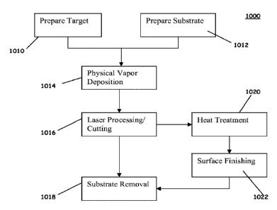
[059] As such, a diagram for laser machining the stent with thicknesses
between about 5 and
75 microns may be achieved by femtosecond lasers. FIG. 9E shows a flow chart
of the method
of manufacturing the stent 1000, starting with step 1010 of preparing the
target for deposition
and step 1012 of preparing the substrate for deposition as indicated above.
Step 1014 then
proceeds with physical vapor deposition of the tubular stent structure or any
other deposition
technique described above. Then step 1016 proceeds with laser processing or
machining the
tubular stent structure. With femtosecond laser machining techniques as
described above, the
substrate may be removed in step 1018 for substrate removal without any post-
processing steps.
Such post-processing steps are heat treatment 1020 and surface finishing 1022.
[0601 EXAMPLE 1
[0611 A pattern design was cut into a vacuum deposited metallic stent in an
unexpanded state
having a wall thickness of about 50pm using a femto-second laser. Referring to
FIGS. 9A and
14
CA 02834839 2013-10-31
WO 2012/151405 PCMJS2012/036333
9B, the pattern design included pluralities of the first structural elements
310 connected by a
plurality of the second structural elements 312, as described above. Use of
the femto-second
laser facilitated accurate and precise control of each of the dimensions, for
example, 310c, 312a,
318, 320, 322, 324, 326, 330, and 332 illustrated in FIGS. 9A and 9B.
[062] Such dimensions include, for example, widths 310c and 312a of the
first and second
structural elements 310 and 312, respectively, a length 318 of the first
structural element 310 less
a peak and trough, a peak-to-peak or trough-to-trough length 320 measured
along the
circumferential axis 314, a length 322 of a longitudinal interspacing between
adjacent pluralities
of the first structural elements 310, a length 324 measured longitudinally
from a peak of a first
one of the first structural elements to a peak of a second one of the first
structural elements 324,
wherein the first and second first structural elements 310 are disposed in
pluralities of the first
structural elements 310 separated by a plurality of the first structural
elements 310, a peak or
trough width 326, a length 330 of the stent 350, and a diameter 332 of the
stent 350.
[063] The aforementioned features were fabricated on the stent 350 in the
unexpanded state.
The above-noted dimensions had about the values indicated in Table 1
hereinbelow.
[064] Table 1. Exemplary sizes of laser cut elements of the stent 350 in
the unexpanded state
Element of the stent 350
Reference Number Dimension (about)(m)
Width of the first structural element 310 310c 29
Width of the second structural element 312 312a 29
Length of 310 less a peak and a trough 318 368
Peak to peak circumferential length 320 118
Longitudinal spacing between pluralities of 310 322 67
Peak to peak longitudinal spacing 324 1056
Width of peak or trough 326 35
Length of the stent 350 330 21000
Diameter of the stent 350 332 4250
[065] The intravascular stent pattern may be cut or machined in the
unexpanded configuration
followed by a post expansion to the intended diameter. Alternatively, the
intravascular stent
pattern may be cut or machined in the expanded state such that upon release
from the substrate,
the stent does not require further processing to achieve a target expanded
diameter.
[066] In accordance with one embodiment, the inner surface 301 of the stent
300 and the stent
350 (See FIG. 18) may be provided with at least one groove 400. If desired, as
will be
hereinafter described in greater detail, a plurality of grooves 400 could be
provided on, or in, the
inner surface 301 of the stent 300, 350. The use of the term "groove"
throughout this
CA 02834839 2013-10-31
WO 2012/151405 PCMJS2012/036333
specification and in the claims is intended to be construed as: a channel or
depression; a notch or
a V-shaped or rounded indentation; or a scratch, or a mark, having been made
with something
sharp or jagged. The at least one groove 400, or grooves, of one embodiment
may be provided
in, or on, the inner surface 301 of the stent 300 in any suitable manner, such
as by: abrading the
inner surface 301 to provide the at least one groove 400; a chemical or
mechanical etching
process; use of a laser or laser etching process; use of a diamond-tipped
tool; use of any suitable
abrasive material; or use of any tool or process, which can provide the
desired groove, or
grooves, 400 in, or on, the inner surface 301 of stent 300, 350, as will be
hereinafter described in
greater detail.
[067] As shown in FIG. 8, the at least one groove, or grooves, 400 may be
disposed with its
longitudinal axis 410 being disposed substantially parallel with the
longitudinal axis 305, 316 of
the stent 300, 350, respectively. Alternatively, the longitudinal axis 410 of
the at least one groove
400 may be disposed substantially perpendicular to the longitudinal axis 305,
316, as illustrated
by groove 400"; or the longitudinal axis 410 of the groove may be disposed at
an obtuse, or
acute, angle with respect to the longitudinal axis 305, 316, as illustrated by
groove 400'. The
angle that the groove 400' makes with respect to longitudinal axis 305, 316 is
either an acute or
an obtuse angle dependent upon from which direction the angle is measured with
respect to the
longitudinal axis 305, 316. For example, if the angle between the longitudinal
axis of the groove
400' and the longitudinal axis 305, 316 is measured as indicated by arrows A,
the angle is an
acute angle. If the angle is measured, as at arrows B, the angle is an obtuse
angle.
[068] Still with reference to FIG. 8, a plurality of the grooves 400 may
be provided on the
inner surface 301 of the stent 300, 350, two grooves 400 being shown for
illustrative purposes
only. Instead of a plurality of individual grooves, such as the grooves 400, a
single groove 400"
could be provided in a serpentine fashion, so as to cover as much of the inner
surface 301 of the
stent 300, 350 as desired. Similarly, the grooves could be provided in a cross-
hatched manner, or
pattern, as shown by the grooves 400". The grooves 400, 400', 400", 400", and
400" could be
provided alone or in combination with each other, as desired, to provide
whatever pattern of
grooves is desired, including a symmetrical, or an asymmetrical, pattern of
grooves. It should be
noted that the angular disposition and location of the various grooves 400-
400" will vary and be
altered upon the expansion of the stent 300, 350 within artery 201 (FIG. 1),
the stent 300 being
illustrated in its unexpanded configuration in FIG. 8. Similarly, if the stent
300, 350 were made
16
CA 02834839 2013-10-31
WO 2012/151405 PCMJS2012/036333
of wire or lengths of wire, the disposition and angular orientation of the
grooves formed on such
wire, or wire members, would similarly be altered upon the expansion and
implantation of such
stent. It should be further noted, as previously discussed, that the groove,
or grooves, may be
provided in, or on, the inner surface of any intravascular stent, for example,
the intravascular
stent 300, 350, so as to increase the rate of migration of endothelial cells
on, and over, the inner
surface of the intravascular stent 300, 350.
[069] With reference to FIGS. 10-17, various embodiments of the groove 400
will be
described in greater detail. In general, as seen in FIG.10, the groove 400 has
a width W, a depth
D, and a length L (See FIG. 8). The width W and depth D may be the same, and
not vary, along
the length L of the groove 400. Alternatively, the width W of the groove may
vary along the
length L of the groove 400. Alternatively, the depth D of the groove may vary
along the length L
of the at least one groove 400. Alternatively, both the width W and the depth
D of the groove
400 may vary along the length of the at least one groove. Similarly, as with
the location and
angular disposition of the groove, or grooves, 400 as described in connection
with FIG. 8, the
width W, depth D, and length L of the groove, or grooves, 400 can vary as
desired, and different
types and patterns of the grooves 400 could be disposed on the inner surface
301 of the stent 300,
350.
[070] As shown in FIGS. 10-17, the groove 400 may have a variety of
different cross-
sectional configurations. As desired, the cross-sectional configuration of the
groove, or grooves,
400 may vary along the length L of the groove; or the cross-sectional
configuration of the groove
400 may not vary along the length of the at least one groove 400. Similarly,
combinations of
such cross-sectional configurations for the grooves 400 could be utilized. The
cross-sectional
configuration of the groove, or grooves, 400 may be substantially symmetrical
about the
longitudinal axis 410 of the groove 400 as illustrated in FIGS. 8 and 10; or
the cross-sectional
configuration of the at least one groove 400 may be substantially asymmetrical
about the
longitudinal axis 410 of the least one groove 400, as illustrated in FIGS. 15
and 17. The cross-
sectional configurations of the groove 400 can assume a variety of shapes,
some of which are
illustrated in FIGS. 10-17, and include those cross-sectional configurations
which are
substantially: square shaped (FIG. 10); U shaped (FIG. 11); triangular, or V
shaped (FIG. 12);
rectangular shaped (FIG. 13); and triangular, or keyway shaped (FIG. 14). Wall
surface 303 of
each groove 400 may be substantially smooth, such as illustrated in FIGS. 10-
14, or the wall
17
CA 02834839 2013-10-31
WO 2012/151405 PCMJS2012/036333
surface 303 may be jagged, or roughened, as illustrated in FIGS. 15 and 17. As
illustrated in
FIG. 16, the wall surface 303 could also be provided with at least one
protrusion 304 and at least
one indentation 305 if desired, and additional protrusions and indentations
304, 305 could be
provided as desired.
[071] The depth D of the groove, or grooves, 400 may fall within a range of
approximately
one-half to approximately ten microns. However, it is preferable that the
depth D of the groove,
or grooves, 400 not exceed the distance between the inner surface 301 and the
outer surface 302
of the stent 300, 350. The width W of groove, or grooves, 400, may fall within
a range of
approximately two to approximately forty microns. Of course, the width W and
depth D could be
varied from the foregoing ranges, provided the rate of migration of
endothelial cells onto the
stent 300, 350 is not impaired. The length L of the groove 400 may extend the
entire length of
stent 300, 350, such as the groove 400 of FIG. 8; or the length L' of a groove
may be less than
the entire length of stent 300, such as the groove 400" in FIG. 8. The groove,
or grooves, 400 of
one embodiment may be continuous, or discontinuous, along inner surface 301 of
the stent 300,
350.
[072] The portion of the inner surface 301 of the stent 300, 350 which
has not been provided
with a groove, or grooves, 400 in accordance with one embodiment, may have any
suitable, or
desired, surface finish, such as an electropolished surface, as is known in
the art, or may be
provided with whatever surface finish or coating is desired. It is believed
that when at least one
groove in accordance with one embodiment is disposed, or provided, on, or in,
the inner surface
301 of the intravascular stent 300, 350, after the implantation of the stent
300, 350, the rate of
migration of endothelial cells upon the inner surface 301 will be increased
over that rate of
migration which would be obtained if the inner surface 301 were not provided
with the at least
one groove 400 in accordance with one embodiment.
[073] With reference to FIG. 18, the inner surface 301 of the intravascular
stent 300, 350 may
be inscribed with a grooved pattern by pre-structuring the surface of a
substrate onto which the
deposition takes place. Etching, photolithography techniques, mechanical
machining, and/or
laser machining methods, as described hereinbelow with regard to FIGS. 25A-26B
and 29, may
be applied to the substrate surface to create a positive or negative image of
a desired pattern.
Subsequently, material may be vacuum deposited over the image of the desired
pattern to create
the inner surface 301 of the deposited material including the desired pattern.
Photolithography
18
CA 02834839 2013-10-31
WO 2012/151405 PCMJS2012/036333
(or "optical lithography")(or "UV lithography") is a process used in
microfabrication to
selectively remove parts of a thin film or the bulk of a substrate. It uses
light to transfer a
geometric pattern from a photomask to a light-sensitive chemical
"photoresist", or simply
"resist," on the substrate. A series of chemical treatments then either
engraves the exposure
.. pattern into, or enables deposition of a new material in the desired
pattern upon, the material
underneath the photo resist.
[074] Alternatively, a mask or a set of masks, which are either stationary
or moveable relative
to the substrate, may be used to define the pattern of at least one groove
that is applied to the
substrate. Patterning may be employed to achieve complex finished geometries
of the resultant
stent 300, 350, both in the context of spatial orientation of the pattern, as
well as the material
thickness at different regions of the deposited film, such as by varying the
wall thickness of the
material over its length to thicken sections at proximal or distal ends of the
stent 300, 350 to
prevent flaring of the stent upon radial expansion of the stent.
[075] With reference to FIG. 19, a calendaring apparatus 450 is illustrated
forming at least
one groove 400 (not shown) on, or in, the inner surface 301 of stent blank
300. Calendaring
apparatus 450 includes at least one calendaring roller 451 and an inner
mandrel 452. Calendaring
roller 451 is provided with a bearing shaft 453 and a pinion gear 454, which
is driven by a gear
drive 455 and gear drive apparatus 456. Bearing shaft 453 is received in a
bearing block 457,
which has a groove 458 for receipt of bearing shaft 453. Bearing block 457
also includes a
bottom plate 459 and bearing block 457 is movable therein, in the direction
shown by arrows
460, as by slidably mating with slots 461 formed in bottom plate 459. Bearing
block 457 is
further provided with an opening, or bearing journal, 465 for rotatably
receiving mounting hub
466 disposed upon the end of mandrel 452. Calendaring roller is rotated in the
direction shown
by arrow 467 and bears against the outer surface 302 of stent blank 300, with
a force sufficient to
impart the groove pattern 468 formed on the outer surface of mandrel 452 to
the inner surface
301 of stent blank 300. Mandrel 452 will have a raised groove pattern 468 on
the outer surface of
mandrel 452, corresponding to the desired groove, or grooves, 400 to be formed
on, or in, the
inner surface 301 of stent 300. The raised groove pattern 468 of mandrel 452
must be hardened
sufficiently to enable the formation of many stents 300 without dulling the
groove pattern 468 of
mandrel 452. Mandrel 452 may have a working length corresponding to the length
of the stent
300 and an overall length longer than its working length, to permit the
receipt of mandrel
19
CA 02834839 2013-10-31
WO 2012/151405 PCT/1JS2012/036333
mounting hub 466 within bearing block 457 and mounting hub 466 within gear
drive apparatus
456.
[076] Still with reference to FIG. 19, the outer diameter of mandrel 452
is preferably equal to
the inner diameter of the stent 300 in its collapsed state. The groove pattern
468 may correspond
to the desired groove pattern of groove, or grooves, 400 to be formed on the
inner surface 301 of
stent 300 after stent 300 has been fully expanded. If the desired groove
pattern upon expansion
of stent 300 is to have the groove, or grooves 400 become parallel to each
other upon expansion
of the stent 300, along the longitudinal axis of the expanded stent 300,
groove pattern 468, or the
pre-expanded groove pattern, must have an orientation to obtain the desired
post expansion
groove pattern, after radial expansion of stent 300. Stent 300 may be pre-
expanded slightly to
facilitate its placement on the mandrel 452 in order to prevent scratching of
the stent 300.
Mandrel 452 may include an orientation mechanism, or pin 469 which mates with
a
corresponding notch 469' on stent blank 300, in order to insure proper
orientation of stent blank
300 with respect to mandrel 452. Stent 300 may be crimped circumferentially
around mandrel
452 after it has been properly oriented. The force to impart the desired
groove pattern 468 upon,
or in, the inner surface 301 of stent 300 is provided by calendaring roller
451.
[077] With reference to FIG. 20, an alternative structure is provided to
impart the desired
groove pattern in, or upon, the inner surface 301 of stent blank 300. In lieu
of calendaring roller
451, a punch press, or stamping apparatus, 470 may be utilized to force the
inner surface 301 of
stent 300 upon the groove pattern 468 of mandrel 452. Stamping apparatus 470
may include a
hydraulic cylinder 471 and hydraulic piston 472, attached to a stamping
segment 473. The inner
surface 474 of stamping segment 473 has a radius of curvature which matches
the outer radius of
curvature 475 of stent 300, when it is disposed upon mandrel 452. If desired,
a plurality of
stamping devices 470' may be disposed about the outer surface 302 of stent
300, or alternatively
a single stamping device 470 may be utilized, and stent 300 and mandrel 452
may be rotated to
orient the stent 300 beneath the stamping segment 473.
[078] With reference to FIG. 21, the desired grooves 400 may be formed on
the inner surface
301 of stent blank 300 by an impression roller 480 which serves as the inner
mandrel. Impression
roller 480 is supported at its ends by roller bearing block 481, similar in
construction to
previously described bearing block 457. Similarly, a gear drive, or drive gear
mechanism, 482
may be provided, which is also similar in construction to gear drive 455.
Impression roller 480
CA 02834839 2013-10-31
WO 2012/151405 PCMJS2012/036333
has a bearing shaft 483 at one end of impression roller 480, bearing shaft 483
being received by
an opening, or journal bearing, 484 in bearing block 481. The other end of
impression roller 480
may have a pinion gear 485 which is received within rotating ring gear 486 in
gear drive
mechanism 482. A backup housing, such as a two-part backup housing 487, 487'
may be
provided for fixedly securing stent blank 300 while impression roller 480 is
rotated within stent
blank 300 to impart groove pattern 468 formed on the exterior of impression
roller 480 to the
inner surface 301 of stent blank 300.
[079] With reference to FIGS. 22 and 23, an expanding mandrel apparatus 500
for forming
the desired at least one groove 400 on, or in, the inner surface 301 of stent
blank 300 is
illustrated. Expanding mandrel 501 is preferably formed of a plurality of
mating and tapered
segments 502 having the desired groove pattern 468 formed on the outer surface
503 of each
segment 502. Stent blank 300 is disposed upon expanding mandrel 501 in the
unexpanded
configuration of expanding mandrel 501, stent blank 300 being oriented with
respect to mandrel
501, as by the previously described notch 469' and pin 469. A backup housing
487 and 487, as
previously described in connection with FIG. 21, may be utilized to retain
stent blank 300 while
expanding mandrel 501 is expanded outwardly to impart the desired groove
pattern 468 upon, or
in, the inner surface 301 of stent blank 300. In this regard, expanding
mandrel 501 is provided
with a tapered interior piston 505, which upon movement in the direction of
arrow 506 forces
mandrel segments 502 outwardly to assume their desired expanded configuration,
which forces
groove pattern 468 on mandrel 501 against the inner surface 301 of stent blank
300. 0-rings 507
may be utilized to secure stent 300 upon mandrel 501.
[080] With reference to FIG. 24, a tapered mandrel groove forming apparatus
530 is
illustrated. Tapered mandrel 531 is supported by a mandrel support bracket, or
other suitable
structure, 532 to fixedly secure tapered mandrel 531 as shown in FIG. 24. The
end 533 of
tapered mandrel 531, has a plurality of cutting teeth 534 disposed thereon.
The cutting teeth 534
may be abrasive particles, such as diamond chips, or tungsten carbide
particles or chips, which
are secured to tapered mandrel 531 in any suitable manner, and the cutting
teeth 534 form the
desired groove, or grooves, 400 on, or in, the inner surface 301 of stent
blank 300. Alternatively,
instead of cutting teeth 534, the outer surface 535 of tapered mandrel 531
could be provided with
a surface comparable to that formed on a metal cutting file or rasp, and the
file, or rasp, profile
would form the desired grooves 400. A stent holding fixture 537 is provided to
support stent
21
blank 300 in any desired manner, and the stent holding fixture 367 may be
provided with a piston
cylinder mechanism, 368, 369 to provide relative movement of stent 300 with
respect to tapered
mandrel 531. Alternatively, stent 300 can be fixed, and a suitable mechanism
can be provided to
move tapered mandrel 531 into and along the inner surface 301 of stent 300.
Preferably, stent
300 is in its expanded configuration.
[0811 With reference to FIGS. 25A, 25B and 25C, a photolithographic method
and apparatus
600 for forming the desired groove, or grooves, 400 on, or in, the interior
surface 301 of stent
blank 300 is illustrated. A stent holding fixture 601 is provided, and holding
fixture 601 may be
similar in construction to that of stent holding fixture 367 of FIG. 24.
Again, stent blank 300 is
provided with an orientation notch, or locator slot, 469'. A photo mask 602 is
formed from a
material such as Mylar* film. The dimensions of the mask, 602 correspond to
the inner surface
area of the inner surface 301 of stent 300. The mask 602 is formed into a
cylindrical orientation
to form a mask sleeve 603, which is wrapped onto a deflated balloon 605, such
as a balloon of a
conventional balloon angioplasty catheter. A conventional photoresist material
is spin coated
onto the inner surface 301 of stent blank 300. The mask sleeve 603, disposed
upon balloon 605 is
inserted into stent 300, and balloon 605 is expanded to force the mask sleeve
603 into an abutting
relationship with the photoresist coated inner surface 301 of stent 300.
Balloon 605 may be
provided with an orientation pin 606 which corresponds with an orientation
notch 607 on mask
sleeve 603, which in turn is also aligned with locator slot 469' on stent
blank 300. The expansion
of balloon 605 is sufficient to sandwich mask sleeve 603 into abutting contact
with the
photoresist coated inner surface 301 of stent 300; however, the balloon 605 is
not inflated
enough to squeeze the photoresist material off the stent 300. The interior
surface 301 of stent 300
is then irradiated through the inside of the balloon 605 through the balloon
wall, as by a suitable
light source 610. Balloon 605 is then deflated and mask sleeve 603 is removed
from the interior
.. of stent 300. The non-polymerized photoresist material is rinsed off and
the polymerized resist
material is hard baked upon the interior of stent 300. The groove, or grooves
400 are then
chemically etched into the non-protected metal surface on the interior surface
301 of stent 300.
The baked photoresist material is then removed by either conventional chemical
or mechanical
techniques.
10821 Alternatively, instead of using a Mylar sheet as a mask 602 to form
mask sleeve 603,
mask 602 may be formed directly upon the outer surface of balloon 605, as
shown in FIG. 25B.
Trademark*
22
CA 2834839 2018-11-09
CA 02834839 2013-10-31
WO 2012/151405 PCMJS2012/036333
The production of mask 602 directly upon the balloon outer surface can be
accomplished by
physically adhering the mask 602 onto the outer surface of balloon 605, or by
forming the mask
602 onto the surface of balloon 605 by deposition of the desired groove
pattern 468 by
deposition of UV absorbing material by thin film methods. In the case of
utilizing mask sleeve
603 as shown in FIG. 25C, the balloon material must be compliant enough so as
to prevent
creases from the balloon wall which may shadow the resulting mask 602. In the
case of mask
602 being formed on balloon 605 as shown in FIG. 25B, a non-compliant balloon
605 should be
used, so as not to distort the resulting image by the stretching of the
compliant balloon wall. If on
the other hand, the mask 602 is physically adhered to the outer wall of
balloon 605, a compliant
balloon 605 may be used provided the mask 602 is adhered to the balloon 605
when the balloon
605 is in its fully expanded diameter.
[083] With reference to FIGS. 26A and 26B, a method is shown for creating
grooves inside
an intact tubular stent 300, which involves casting patterned light inside a
stent 300 previously
coated with photosensitive material as discussed, for example, in connection
with FIG. 25A
(PSM). The light exposed areas are subjected to chemical etching to produce
the grooved pattern.
This method involves using a coaxial light source 800 with multiple small
beams 801 of light in
a single plane. The light source 800 could be displaced along the longitudinal
axis of the tube, or
stent 300, at a rate consistent with adequate exposure of the photosensitive
material. Computer
driven stepper motors could be utilized to drive the light source
longitudinally and/or radially,
which would allow for interlacing grooves (see FIG. 26A). One pass could
create 1 mm spacing,
while the next pass creates 500 um, and so on.
[084] Rotational movements could introduce variability in the groove
direction for zig-zag,
spiral or undulating patterns. Alternatively, the light source 800 could be
fixed as shown in FIG.
26B, and the beams would be as narrow and long as the grooves needed on the
inner surface of
the mask 602. Stepping of the mask 602 would allow narrow spacing of the
grooves.
[085] With reference to FIG. 27, an EDM process and apparatus 700 provide
the desired
groove, or grooves, 400 upon the interior 301 of stent 300. A non-conductive
stent alignment and
holding fixture 701, 701', similar in construction to backup housings 487,
487', previously
described, are provided for holding stent like blank 300. A bearing block
assembly 702, similar
to bearing block assembly 481 of FIG. 21, is provided along with an indexing
and current
transfer disk 703 provided within a drive gear mechanism 704, which is similar
in construction to
23
CA 02834839 2013-10-31
WO 2012/151405 PCMJS2012/036333
drive gear mechanisms 482 and 455, previously described in connection with
FIGS. 21 and 19.
An electric discharge machining ("EDM") electrode 710 having bearing shafts
711, 712,
disposed at its ends, for cooperation with bearing block assembly 702 and disk
703, respectively,
is rotated within stent blank 300. Current is provided to the raised surfaces,
or groove pattern,
.. 468, of electrode 710 to cut the desired groove, or grooves 400 into the
inner surface 301 of stent
300.
[086] With reference to FIG. 28, in one embodiment, a laser machining
process provides the
desired groove, or grooves, 400 upon the inner surface 301 of the stent 300,
350. In this
embodiment of the laser machining process, the intravaseular stent 300, 350 is
held by a
pneumatically controlled 3C collet system. A femto-second laser is preferably
used to provide
the at least one groove, or grooves, 400 on the stent 300, 350.
[087] With reference to FIG. 29, in another embodiment of a laser machining
process, a
laser 900 and mirror/prism 902 system provides the desired at least one
groove, or grooves, 400
upon the inner surface 301 of the stent 300, 350. In this embodiment, a non-
conductive stent
.. alignment and holding fixture, similar in construction to backup housings
487 previously
described in regard to FIGS. 21-23 and 27, is provided for holding stent like
blank 908. The
laser 900 is positioned at a proximal end 906 of the blank 908 such that a
laser beam 904 is
directed, along a longitudinal axis 912 of the blank 908, through the inner
diameter of the blank
908. The mirror/prism 902 is positioned at a distal end 910 of the blank 908.
The laser 900 is
aligned with the mirror/prism 902 in order to redirect the laser beam 904 to
cut at about 90 from
the longitudinal axis 912 of the blank 908 so that the laser beam 904 is
focused on the inner
surface 301 of the blank 908.
[088] In one embodiment, the blank 908 may be stationary and patterned with
at least one
groove, or grooves, 400 by having the mirror/prism 902 move linearly along the
longitudinal axis
912 and/or rotate circumferentially about the longitudinal axis 912. The
mirror/prism 902 could
be displaced along the longitudinal axis 912 of the blank 908 at a rate
suitable for adequate
exposure of the inner surface 301 to the laser beam 904. Computer driven
stepper motors could
be utilized to drive the mirror/prism axially along and radially perpendicular
to the longitudinal
axis 912 of the blank 908, which could allow for interlacing grooves. One pass
could create 1
mm spacing, while the next pass creates 500m, and so on.
24
CA 02834839 2013-10-31
WO 2012/151405 PCT/1JS2012/036333
[089] In another embodiment, the blank 908 can be staged on a programmable
linear slide
with rotational (also programmable) capability. In this embodiment, with
controlled slide and
rotation, the blank 908 can be moved along the longitudinal axis 912 over the
mirror/prism 902
and rotated around the mirror/prism 902 in order to create the desired at
least one groove, or
grooves, 400 on the inner surface 301 of the blank 908. Computer driven
stepper motors could be
utilized to drive the blank 908 axially along and radially perpendicular to
the longitudinal axis
912 of the blank 908. Rotational movements could introduce variability in the
groove direction
for zig-zag, spiral, or undulating patterns.
[090] Improved methods for creating a design pattern for a stent and for
creating a pattern of
grooves on an inner surface of the stent are presented. The methods include
etching,
photolithography techniques, mechanical machining, and laser machining. A
femto-second laser
method can produce a design pattern with high dimensional accuracy and
precision in a vacuum
deposited metallic stent having a wall thickness in the range of about 5 to
about 75)m,
alternatively, between about 10 to about 60 !um.
[091] While the present invention has been described with reference to its
preferred
embodiments, those of ordinary skill in the art will understand and appreciate
that variations in
materials, dimensions, geometries, and fabrication methods may be or become
known in the art,
yet still remain within the scope of the present invention which is limited
only by the claims
appended hereto. It is understood, therefore, that this disclosure is not
limited to the particular
embodiments disclosed, but it is intended to cover modifications that may
include a combination
of features illustrated in one or more embodiments with features illustrated
in any other
embodiments. Various modifications, equivalent processes, as well as numerous
structures to
which the present disclosure may be applicable will be readily apparent to
those of skill in the art
to which the present disclosure is directed upon review of the present
specification. Accordingly,
this description is to be construed as illustrative only and is presented for
the purpose of enabling
those skilled in the art to make and use the endoluminal implantable surface,
stent, or grafts
described herein and to teach the best mode of carrying out the same.