Note: Descriptions are shown in the official language in which they were submitted.
= CA 02835230 2013-11-05
Wind turbine rotor blade and method for installing a wind turbine
rotor blade
The present invention concerns a wind power installation rotor blade
and a method of fitting a wind power installation rotor blade.
Various technologies are known for fitting and removing rotor blades.
Typically the rotor blade is fitted and removed by means of a crane. For
that purpose handling means or slings are provided in the region near the
rotor blade root and in the region of the rotor blade tip. Those slings are
then fixed to a crane hook to be able to convey the rotor blade.
Alternatively a method of fitting rotor blades is also known, in which the
rotor blades have one or more two through holes which serve to receive
handling means. In the known methods of fitting and removing rotor
blades of a wind power installation the rotor blade is typically fitted or
removed in a vertically oriented position.
DE 20 2010 002 679 U1 shows a rotor blade of a wind power
installation with an arcuate deflection member for deflecting a cable for
fitting the rotor blade.
DE 103 05 543 Al shows a rotor blade of a wind power installation
with a through hole for fitting the rotor blade.
The object of the present invention is to provide a wind power
installation rotor blade which permits improved fitment and removal.
That object is attained by a wind power installation rotor blade
according to claim 1 and by a method according to claim 8.
Thus there is provided a wind power installation rotor blade having a
rotor blade root, a rotor blade tip, a rotor blade leading edge, a rotor blade
trailing edge, a pressure side and a suction side. The rotor blade further
has a rotor blade outer casing with at least one opening in the pressure
and/or suction side for receiving handling means for fitting or removing the
rotor blade. The rotor blade also has at least one fixing unit for fixing the
handling means which are introduced through the at least one opening.
The fixing unit is arranged in the interior of the rotor blade outer casing
between the pressure side and the suction side.
= CA 02835230 2013-11-05
=
2
According to an aspect of the invention a first end of the introduced
handling means is fixed at a first end of the fixing unit for example by
means of a bolt. The first end of the fixing unit is fixed to the side of the
rotor blade, that is opposite to the opening.
In an aspect of the invention there are provided at least three
openings in the rotor blade outer casing around the region of the centre of
gravity of the rotor blade.
In an aspect of the invention the handling means represent soft
slings for example of GRP or CRP.
In a further aspect of the invention the opening is closable from the
interior after fitment of the rotor blade has been effected.
In a further aspect of the invention the rotor blade outer casing, in
the region of the at least one opening and the fixing units, is of such a
large
size that a man can creep therethrough.
In a further aspect of the invention the fixing unit has a first and a
second end, wherein provided at the first end and the second end is a
respective reinforcing plate which is bonded from the interior in or to the
pressure side or the suction side.
In a further aspect of the invention the fixing unit is of a symmetrical
configuration and has a first and a second hole which are suitable for
receiving a bolt for fixing an end of the handling means.
The invention further concerns a method of fitting wind power
installation rotor blades. In this case a first rotor blade is lifted to the
pod
of the wind power installation by means of a crane and a handling means,
for example three handling means, which according to the invention are
fixed to the fixing unit within the rotor blade. Then the rotor blade is
fitted
to the pod and the rotor blade is lowered, wherein the three slings are still
fixed to the crane hook. In the lowered condition the rotor blade is still
held by the crane. A second rotor blade can then be lifted to the pod by
means of a second crane and fitted there. It is only after the second rotor
blade has been completely fitted that the handling means in the first rotor
blade are removed.
= = CA 02835230 2013-11-05
3
The invention concerns the notion of fitting or removing in particular
= larger rotor blades no longer in a vertically oriented position but in a
horizontally oriented position. That is advantageous because the surface
area on which the wind can act is reduced. The invention further concerns
the idea of being able to release the handling means required for fitting the
rotor blades, without a fitter having to negotiate the fitted rotor blade,
from
the outside, which for example can be effected by means of a man basket
on a crane. Rather the invention concerns the idea of so fixing the
handling means in the interior of the rotor blade that the they can also be
removed again in the interior of the blade. That can be effected for
example by a bolt which can be removed after fitment of the rotor blade
has been effected. Then the handling means (for example slings) can be
removed through the opening. None of the fitters has to go to the outside
of the rotor blade for that purpose. The fixing unit for fixing the introduced
handling means is preferably so adapted that it extends from the pressure
side to the suction side of the rotor blade.
Further configurations of the invention are subject-matter of the
appendant claims.
Advantages and embodiments by way of example of the invention
are described in greater detail hereinafter with reference to the drawing.
Figure 1 shows a diagrammatic plan view of a wind power installation
rotor blade according to a first embodiment,
Figure 2 shows a diagrammatic sectional view of the wind power
installation rotor blade according to the first embodiment,
Figure 3 shows a further diagrammatic sectional view of the wind
power installation rotor blade according to the first embodiment,
Figure 4 shows a diagrammatic sectional view of a rotor blade
according to the state of the art,
Figure 5 shows a plan view of a wind power installation rotor blade
according to the second embodiment,
Figure 6 shows a perspective view of a fixing unit and a handling
means according to the second embodiment,
= = CA 02835230 2013-11-05
4
Figure 7 shows a further perspective view of three fixing units each
with slings in the second embodiment,
Figure 8 shows a perspective view of a fixing unit for a rotor blade
according to the second embodiment, and
Figure 9 shows a perspective view of a reinforcing plate for the fixing
unit in the wind power installation rotor blade according to the second
embodiment.
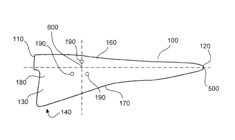
Figure 1 shows a diagrammatic plan view of a wind power installation
rotor blade according to a first embodiment. The wind power installation
rotor blade 100 has a rotor blade root 110, a rotor blade tip 120, a rotor
blade leading edge 160, a rotor blade trailing edge 170, a suction side 130,
a pressure side 140, a rotor blade outer casing 180 and openings 190 in
the suction side 130 and/or the pressure side 140. Optionally three
openings 190 can be provided.
The rotor blade 100 has a rotor blade longitudinal direction 500. The
three openings 190 can preferably be provided in or around the region of
the centre of gravity 600. In that way the rotor blade can be fitted in a
horizontally oriented position. The surface area on which the wind can act
can thus be reduced.
Figure 2 shows a diagrammatic sectional view of the wind power
installation rotor blade according to the first embodiment. The rotor blade
100 has a rotor blade root 110, a rotor blade tip 120, a suction side 130, a
pressure side 140, a rotor blade leading edge 160 and for example three
openings 190 in the outer casing 180 on the suction side or pressure side
which are provided in or around the region of the centre of gravity 600. In
addition thereto there can also be three openings on the pressure side or
the suction side. For example three fixing units 300 are provided between
the suction side 130 and the pressure side 140. Handling means for
example in the form of slings 200 can be introduced through the openings
190 into the interior of the rotor blade and fixed by means of the fixing
units 300.
. CA 02835230 2013-11-05
At their free ends the handling means 200 have an eye 210 which
can be fitted over a crane hook 700 (see Figure 3) so that the rotor blade
can be fitted in position or removed.
Figure 4 shows a diagrammatic sectional view of a rotor blade
5 according to the state of the art. The rotor blade has a rotor blade root
110 and a rotor blade tip 120. The handling means for example in the form
of slings 200 can be slung around the rotor blade and then fixed to the
crane hook 700.
From the comparison between the rotor blades in Figure 3 and Figure
4, it can be seen immediately that the rotor blade according to the
invention can have handling means in the form of slings 200 which are
substantially shorter than in the case of the rotor blade in accordance with
the state of the art in Figure 4. That also has the consequence that the
crane required for fitting or removing the rotor blade can be smaller.
According to the invention the end to be fixed of the handling means
or slings 200 is fixed on the side of the rotor blade, that is opposite to the
openings 190. That is particularly advantageous in regard to better
distribution of load when fitting and removing the rotor blade.
Figure 5 shows a plan view of a wind power installation rotor blade
according to a second embodiment. In particular the plan view in Figure 5
shows a view onto the rotor blade root region of the rotor blade. The rotor
blade has a rotor blade root 110, a rotor blade tip 120, a rotor blade
leading edge 160, a rotor blade trailing edge 170, a suction side 130, a
pressure side 140 and an outer casing 180. The rotor blade is at least
partially hollow in its interior 150 so that fixing units 300 can be fixed to
the outer casing 180 between the suction side 130 and the pressure side
140. In addition provided on the pressure side 140 are three openings 190
through which the slings 200 can be introduced into the interior 150 of the
rotor blade. The slings are then fixed to a fixing unit 300 by means of a
bolt 400.
The fixing unit 300 has two reinforcing plates 310 at its two ends.
The fixing unit is fixed to the outer casing 180 by means of the reinforcing
. CA 02835230 2013-11-05
=
6
plates 310. The fixing units 300 have a first and a second opening 320,
340. In the case shown in Figure 5 a bolt is introduced into the first hole
320 to releasably fix the slings 200. That provides that the distribution of
load or force is applied to or provided in the downwardly facing side (the
suction side 130 in Figure 5).
In its central region the fixing unit 300 has a recess portion 330.
Figure 6 shows a perspective view of the fixing unit for a rotor blade
according to the second embodiment. The fixing unit has two reinforcing
plates 310, a first and a second opening 320, 340 and in the central region
a recess portion 330. The sling 200 has a first eye 210 for receiving a
crane hook and a second eye 220 which serves for fixing to the fixing unit.
That is effected by introducing the bolt 400 into the first opening 320.
A recess portion is provided in the central region of the fixing unit
between the first and second opening.
Figure 7 shows a further perspective view of the fixing units 300 and
the slings 200 of a wind power installation rotor blade according to the
second embodiment. The fixing units each have two reinforcing plates 310,
a first and a second hole 340 and a recess portion 330 in the central
region. The slings 200 are introduced through a hole in the reinforcing
plate 310 and fixed by means of a bolt 400 to or in the first hole 320.
Figure 8 shows a perspective view of a fixing unit for a rotor blade
according to the second embodiment. The fixing unit 300 is for example of
a U-shaped configuration in cross-section and thus has two first holes 320,
two second holes 340 and two recess portions 330 in the central region
between the first and second holes. A bolt 400 can be passed through the
two first holes 320. That can serve for fixing the second eye of the sling
200.
Figure 9 shows a perspective view of a reinforcing plate of a fixing
unit for a rotor blade according to the second embodiment. In its centre
the fixing plate has a through hole 311 for receiving the handling means,
for example in the form of slings. The reinforcing plate further has a first
side 315 and a second side 316. The reinforcing plate also has three ends
- . CA 02835230 2013-11-05
7
312, 313, 314. The reinforcing plate 310 is bonded into or to the outer
casing for example in production of the rotor blade.
In the second embodiment the sling 200 is fixed in or to the first
opening 320 by means of a bolt 400. That is particularly advantageous
because that permits a better flow of forces. In that respect the second
opening 320 represents the opening which faces downwardly and is
opposite to the opening 190. The recess portion 330 serves for weight
reduction. In addition that makes it possible to prevent an air flow through
the interior 150 of the rotor blade being hindered. That air flow can be
used for example for heating the rotor blade. In addition the recess portion
can provide that a fitter can for example creep into the interior of the rotor
blade for fitting or removal purposes.
Preferably the interior of the rotor blade in the region of the holes
190 is so large that a man can creep therethrough to release the bolts 400
after fitment of the rotor blade has been effected. In addition that region is
so great that a man can creep therethrough to be able to inspect the
interior of the rotor blade.
Optionally the fixing unit 300 is made from a non-metallic material
like for example GRP or CRP. Only the bolt 400 can be made from metal.
The handling means or slings according to the invention are
preferably made from glass fibre and are soft so that they do not damage
the rotor blade. A flexible elastic sleeve can be provided in the region of
the opening 190 so that the slings do not damage the outer skin of the
rotor blade in the region of the opening 190. After fitment of the rotor
blade and after removal of the handling means the opening 190 can
optionally be sealed off from the interior by means of a plug. Optionally a
seal can be provided around the plug.
In an aspect of the invention a for example multi-part funnel which
can be fitted from the inside outwardly can be provided in the region of the
opening 190. Then the slings are introduced through the opening 190 and
fixed to the fixing unit 300. After rotor blade fitment the multi-part funnel
can then be removed from the interior.
CA 02835230 2013-11-05
,
8
In an aspect of the invention for example three openings 190 are
arranged around the centre of gravity 600 of the rotor blade. Provided
under the holes 190 are three fixing units between the suction side 130 and
the pressure side 140.
When fitting the rotor blade the first rotor blade is fitted by means of
a first crane for example in a 3 o'clock position. For that purpose the three
eyes 210 of the slings are suspended on a crane hook 700 so that the crane
holds the rotor blade in the 3 o'clock position for fitting it. After fitting
has
been effected the rotor blade is lowered. In that case it can happen that
only one of the slings is stressed while the other two slings are not. The
result of this can be that the opening 190 and the fixing unit 300 to which
the sling is fixed must carry the entire flow of forces for the rotor blade.
Accordingly the openings 190 and the reinforcing plates 310 must be of a
suitable design configuration.
When fitting the rotor blade it is advantageous for the slings 200 to
be removed only after fitment of the second rotor blade has been effected.
For that purpose the rotor blade is rotated to such an extent that the next
rotor blade can be fitted for example in the 9 o'clock position by means of a
second crane. That makes it possible to ensure that the rotor blade does
not move uncontrolledly downwardly when it rotates, and overshoots its
position.
In an aspect of the invention, instead of two slings, it is possible to
use a continuous sling of which one end is fixed to a first fixing unit and
the
second end is fixed to a second fixing unit.
In a further aspect of the invention belts for carrying the respective
forces are provided along the longitudinal direction of the rotor blade.
Reinforcing plates 310 are preferably connected to those belts to permit a
good flow of forces.
The reinforcing plates have three ends 312, 313, 314 which are at an
angle of 60 relative to each other. That is particularly advantageous in
regard to the flow of forces.