Note: Descriptions are shown in the official language in which they were submitted.
CA 02835278 2013-11-06
WO 2012/154767
PCT/US2012/036988
CATHETER PLACEMENT DETECTION SYSTEM AND
METHOD FOR SURGICAL PROCEDURES
FIELD OF THE INVENTION
[0001] This
invention relates to methods and systems usable in human and animal
surgical procedures. For
example, the invention is applicable in the field of human
brachytherapy treatment procedures.
BACKGROUND OF THE INVENTION
[0002] In
typical brachytherapy surgical procedures, a physician inserts a number of
hollow catheters into a target structure within the human body. The number and
location of
the catheters is determined by a treatment plan, prescribed by a physician
based on imaging
studies usually done prior to treatment and many other factors. Often, a grid-
like guide
template structure is used as a guide for catheter insertion having insertion
passages
arranged in an orthogonal grid pattern. After inserting a number of such
catheters at the
prescribed loading position and depth, radioisotope sources are either placed
permanently in
the tissue as "seeds" (low dose rate or LDR brachytherapy), or are loaded into
the catheters
and are moved robotically inside the catheter to expose tissue surrounding the
catheter to a
desired radiation dose and then removed (high dose rate "HDR" brachytherapy).
The
radiation exposure dose is intended to cause radiotoxicity and destroy
targeted human
tissue, for example cancerous tumors or other structures. One application of
this technique
is in the area of human prostate brachytherapy. Among other applications,
these techniques
are also useful for human esophageal brachytherapy.
[0003] In human
prostrate brachytherapy, many catheters are placed at desired
positions using a locating template, positioned on the patient's perineum.
However, due to
structural characteristics of the catheters, their tips, and density
variations in the human
tissue, the insertion paths and final positions of the catheters cannot be
assumed to be along
straight lines extending from the template. Since the actual position of the
catheters is
critical to provide desired dose application, the radiologist needs
confirmation of the catheter
placements. This is presently done through ultrasonic imaging procedures.
Unfortunately,
the ultrasonic procedure used for human prostrate brachytherapy does not
provide a clear
image of catheter placement. There are numerous artifacts in the image
reconstruction and,
moreover, there are fundamental limits in the use of a rectally inserted
ultrasonic probe
during catheter placement procedures. For a real-time ultrasound guided HDR
prostate
implant procedure, catheter reconstruction has always been challenging and
time
consuming. This is due in part to many factors including high speckle noise,
inter-needle
interference, artifacts from calcifications, hyper-echoic tissues, and coil
markers for external
1
CA 02835278 2013-11-06
WO 2012/154767
PCT/US2012/036988
beam treatment. Furthermore, the catheters are always not straight. They are
often curved
either inadvertently, or intentionally to reduce normal tissue dose and
increase conformity,
making the reconstruction of catheter geometry even more difficult.
[0004] In view
of the foregoing, there is a need for a detection system which provides
higher accuracy and a reduction in evaluation time for verifying catheter
placement for
procedures such as LDR or HDR brachytherapy.
[0005] This
invention describes a novel system to perform real-time catheter tracking.
This system will significantly improve catheter reconstruction speed and
accuracy while
increasing operator confidence in precise dose delivery.
BRIEF DESCRIPTION OF THE DRAWINGS
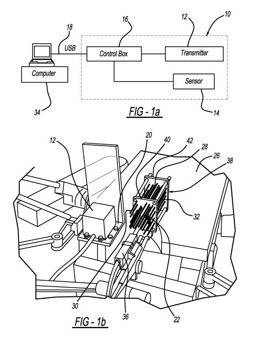
[0006] Fig.
1(a) is a schematic diagram of an electromagnetic tracking system in
accordance with one embodiment of the present invention.
[0007] Fig.
1(b) is a pictorial view of an electromagnetic tracking system in accordance
with one embodiment of the present invention.
[0008] Fig. 2
is a screenshot of a graphical user interface (GUI) in accordance with an
embodiment of the present invention.
[0009] Figs.
3(a)-3(f) are graphical views of catheter tracking results produced by an
embodiment of the present invention before calibration; Figs. 3(a), 3(c), and
3(e), and after
calibration; Figs. 3(b), 3(d), and 3(f). Figs. 3(a) and 3(b) are x-y plots,
Figs. 3(c) and 3(d) are
x-z plots, and Figs. 3(e) and 3(f) are y-z plots.
[0010] Fig.
4(a) is a graphical view of tracking results of catheter placement produced by
an embodiment of the present invention.
[0011] Fig 4(b)
is a graphical view of tracking results of catheter placement produced
using CT-based catheter reconstruction.
DETAILED DESCRIPTION OF THE INVENTION
[0012] In
accordance with this invention, an electromagnetic tracking system 10 is
employed. The tracking system 10 as shown in Fig. 1(a) utilizes a transmitter
unit 12,
preferably one using so-called passive magnetic DC technology (e.g. products
available
from Ascension Technology Corporation including their "3D Guidance driveBAY",
or "3D
Guidance trakSTAR" systems). It is
also possible to other tracking systems 10 in
accordance with this invention, including those using passive magnetic AC
technology.
Tracking system 10 include the transmitter 12 mentioned previously, along with
one or more
miniature sensors 14 which are small enough in size to be inserted into
brachytherapy
catheters 22 (catheters 22 may also be referred to as "needles"), shown in
Figure 1(b). The
2
CA 02835278 2013-11-06
WO 2012/154767
PCT/US2012/036988
system 10 allows the relative position between the transmitter 12 and sensor
14 to be
detected and displayed. Catheters 22 have a distal end 28, proximal end 30,
and a hollow
lumen 32 therebetween.
[0013] Systems
utilizing passive magnetic DC (or AC) technology like system 10 are
inherently influenced by surrounding structures of magnetic materials. In the
particular
applications considered here, a patient on a surgical couch or operating table
26 during a
brachytherapy catheter placement procedure has numerous metallic structures
near the
surgical site, including the table, surgical tools, and the brachytherapy
catheter placement
system. These metallic structures are sources of interference. It is therefore
necessary in
accordance with this invention to correct measured position values using the
aforementioned
passive magnetic DC (or AC) technology systems to actual positions. For other
electromagnetic systems for example using radio frequency or other location
systems, it is
expected that structures of the surgical site will also be sources of
measurement interference
requiring correction, thereby also requiring correction.
[0014] Both the
transmitter 12 and the sensor 14 are connected to control box 16
controlled by a computer 34 through USB cable 18. An exemplary transmitter 12
has a range
of 36 cm and is placed on a supporting bracket 20, as shown in Figure 1(b),
that can be
positioned close to the surgical site and the catheters 22. An exemplary
sensor 14 has a
diameter of 0.9 mm and can be inserted into 16-gauge needles or catheter
lumens 32.
Figure 1(b) further shows an ultrasonic probe attached to a stepper unit to
move forward and
backward for imaging the prostate as part of HDR brachytherapy treatment. That
figure
further shows a three-dimensional grid like phantom structure 38 used to
demonstrate the
present invention, and provide system calibration. Structure 38 has grid
plates 40 and 42
having apertures for receiving catheters 22 and positioning them in desired
orientations.
[0015] Figure 2
shows the graphical user interface (GUI) image 24 of the program used
to control the system 10. The tracking process in accordance with this
invention is conducted
in the following steps: 1) after finishing insertion of a plurality of
catheters 22 into the patient
at the surgical site, sensor 14 is inserted into the proximal end 30 of one
catheter 22, and
driven to the distal end 28; 2) click the "Start Tracking" button on the GUI
and then retract
the sensor 14 out of the catheter 22; 3) once the sensor 14 is out of the
catheter 22, click the
"Stop Tracking" button on the GUI. During the above process, transmitter 12
and sensor 14
are activated to provide tracking. The tracking data corresponds to the
catheter 22 will be
saved to the plan; 4) go to the next catheter 22 and repeat the previous steps
for all
catheters; 5) apply calibration (described below) to the tracking result (the
calibration can
also be applied during the tracking process); 6) export the tracking results
(RT plan) to the
treatment planning system for planning. Since the sensor 14 is physically
constrained to
3
CA 02835278 2013-11-06
WO 2012/154767
PCT/US2012/036988
move along the catheter lumen 32, detecting its path also describes the shape
and position
of the inserted catheters 22. Calibration could also be conducted during
insertion of sensor
14, i.e. "Start Tracking" could be done during sensor 14 insertion rather than
during
retraction as mentioned above. Moreover, tracking could be done in both
directions if
desired.
[0016]
Calibration is accomplished using a calibration algorithm involving a
scattered
data interpolation scheme. The QA phantom structure 38 with known catheter
positions
(shown in Figure 1(b)) is used for calculating calibration profiles. Figures
3(a)-3(f) shows
orthogonal views of the tracking results for the 10 catheters 22 displayed in
the right panel of
Figure 2 using phantom 38. The reconstruction results before correction
(Figures 3(a), 3(c),
and 3(e)) and after correction (Figures 3(b), 3(d), and 3(f)) are shown. As
shown in Figures
3(a), 3(c), and 3(e), the system's accuracy degrades as the sensor-transmitter
distance
increases. In one experiment using the present invention tracking at distances
of 140mm to
280mm was conducted. However, after calibration, the error can be minimized as
shown in
Figures 3(b), 3(d), and 3(f). Once the actual positions of the catheters 22
are known,
treatment plan modification can be made to provide desired dosing. Once the
calibration
factors for a particular surgical arrangement are developed using the phantom
structure 38,
the assumption is made that patient-to-patient differences are small as
related to the
calibration. The calibration factors determined as described above are used to
modify
detected positions of catheters positioned in a patient to more closely
determine actual
catheter placement.
[0017] As
mentioned previously, calibration is needed due to the influences of
surrounding magnetic structures and other sources of interference. Even
without such
interference however, calibration will be needed since outputs are affected by
the position of
transmitter 12 relative to catheters 22. Accordingly, it is necessary that the
relationship
between the position of transmitter 12 and the catheters 22 is reproduced
between
establishing the correction process using the phantom structure 38 and during
surgical
procedures.
[0018] As a
reproducibility study for the present invention, the calibration profiles were
tested under various equipment arrangements. While the profiles are sensitive
to the relative
position between the transmitter 12 and the operating table 26, reasonable
position
variations of the stepper, ultrasound machine, and leg stirrups (sources of
transmitter-sensor
tracking errors) introduce < 1 mm error.
[0019] To
further validate the system 10, straight catheters 22 in the QA phantom
structure 38 were bended and tracked with the system as shown in Figure 4(a).
To verify the
corrected catheter positions, the phantom 38 was then scanned with CT
(computed
4
CA 02835278 2013-11-06
WO 2012/154767
PCT/US2012/036988
tomography) and the catheters 22 were reconstructed in the Oncentra0 Brachy,
as shown in
Figure 4(b). The CT scanned positions are used as a baseline of actual
catheter positions. It
should be noted that CT scanning of catheter placements is not preferred for
patient use due
to cost, complexity, and patient radiation dose exposure, but is used here to
validate the
inventive approach. In an experiment for demonstrating the present invention,
average
tracking accuracies after calibration were found to be 0.4 0.3 mm; and 2.4
1.7 mm
without calibration. The max standard deviation was 0.9 mm in the test range
for the
reproducibility test. Thus, the calibration steps used in this invention
significantly improved
catheter position determination. The total tracking time for ten catheters 22
was less than
four minutes and the reconstruction result matches CT data within 2.0 mm.
[0020] Compared
to conventional ultrasound based real-time catheter reconstruction
method in the HDR prostate implant; the system 10 of this invention can reduce
the error
from > 3 mm to < 1.5 mm, and shorten the procedure time from 15-60 minutes to
< 4
minutes. Furthermore, this technique can also be used for other HDR implants.
[0021] While
the present invention has been described in terms of certain preferred
embodiments, it will be understood that the invention is not limited to the
disclosed
embodiments, as those having skill in the art may make various modifications
without
departing from the scope of the following claims.