Note: Descriptions are shown in the official language in which they were submitted.
CA 02835485 2013-11-07
WO 2012/154862 PCT/US2012/037138
Title:
[001] IMPLANTABLE MEDICAL DEVICE HAVING ENHANCED ENDOTHELIAL
MIGRATION FEATURES AND METHODS OF MAKING THE SAME
Background of the Invention
[002] The present invention relates generally to implantable medical devices
and more
particularly to controlling surface properties of implantable biocompatible
materials suitable for
fabrication of implantable medical devices.
[003] Implantable medical devices are fabricated of materials that are sub-
optimal in terms of
the biological response they elicit in vivo. Many conventional materials used
to fabricate
implantable devices, such as titanium, polytetrafluoroethylene, silicone,
carbon fiber and
polyester, are used because of their strength and physiologically inert
characteristics. However,
tissue integration onto these materials is typically slow and inadequate.
Certain materials, such as
silicone and polyester, elicit a significant inflammatory, foreign body
response that drives fibrous
encapsulation of the synthetic material. The fibrous encapsulation may have
significant adverse
effects on the implant. Moreover, conventional biomaterials have proved
inadequate in eliciting a
sufficient healing response necessary for complete device integration into the
body. For example,
in devices that contact blood, such as stents and vascular grafts, attempts to
modify such devices
to promote endothelial cell adhesion may have a concomitant effect of making
the devices more
thrombogenic. There still remains a need for a medical device that stimulates
endothelial
proliferation and movement when implanted in order to form an endothelial
layer over the
medical device. Furthermore, there is a remaining need for a method of
fabricating such a
medical device.
Summary of the Invention
[004] In one embodiment, an implantable medical device having enhanced
endothelial
migration features, comprises: a structural member including a cross-section
having a leading
edge and a trailing edge interconnected by a third surface region, the leading
edge including a
second surface region in a generally curvilinear cross-section, and the
trailing edge including a
fourth surface region in a generally curvilinear cross-section, whereby fluid
flow over the second
surface region generate shear stress at the second surface region without an
eddy region in the
second surface region. In another embodiment, the implantable biocompatible
material includes
a plurality of geometrically functional features. In one embodiment, the
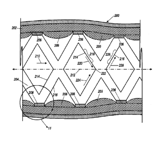
implantable
1
CA 02835485 2013-11-07
WO 2012/154862 PCT/US2012/037138
biocompatible material includes a plurality of grooves disposed on at least
one of the trailing
edge, leading edge, and surface regions of the structural member.
[0051 In a further embodiment, a method of forming an implantable medical
device having
enhanced endothelial migration features, comprises: forming a structural
member including a
.. leading edge and a trailing edge interconnected by a third surface region,
the leading edge
including a second surface region in a generally curvilinear cross-section,
and the trailing edge
including a fourth surface region in a generally curvilinear cross-section,
whereby fluid flow
over the second surface region generate shear stress at the second surface
region without an eddy
region in the second surface region.
Brief Description of the Figures
[006] FIG. 1 is a perspective view of an embodiment of including evenly
distributed elevated
geometric physiologically functional features on the surface of an implantable
material.
[007] FIG. 2 is cross-sectional view of FIG. 1 along line 2 ¨2.
[008] FIG. 3 is a perspective view of an embodiment including evenly
distributed chemically
defined geometric physiologically functional features on the surface of an
implantable material.
[009] FIG. 4 is a cross-sectional view of FIG. 3 along line 4 ¨ 4.
[010] FIGS. 5A-5D are cross-sectional diagrammatic views of an embodiment, the
combination of a-d representing the steps to make an inventive implantable
material with
elevated geometric physiologically functional features.
[011] FIGS. 6A-6D are cross-sectional diagrammatic views of an embodiment, the
combination of a-d representing the steps to make an inventive implantable
material with
chemically defined geometric physiologically functional features.
[012] FIGS. 7A-7B are cross-sectional diagrammatic views of one embodiment;
FIG. 7C is a
top view of one embodiment; and FIGS. 7D-7E are cross-sectional diagrammatic
views of one
.. embodiment of making the implantable material.
[013] FIGS. 8A-8D are cross-sectional diagrammatic views of one embodiment.
[014] FIGS. 9A-9B are cross-sectional diagrammatic views of one embodiment.
[015] FIG. 10 is a cross-sectional view of an artery having an arterial wall
including an
implantable medical device
[016] FIG. 11 is an enlarged cross-sectional view from circled 11 in FIG. 10
of the implantable
medical device, in accordance with one embodiment.
2
CA 02835485 2013-11-07
WO 2012/154862 PCT/US2012/037138
[017] FIG. 12A is a cross-sectional view of one embodiment of the structural
member having a
generally rounded rectangular cross-section; FIG. 12B is a cross-sectional
view of one
embodiment of the structural member having a generally hexagonal cross-
section; and FIGS.
12C-12D are cross-sectional views of one embodiment of the structural member
entirely lacking
an eddy region.
[018] FIG. 13A is a cross-sectional view of one embodiment of the trailing
edge of a structural
member having a generally rounded rectangular cross-section; and FIGS. 13B-13C
are cross-
sectional views of one embodiment of the trailing edge of the structural
member 206 having a
modified cross-section.
[019] FIG. 14A is a perspective view of one embodiment of the structural
member including a
luminal surface, a leading edge, and a trailing edge; FIG. 14B is a
perspective view of one
embodiment of the structural member including a luminal surface, the leading
edge, and the
trailing edge including grooves disposed therein or thereon
[020] FIG. 15 is a perspective view of one embodiment of the structural member
including a
main highway of the grooves.
[021] FIGS. 16A-16B are photographs of human aortic EC migration onto 1 x 1-
cm, 316L
stainless steel flat coupons after fixation and Giemsa staining, where entire
sheet then was placed
into parallel plate flow chamber and exposed to fluid-imposed arterial level
shear (15
dynes/cm2), as shown in FIG. 16A, and low shear (1.5 dynes/cm2), as shown in
FIG. 16B, wall
stress on right for 4 days, and the arrow indicates that direction of flow.
[022] FIG. 17 is a graph showing the percentage of total area of surface
obstacles covered by
ECs after 4 days with flow at 16 dynes/cm2; where ECs were grown to confluence
on polyester
film sheet with attached pieces of polyester film of increasing thickness
serving as obstacles; and
Asterisks indicate statistically significant difference compared with 25 nm.
[023] FIG. 18 is a photograph of human aortic ECs migrating on stainless steel
in direction of
arrow stained with Giemsa and 200X magnification; confluent human aortic ECs
were allowed
to migrate from firm collagen gel onto implanted 1 x 1-cm flat stainless steel
coupons with static
culture conditions for 7 days; on encounter with surface scratch, cells
deviate to follow feature;
and three cells in middle of field are aligned on single scratch.
[024] FIG. 19 is a photograph of human aortic ECs migrating on uniformly
scratched stainless
steel surface and stained with Giemsa stain at 200X magnification; cells
migrated from confluent
3
CA 02835485 2013-11-07
WO 2012/154862 PCT/US2012/037138
human aortic EC covered gel onto flat stainless steel coupons as described
previously; and
parallel scratch pattern was created with 320-grain carbide sand paper.
[0251 FIG. 20 is a graph showing Bars indicate mean number of ECs per mm2 on
stainless steel
microfabricated surfaces, with square section grooves from 7 to 20 ium wide;
grooves of defined
width were created with photolithographic process; grooved stainless steel lxl-
cm coupons were
implanted on endothelialized gel surface as described below, and cells were
allowed to migrate
onto surface for 7 days with static culture conditions; control indicates flat
surface; and surface
with 15- m grooves has significantly larger cell population.
Detailed Description of the Preferred Embodiments
[0261 In accordance with the embodiments disclosed herein, the capacity for
complete
endothelialization of conventional implantable materials, including metals and
polymers, may be
enhanced by imparting a pattern of chemically and/or physiochemically active
geometric
physiologically functional features onto a blood contacting surface of the
implantable material.
The inventive implantable devices may be fabricated of polymers, pre-existing
conventional
wrought metallic materials, such as stainless steel or nitinol hypotubes, or
may be fabricated by
thin film vacuum deposition techniques. The inventive implantable devices may
be intravascular
stent, stent-grafts, grafts, heart valves, venous valves, filters, occlusion
devices, catheters, osteal
implants, implantable contraceptives, implantable antitumor pellets or rods,
shunts and patches,
or other implantable medical devices having any construction or made of any
material as will be
hereinafter described. A medical device is an instrument, apparatus, implant,
in vitro reagent, or
other similar or related article, which is intended for use in the diagnosis
of disease or other
conditions, or in the cure, mitigation, treatment, or prevention of disease,
or intended to affect the
structure or any function of the body and which does not achieve any of it's
primary intended
purposes through chemical action within or on the body. Similarly, the
improvement of the
embodiments for the methods for manufacturing intravascular stents is also
believed to be
applicable to the manufacturing of any type of intravascular medical device,
stent-grafts, grafts,
heart valves, venous valves, filters, occlusion devices, catheters, steal
implants, implantable
contraceptives, implantable antitumor pellets or rods, shunts and patches,
pacemakers, medical
wires or medical tubes for any type of medical device, or other implantable
medical devices, as
will also be hereinafter described. A pacemaker (or artificial pacemaker, so
as not to be confused
with the heart's natural pacemaker) is a medical device that uses electrical
impulses, delivered by
4
CA 02835485 2013-11-07
WO 2012/154862 PCT/US2012/037138
electrodes contacting the heart muscles, to regulate the beating of the heart.
The electrodes may
be covered by tubing or other material that includes a surface that may
require endothelialization
and grooves thereon.
[027] In accordance with one embodiment, the inventive implantable materials
may be vacuum
.. deposited and resulting devices by vacuum deposition of either or both of
the base implant
material and the chemically and/or physiochemically active geometric
physiologically functional
features. Vacuum deposition permits greater control over many material
characteristics and
properties of the resulting material and formed device. For example, vacuum
deposition permits
control over grain size, grain phase, grain material composition, bulk
material composition,
surface topography, mechanical properties, such as transition temperatures in
the case of a shape
memory alloy. Moreover, vacuum deposition processes will permit creation of
devices with
greater material purity without the introduction of large quantities of
contaminants that adversely
affect the material and, therefore, the mechanical and/or biological
properties of the implanted
device. Vacuum deposition techniques also lend themselves to fabrication of
more complex
devices than those that are manufactured by conventional cold-working
techniques. For example,
multi-layer structures, complex geometrical configurations, extremely fine
control over material
tolerances, such as thickness or surface uniformity, are all advantages of
vacuum deposition
processing.
[0281 In vacuum deposition technologies, materials are formed directly in the
desired geometry,
e.g., planar, tubular, etc. The common principle of vacuum deposition
processes is to take a
material in a minimally processed form, such as pellets or thick foils, known
as the source
material and atomize them. Atomization may be carried out using heat, as is
the case in physical
vapor deposition, or using the effect of collisional processes, as in the case
of sputter deposition,
for example. In some forms of deposition a process such as laser ablation,
which creates
microparticles that typically consist of one or more atoms, may replace
atomization; the number
of atoms per particle may be in the thousands or more. The atoms or particles
of the source
material are then deposited on a substrate or mandrel to directly form the
desired object. In other
deposition methodologies, chemical reactions between ambient gas introduced
into the vacuum
chamber, i.e., the gas source, and the deposited atoms and/or particles are
part of the deposition
process. The deposited material includes compound species that are formed due
to the reaction of
the solid source and the gas source, such as in the case of chemical vapor
deposition. In most
5
CA 02835485 2013-11-07
WO 2012/154862 PCT/US2012/037138
cases, the deposited material is then either partially or completely removed
from the substrate, to
form the desired product.
[029] Vacuum deposition of the metallic and/or pseudometallic films permits
tight process
control and films may be deposited with a regular, homogeneous atomic and
molecular pattern of
distribution along their fluid-contacting surfaces. This avoids the marked
variations in surface
composition, creating predictable oxidation and organic adsorption patterns
and has predictable
interactions with water, electrolytes, proteins and cells. In particular, EC
migration is supported
by a homogeneous distribution of binding domains that serve as natural or
implanted cell
attachment sites in order to promote unimpeded migration and attachment.
[030] Secondly, in addition to materials and devices that are made of a single
metal or metal
alloy layer, the inventive grafts may be comprised of a layer of biocompatible
material or of a
plurality of layers of biocompatible materials formed upon one another into a
self-supporting
multilayer structure because multilayer structures are generally known to
increase the
mechanical strength of sheet materials, or to provide special qualities by
including layers that
have special properties such as superelasticity, shape memory, radio-opacity,
corrosion
resistance etc. A special advantage of vacuum deposition technologies is that
it is possible to
deposit layered materials and thus films possessing exceptional qualities may
be produced (cf.,
H. Holleck, V. Schier: Multilayer PVD coatings for wear protection, Surface
and Coatings
Technology, Vol. 76-77 (1995) pp. 328-336). Layered materials, such as
superstructures or
multilayers, are commonly deposited to take advantage of some chemical,
electronic, or optical
property of the material as a coating; a common example is an antireflective
coating on an
optical lens. Multilayers are also used in the field of thin film fabrication
to increase the
mechanical properties of the thin film, specifically hardness and toughness.
[031] Thirdly, the design possibilities for possible configurations and
applications of the
inventive graft are greatly realized by employing vacuum deposition
technologies. Specifically,
vacuum deposition is an additive technique that lends itself toward
fabrication of substantially
uniformly thin materials with potentially complex three dimensional geometries
and structures
that cannot be cost-effectively achieved, or in some cases achieved at all, by
employing
conventional wrought fabrication techniques. Conventional wrought metal
fabrication techniques
may entail smelting, hot working, cold working, heat treatment, high
temperature annealing,
precipitation annealing, grinding, ablation, wet etching, dry etching, cutting
and welding. All of
6
CA 02835485 2013-11-07
WO 2012/154862 PCT/US2012/037138
these processing steps have disadvantages including contamination, material
property
degradation, ultimate achievable configurations, dimensions and tolerances,
biocompatibility and
cost. For example conventional wrought processes are not suitable for
fabricating tubes having
diameters greater than about 20 mm, nor are such processes suitable for
fabricating materials
having wall thicknesses down to about 1 1..tm with sub-11m tolerances.
[032] The embodiments disclosed herein takes advantage of the discovered
relationship
between chemically or physiochemically-active geometric physiologically
functional features
defined and distributed on a blood contact surface and enhanced endothelial
cell binding,
proliferation and migration over the blood contact surface of the implantable
material. The
embodiments disclosed herein involve focal adhesion point formation during
cellular movement
and the well-established observation known as anchorage dependence, that
spreading cells
proliferate faster than non-spreading cells. The addition of a patterned array
of geometric
physiologically functional features having a hydrophobic, hydrophilic or
surface energy
difference relative to the surface onto which the geometric physiologically
functional features are
added, enhances the binding, proliferation and migration of endothelial cells
to and between the
geometric physiologically functional features and across the surface.
[033] The geometric physiologically functional features disclosed herein may
be formed on, in,
or through one or more layers of vacuum deposited biocompatible material. In a
first
embodiment, the one or more layers of vacuum deposited biocompatible material
are deposited
on a layer of bulk material. In a second embodiment, a plurality of layers of
vacuum deposited
biocompatible material is deposited on one another to form a self-supporting
multilayer
structure. Each of the first and second embodiments includes several aspects.
In a first aspect, the
geometric physiologically functional features may have a non-zero thickness
corresponding to a
thickness of one or more layers of the vacuum deposited material.
Alternatively, in other aspects,
the geometric physiologically functional features may have a zero thickness or
a thickness
greater than one or more layers of the vacuum deposited material.
[034] Below about 3 pm in thickness, the interactions between endothelial
cells and the
geometric physiologically functional features are primarily chemical and
electrochemical.
Geometric physiologically functional features having thicknesses greater than
3 ?Am and up to
about 20 [tm may also be employed, it being understood that as the thickness
of the geometric
physiologically functional feature increases there is a decreasing chemical
and/or
7
CA 02835485 2013-11-07
WO 2012/154862 PCT/US2012/037138
electrochemical interaction between the geometric physiologically functional
feature and the
endothelial cells and an increasing physical interaction (topographic guidance
effect).
[0351 Additionally, it has been found that by employing UV irradiation to
oxidized titanium or
titanium-alloy surfaces, photochemical alteration of the surface titanium
oxides alter the
hydrophobicity of the exposed titanium oxides and act as affinity binding and
migration sites for
endothelial cell attachment and proliferation across a titanium or titanium-
alloy surface. Where
UV irradiation is employed, the thickness of the photochemically altered
regions of titanium
oxide are, for all practical purposes, 0 um. Thus, within the context of the
present application, the
term "geometric physiologically functional features" is intended to include
both physical
.. members and photochemically-altered regions having thicknesses having
thicknesses down to 0
um or between 0 and 1000 nm.
[036] In FIG. 1, a portion of an implantable material 10 showing the surface
material 12 with
described elevated geometric physiologically functional features 14 is
illustrated. The geometric
physiologically functional features are elevated from the surface of the
implantable material to a
height ranging from about 1 nm to about 20 [tm. Preferably, the height of the
geometric
physiologically functional feature 14 ranges from about 1 nm to about 3 um.
The shape of
geometric physiologically functional features can be either circular, square,
rectangle, triangle,
parallel lines, straight or curvilinear lines or any combination thereof. Each
of the geometric
physiologically functional features is preferably from about mm to about 75
um, and preferably
from about mm to 50 um in feature width 16, or feature diameter if the
geometric
physiologically functional feature is circular. A gap distance 18 between each
of the geometric
physiologically functional features may be less than, about equal to or
greater than the feature
width 16, i.e., between about 1 nm to about 75 um edge-to-edge.
[037] FIG. 2 is a cross-sectional view along line 2-2 in FIG. 1. One of the
elevated geometric
physiologically functional features 14 is shown on the surface 12 of the
implantable material.
[038] In FIG. 3, a layer of a titanium or titanium-alloy material 20 is
heating to oxidize and
form titanium dioxide on the surface of the material 20. In one embodiment,
the layer of titanium
or titanium-alloy material 20 is deposited over one or more layers of vacuum
deposited material
in a self-supporting multilayer structure. In another embodiment, the layer of
titanium or
titanium-alloy material 20 is deposited over a bulk material that may have one
or more layers of
vacuum deposited material deposited thereon.
8
CA 02835485 2013-11-07
WO 2012/154862 PCT/US2012/037138
[039] The geometric physiologically functional features 24 are formed by
exposing the layer of
material 20 to UV through a pattern mask. UV irradiation alters the titanium
oxides in the areas
of geometric physiologically functional features 24, thereby chemically
altering the geometric
physiologically functional features 24 relative to the surrounding the
surrounding surface area 22
of material layer of material 20. The shape of geometric physiologically
functional features can
be circular, square, rectangle, triangle, parallel lines, intersecting lines
or any combination. Each
of the geometric physiologically functional features is from about 1 nanometer
to about 75 [tm,
and preferably from about 1 nanometer to about 50 [tm in feature width 16, or
feature diameter if
the geometric physiologically functional feature is circular. The gap distance
28 between each
component of the geometric physiologically functional features may be less
than, about equal to
or greater than the feature width 26.
[040] FIG. 4 is a cross-sectional view of FIG. 3 along line 4-4. The described
geometric
physiologically functional features 24 are indicated by the dotted lines,
which indicate that the
geometric physiologically functional features 24 are at the same level of the
surrounding surface
22. Referring to FIG. 5A, a portion of an implantable material 46 with surface
42 and 44 is
shown. Referring to FIG. 5B, a machined mask 48 having laser-cut holes 40 of
defined size
ranging from about 1 nm to about 75 [tm, and preferably from about 1 nm to 50
[tm, patterned
throughout coats at least one surface 42 of the implantable material 46 and is
tightly adhered to
the covered surface 42. Referring to FIG. 5C, a thin film of material 14 was
deposited into the
space as defined by the holes 40, as seen in FIG. 5B, in the mask 48 by thin
film deposition
procedures. Referring to FIG. 5D, after deposition, the mask is removed to
reveal the geometric
physiologically functional features 49 patterned across the at least one
surface 42 of the
implantable material 46.
[041] As described above, the shape of the holes in the mask could be in any
of the shapes
described for the geometric physiologically functional features including:
circle, square,
rectangle, triangle, parallel lines and intersecting lines, or any combination
thereof. In the thin
film deposition embodiment of the manufacturing the geometric physiologically
functional
features, the geometric physiologically functional features are elevated from
the surface of the
implantable material. The thickness of the geometric physiologically
functional features is based
upon the thickness of the holes in the mask, the thickness ranging from about
1 nm to about 20
9
CA 02835485 2013-11-07
WO 2012/154862 PCT/US2012/037138
micrometers. Preferably, the thickness of the holes in the mask range from
about 1 nm to about 3
micrometers.
[042] The variations of geometric physiologically functional features may be
added to a surface
of an implantable biocompatible material by vacuum depositing a layer or
layers of
biocompatible material on the surface. In one embodiment, the geometry of the
layer or layers of
deposited material defines the geometric physiologically functional features.
For example, an
implantable material 100 has a surface 104, as illustrated in FIG. 7A. In one
embodiment, the
implantable biocompatible material may comprise one or more layers 102 of
vacuum deposited
material formed into a self-supporting structure, as illustrated by FIG. 7A
showing a first layer
102a, a second layer 102b, a third layer 102c, a fourth layer 102d, and a
fifth layer 102e. In
another embodiment, the implantable biocompatible material includes a bulk
material, either a
bulk material alone or a bulk material covered by the one or more layers 102a-
102e of vacuum
deposited biocompatible material. Five layers 102a-102e of vacuum deposited
material are
illustrated; however, any number of layers may be included as desired or
appropriate.
[043] The one or more layers 102, may have thicknesses that are the same or
different as
desired or appropriate. Each layer may have a thickness in a range from about
1 nanometer to
about 20 micrometers, from about 1 nanometer to about 10 micrometers, from
about 1 nanometer
to about 5 micrometers, or from about 1 nanometer to about 3 micrometers.
Alternating layers
102 of varying thicknesses may be applied as to accommodate the geometric
physiologically
functional features.
[044] In this embodiment, the geometric physiologically functional features
may be added to
the surface 104 by adding one or more layers 102 of vacuum deposited material.
For example,
referring to FIGS. 7B-7E, in one process, a mask 106 having holes 108 of
defined size disposed
therethrough and patterned throughout coats and is tightly adhered to at least
a first portion of the
.. surface 104. The holes 108 may be cut through the mask 106, for example, by
using a laser or
other method for forming holes through a material as known in the art, or the
mask 106 may be
fabricated including the holes 108 as may be known in the art. The thickness
of the holes 108
may range about 1 nanometer to about 20 micrometers, from about 1 nanometer to
about 10
micrometers, from about 1 nanometer to about 5 micrometers, or from about 1
nanometer to
about 3 micrometers.
1045] The shape of the holes 108 as seen in FIG. 7C or as looking in the
direction of arrow 110
may be any of the shapes described for the geometric physiologically
functional features
including: circle, square, rectangle, triangle, polygonal, hexagonal,
octagonal, elliptical, parallel
lines and intersecting lines, or any combination thereof. The holes 108 may
have a width 112, or
diameter 112 if the holes are circular, in a range between about 1 nanometer
and about 75
micrometers, between about 1 nanometer and about 50 micrometers, between about
1 nanometer
and about 2000 nanometers, or between about 1 nanometer and about 200
nanometers. Adjacent
holes 108 may be spaced apart by a distance D in a range from about 1
nanometer to about 20
micrometers, from about 1 nanometer to about 10 micrometers, from about 1
nanometer to about
5 micrometers, or from about 1 nanometer to about 3 micrometers. The distance
D may be less
than, about equal to or greater than the width 112. In another embodiment (not
shown), the width
112 of each of the holes 108 and/or the distance D between adjacent holes 108
may vary in size
to form a patterned array of the holes 108.
[046] Referring to FIG. 7D, a layer 114 of material was deposited into a space
as defined by
the holes 108 in the mask 106 by vacuum deposition. The layer 114 has a
thickness essentially
the same as that of the mask 106. In some embodiments, the thickness of the
mask may be
variable across the mask 106. After removal of the mask 106, geometric
physiologically
functional features 116 are revealed patterned across the surface 104 of the
implantable material
100. Each of the geometric physiologically functional features 116 includes a
top surface 118.
.. Each of the geometric physiologically functional features 116 has
dimensions as described
hereinabove for the holes 108 in the mask 106.
10471 In another embodiment where geometry of the layer or layers of deposited
material
defines the geometric physiologically functional features, a patterned array
of recesses may be
formed each having a hydrophobic, hydrophilic or surface energy difference
relative to the
surface into which the recesses are added, meaning a top most surface of the
deposited layers, the
difference enhancing the binding, proliferation and migration of endothelial
cells to and between
the recesses and across the surfaces, recessed and top most. The hydrophobic,
hydrophilic or
surface energy differences relative to the surface may be formed, by way of
example, any of the
methods disclosed in commonly assigned U.S. Patent Application No. 12/428,981,
filed April,
.. 23, 2009.
11
CA 2835485 2018-08-07
CA 02835485 2013-11-07
WO 2012/154862 PCT/US2012/037138
[048] In this embodiment, the recesses may be formed by a relative lack of
deposition of a layer
or layers onto a surface, or by machining recesses through a layer or layers
of material vacuum
deposited on a surface. For example, to produce a pattern of recesses similar
to the pattern of
geometric physiologically functional features 116 illustrated in FIG. 7E, in
one example, a
process begins by executing the steps described hereinabove with regard to
FIGS. 7A-7E, to
produce the pattern of geometric physiologically functional features 116
illustrated in FIG. 7E,
except in this embodiment, the layer 114 of material is a sacrificial layer of
material that is
removed in a subsequent step.
[049] Referring to FIGS. 8A and 8B, a layer 120 of material is deposited into
spaces between
the geometric physiologically functional features 116 by vacuum deposition.
The layer 120 has a
thickness essentially the same as that of the geometric physiologically
functional features 116. In
this embodiment, after vacuum deposition of the layer 120, the geometric
physiologically
functional features 116 of the sacrificial layer 114 are removed, for example,
by chemical
etching or other method known in the art to reveal geometric physiologically
functional features
122 patterned across the surface 104 of the implantable material 100. Each of
the geometric
physiologically functional features 122 is a recess that has a thickness or
depth between a surface
124 of the layer 120 and the surface 104.
[050] The shape of the recesses 122 as seen looking in the direction of arrow
126 in FIG. 8B
may be any of the shapes described for the geometric physiologically
functional features
including: circle, square, rectangle, triangle, polygonal, hexagonal,
octagonal, elliptical, parallel
lines and intersecting lines, or any combination thereof. The recesses 122 may
have the width
112, or diameter if the recesses 122 are circular, in a range between about 1
nanometer and about
75 micrometers, alternatively between about 1 nanometer and about 50
micrometers,
alternatively between about 1 nanometer and about 2000 nanometers, or
alternatively between
.. about 1 nanometer and about 200 nanometers. Adjacent recesses 122 may be
spaced apart by the
distance D in a range from about 1 nanometer to about 20 micrometers, from
about 1 nanometer
to about 10 micrometers, from about 1 nanometer to about 5 micrometers, or
from about 1
nanometer to about 3 micrometers. The distance D may be less than, about equal
to or greater
than the width 112. In another embodiment (not shown), the width 112 of each
of the recesses
.. 122 and/or the distance D between adjacent recesses 122 may vary in size to
form a patterned
array of the recesses 122.
12
CA 02835485 2013-11-07
WO 2012/154862 PCT/US2012/037138
[051] In another embodiment, the recesses 122 having width and spacing as
described
hereinabove with regard to FIGS. 8A and 8B may be formed by machining the
recesses 122
through a layer or layers 128 of vacuum deposited material. For example, an
implantable
material 130 having a surface 132, may comprise a bulk material 134, the one
or more layers 128
.. of vacuum deposited material, or the bulk material 134 and the one or more
layers 128 of
vacuum deposited material, as illustrated in FIG. 9A.
[052] Alternatively, as shown in FIG. 8C, the geometric physiologically
functional features
116 themselves include a plurality of deposited layers, wherein the geometric
physiologically
functional features 116 include the first layer 102a, the second layer 102b,
and the third layer
102c. The geometric physiologically functional features 116 are deposited
through a mask as
previously indicated, on top of structural material of the stent or other
medical device include
deposited layer 102d and 102e. Alternatively, the geometric physiologically
functional features
116 include the first layer 102a and the second layer 102b, deposited through
the mask whereby
the structural material of the stent or other medical device includes the
layers 102c-102d.
Alternatively, the geometric physiologically functional features 116 include
the first layer 102a,
the second layer 102b, the third layer 102c, and the fourth layer 102d,
whereby the structural
material of the stent or other medical device includes the fifth layer 102e.
When additional layers
102a-102d are included in the geometric physiologically functional feature
116, the thickness of
the layers as deposited can be modified to be a narrower or decreased
thickness as to allow for
the geometric physiologically functional feature 116 to be adjusted to a
particular thickness. The
layers of different vacuum deposited materials can be deposited to create the
elevated surfaces
having inherently different material properties. Alternatively, layers of the
same vacuum
deposited material can be deposited having differences in grain size, grain
phase, and/or surface
topography or variations of hydrophobic, hydrophilic or surface energy
difference relative to the
surface of the stent or structural material.
[053] Alternatively, as shown in FIG. 8D, the recesses 122 may include a
plurality of layers
102 to provide for differences in grain size, grain phase, and/or surface
topography or variations
of hydrophobic, hydrophilic or surface energy difference relative to the
surface of the stent or
structural material. The recesses 122 may be formed by the surface 124 being
deposited through
a mask as to form the layer 120 that gives rise to the plurality of recesses
122 with a wall 123. As
such, the recesses 122 include an inner wall 123 including the first layer
102a, the second layer
13
CA 02835485 2013-11-07
WO 2012/154862 PCT/US2012/037138
102b, and the third layer 102c, whereby the surface 104 is on layer 102d,
which is exposed on
the bottom of the recess 122 and surface 124 is on top of layer 102a.
Alternatively, the recesses
122 may include a wall of the first layer 102a and the second layer 102b,
whereby the surfaces
124 are deposited through a mask, and the structural material of the stent or
other medical device
includes the layers 102d-102e. Alternatively, the recesses 122 include a wall
of the first layer
102a, the second layer 102b, the third layer 102c, and the fourth layer 102d,
and surfaces 124 are
deposited through a mask whereby surface 102e that acts as the surface 104 of
the structural
material of the medical device. When additional layers 102a-102d are included
as the wall in the
geometric physiologically functional feature 116, the thickness of the layers
as deposited can be
modified to be a narrower or decreased thickness as to allow for the geometric
physiologically
functional feature 116 to be adjusted to a particular thickness. The layers of
different vacuum
deposited materials can be deposited to create recesses having inherently
different material
properties. Alternatively, layers of the same vacuum deposited material can be
deposited having
differences in grain size, grain phase, and/or surface topography or
variations of hydrophobic,
hydrophilic or surface energy difference relative to the surface of the stent
or structural material.
[054] Referring to FIG. 9B, recesses 136 may be machined into the surface 132
of the
implantable material 130 to have a depth greater than a thickness of a first
layer of material 128a
or recesses 138 may be machined into the surface 132 of the implantable
material 130 to have a
depth greater than a thickness of the first and second layers 128a, 128b of
material. Two layers
are illustrated for convenience of explanation and illustration; however, any
number of layers
128 of material may be used as desired or appropriate. In this aspect, each of
the recesses 136 has
a thickness or depth between the surface 132 of the layer 128a and a surface
140 that is within a
second layer 128b. Similarly, each of the recesses 138 has a thickness or
depth between the
surface 132 of the layer 128a and a surface 142 that is within the bulk
material 134.
[055] An implantable material including geometric physiologically functional
features
comprising a layer or layers of vacuum deposited material, as illustrated by
the geometric
physiologically functional features 116 in FIG. 7E, recesses disposed through
one or more layers
of vacuum deposited material, as illustrated by the recesses 122 in FIG. 8B or
the recesses 136
or 138 in FIG. 9B, has an inherently different structure than a block of
material having recesses
cut into it. The reason for this inherent difference lies in the differences
in the materials making
up surfaces exposed by the recesses. For example, in the case of a block of
material and
14
assuming that the block material is uniform in regard to material properties,
an undisturbed
surface of the block and a surface within a recess or groove cut into the
block have the same
material properties.
10561 In contrast, layers of different vacuum deposited materials can be
deposited to create
recessed and/or elevated surfaces having inherently different material
properties. In fact, layers
of the same vacuum deposited material can be deposited having differences in
grain size, grain
phase, and/or surface topography. The alternative grain size, grain phase,
and/or surface
topography may be included or formed, by way of example, any of the methods
disclosed in
commonly assigned U.S. Patent Application No. 12/428,981, filed April, 23,
2009
For example, surfaces of the recesses 122, 136 can be deposited to have a
roughened surface topography and a large grain size and surfaces of the
material deposited
defining the recesses 122, 136, for example the layer 120 illustrated in FIG.
8B, can have a
relatively smoother surface topography and/or a smaller grain size.
10571 In addition to utilization of the above described geometric
physiologically functional
features, endothelial migration may be further promoted by geometrically
tailored leading and
trailing edge surfaces of structural members of the implantable device and/or
by the addition of
surface structural features thereto. For example, referring to FIG. 10, an
artery 200 is illustrated
having an arterial wall 202. An implantable medical device, for example, a
stent 204 is illustrated
being disposed within the artery 200 in engagement with the arterial wall 202.
The stent 204 may
include a plurality of structural members 206 that are interconnected. As
evident from the cross-
sectional view illustrated in FIG. 10, correct placement of the structural
members 206 relative to
the arterial wall 202 results in a plurality of tissue mounds 208 protruding
between the structural
members 206.
[058] FIG. 10 further illustrates an exemplary direction 210 of fluid flow,
which is generally
parallel to a longitudinal axis 212 of the artery 200. Fluid flow may be any
type of fluid,
including, but not limited to, body fluid, blood flow, air flow, urine flow,
water, intracellular
fluid, extracellular fluid, interstitial fluid, lymph fluid, Amniotic fluid,
Aqueous humour and
vitreous humour, Bile, Blood serum, Breast milk, Cerebrospinal fluid, Cerumen
(earwax),
Endolymph and perilymph, Female ejaculate, Gastric juice, Mucus (including
nasal drainage and
phlegm), Peritoneal fluid, Pleural fluid, Saliva, Sebum (skin oil), Semen,
Sweat, Tears, Vaginal
secretion, Vomit, Urine, liquids originating from inside the bodies of living
people, liquids
CA 2835485 2018-08-07
CA 02835485 2013-11-07
WO 2012/154862 PCT/US2012/037138
originating from outside the bodies of living people that may be synthetic
fluids to be inserted
into the bodies, and the like. Endothelial regeneration of the arterial wall
202 proceeds in a multi-
centric fashion following implantation of the structural members 206. However,
due to stresses
associated with the direction 210 of fluid flow, the endothelial regeneration
may include a
preferred direction of migration. Further, individual structural members 206
may have distinct
surface regions experiencing different types of stress depending on
orientation of the individual
structural members 206 relative to the direction 210 of fluid flow.
[059] Referring to FIGS. 10 and 11, the structural member 206 (circled in FIG.
10) includes a
leading edge 214 relative to the direction of fluid flow 210 and a trailing
edge 216 relative to the
direction of fluid flow 210. The leading edge 214 is the first edge to
experience or interact with
the fluid flow 210, while the trailing edge 216 subsequently interacts with
the fluid flow 210
after the fluid flow 210 leaves the leading edge 214. Referring to FIG. 11,
the structural member
206 may have a surface region 218 on the leading edge 214 that experiences
shear stress due to
the direction 210 of fluid flow. Shear stress in fluids is the parallel or
tangential force applied
over the cross section of an area. This shear stress is dependent on the
velocity of fluid flow. The
velocity of fluid flow may range between about 0.05 to 0.2 m/s depending on
the location of the
stent, blood pressure, blood vessel flexibility, and the like.
[060] The leading edge 214 of the structural member 206 may have a plurality
of surface
regions 218, 222 that are exposed to shear and/or normal stress associated
with the direction 210
of the fluid flow. For example, referring to FIG. 10, shear stress at surface
region 218 is
provided by a component 220 of fluid flow along the leading edge 214.
Increasing the angle
measured between the leading edge 214 of the surface region 218 and the
direction 210 of fluid
flow decreases the magnitude of the component 220 of fluid flow, and therefore
reduces the
shear stress at the surface region 218. A leading edge that is oriented
generally normal to fluid
flow may experience stress that is substantially normal having little or no
shear component. For
example, at surface region 222 illustrated in FIG. 10, the component 220 and
component 224 of
fluid flow may cancel out leaving only a generally normal stress associated
with the direction
210 of fluid flow directed along the longitudinal axis 212.
[061] Similarly, the trailing edge 216 of the structural member 206 may have a
plurality of
surface regions 226 that are exposed to shear and/or normal stress associated
with the direction
210 of the fluid flow. For example, referring to FIG. 10, shear stress at
surface region 226 is
16
CA 02835485 2013-11-07
WO 2012/154862 PCT/US2012/037138
provided by a component 228 of fluid flow along the trailing edge 216.
Increasing the angle
measured between the trailing edge 216 of the surface region 226 and the
direction 210 of fluid
flow decreases the magnitude of the component 228 of fluid flow, and therefore
reduces the
shear stress at the surface region 226. A trailing edge that is oriented
generally normal to fluid
flow (See FIG. 13A) may be in a low flow eddy region and may experience little
or no stress
associated with the direction 210 of fluid flow directed along the
longitudinal axis 212.
[062] Referring to FIG. 12A, the leading edge 214 of the structural member 206
includes a
generally rounded rectangular cross-section is illustrated oriented
substantially normal to the
direction 210 of fluid flow. Referring to FIG. 12B, the leading edge 214 of
the structural
member 206 includes a generally hexagonal cross-section is illustrated
oriented substantially
normal to the direction 210 of fluid flow. Referring to both FIGS. 12A and 12B
and not being
bound by theory, fluid flows around the tissue mound 208 before reaching the
leading edge 214,
as illustrated by arrow 230. Proximate to the leading edge 214, blood is
diverted around the
structural member 206 as indicated by arrow 232 and flows over a first surface
region 242, then a
second surface region 234 of the leading edge 214, thereby causing a shear
stress at the second
surface region 234. The first surface region 242 is adjacent to the tissue
mound 208, while the
second surface region 234 is approximately at an angle between 0 and 180
degrees. Blood
continues to flow over a third surface region 236 (which is contiguous with
the surface 234) of
the structural member 206, as illustrated by arrow 238, thereby causing a
shear stress at the third
surface region 236.
[063] Note that a structural member having a generally rounded rectangular
cross-section may
result in formation of an eddy region as indicated by curved arrow 240 in FIG.
12A. The eddy
region 240 represents a region of low flow and may be associated only weakly
with normal
and/or shear stress at the first surface region 242. Thus, in this geometry,
EC migration over the
first surface region 242 would not benefit from exposure to shear stress as
would EC migration
over the second and third surface regions 234, 236. Not wishing to be bound by
theory, it is
contemplated that EC migration from a source of EC to a surface region, such
as from the tissue
mound 208 to the third surface region 236, would be enhanced by a continuous
shear stress
applied from the tissue mound 208 to the third surface region 236. Such
continuous shear stress
is not evident in the geometry illustrated in FIG. 12A.
17
CA 02835485 2013-11-07
WO 2012/154862 PCT/US2012/037138
[064] Referring now to FIG. 12B, the eddy region as indicated by curved arrow
240 may also
be formed with this cross-sectional geometry; however, in this geometry the
eddy region 240 is
associated with a smaller first surface region 242 compared with the eddy
region 240 illustrated
in FIG. 12A. Thus, although the hexagonal cross-sectional geometry for the
structural member
206 may be an improvement over the generally rounded rectangular cross-section
illustrated in
FIG. 12A, the first surface region 242 would not be exposed to shear stress.
Thus, continuous
shear stress from the tissue mound 208 to the third surface region 236 is not
evident in the
geometry illustrated in FIG. 12B.
[065] Referring to FIG. 12C, the leading edge 214 of the structural member 206
includes a
.. modified cross-section is illustrated oriented substantially normal to the
direction 210 of fluid
flow. A first edge 211 joins the leading edge 214 adjacent to the tissue mound
208 to form the
second surface region 234 including generally J-shaped cross-section or an
elliptical, curvilinear,
or circular cross-section to couple the fluid flow from the tissue mound 208
and create shear
stress at the second surface region 234. In this cross-sectional geometry, not
wishing to be bound
by theory, the fluid flows around the tissue mound 208 before reaching the
leading edge 214, as
illustrated by arrow 230. Proximate to the leading edge 214, the fluid flow is
diverted around the
structural member 206, as indicated by arrow 232, and flows over a second
surface region 234 of
the leading edge 214, thereby causing shear stress at the second surface
region 234. Blood
continues to flow over the third surface region 236 (which is contiguous with
the surface 234) of
the structural member 206, as illustrated by arrow 238, thereby causing a
shear stress at the third
surface region 236. Preferably, increased shear stress is about 15 dynes/cm2
caused by the fluid
flow from the second surface region to the third surface regions, whereby EC's
will migrate
roughly at a rate of 25 mihr or about 2.5 times the diameter of an EC, which
is nominally 10
pm. Further such migration has been observed in the direction of the fluid
flow with little
migration observed against the flow. Alternatively, the configuration of the
second surface
region 234 generates shear stress increased from normal fluid flow, which is a
pressure of about
1.5 dynes/cm2. As such, the configuration is optimized to increase the shear
stress of the fluid
flow to be a pressure between about 5 and 25 dynes/cm2 at the third surface
region 236.
[066] Note that fluid flow over the leading edge 214 of the structural member
206 having the
modified cross-sectional geometry illustrated in FIG. 12C entirely lacks an
eddy region. The
structural member thus retains a general cross section in a generally,
hexagonal, trapezoidal,
18
CA 02835485 2013-11-07
WO 2012/154862 PCT/US2012/037138
polygonal, or an arrow-head configuration. In this geometry, fluid flows over
the tissue mound
208 and over the second surface region 234, which is contiguous between the
tissue mound 208
and the third surface region 236. Such fluid flow provides shear stress to the
tissue mound 208
and the second surface region 234 contiguously. Thus, in this geometry, EC
migration benefits
from continuous exposure to shear stress from the tissue mound 208 to the
third surface region
236. In one embodiment, the trailing edge 216 is symmetrical with the leading
edge 214 and
includes a modified cross-section is illustrated oriented substantially normal
to the direction 210
of fluid flow to include a generally J-shaped cross-section or an elliptical,
curvilinear, or circular
cross-section to couple the fluid flow. The trailing edge 216 may include a
radius curvature
similar to that of the leading edge 214 and the second surface region 234.
Preferably, the trailing
edge 216 includes a surface region as to enforce the shear stress on the third
surface region and
maintain the shear stress on the trailing edge's 216 surface region.
Alternatively, the trailing edge
216 may be asymmetrical.
[067] As shown in FIG. 12D, the second surface region 234 includes a radius of
curvature Rs.
Preferably, the radius of curvature Rs is the reciprocal of a radius
approximately 1/Rs, where Rs
is between about 1 gm to about 75 mm, alternatively from about 1 nm to about
50 mm,
alternatively from about 1 nm to about 2000 p.m, and preferably from about 1
nm to about 200
mm. The radius curvature Rs of the second surface region 234 may be selected
for the particular
tissue mound 208 that might be adjacent to the structural member 206. For
example, the radius of
curvature Rs may be selected to be greater where the tissue mound 208 is found
to grow at a
height Ift greater than the height, thickness or width of the structural
member 206. Such a tissue
mound 208 with a height lIt greater the height or thickness of the structure
member 206 would
require a greater degree of curvature to retain a contiguous fluid flow from
the tissue mound 208
over the second surface region 234 and to the third surface region 236, as to
provide shear stress
to the tissue mound 208 for continual EC migration over such regions.
Preferably, the height of
the second surface region 236 is above the height of the connecting points of
the leading edge
214 and the first edge 211 and above the height of the connecting points of
the trailing edge 216
and the third edge 216. The differential in the height of the second surface
region 236 may also
provide for the continuous shear stress from the first surface region 234 to
the second surface
region 236.
19
CA 02835485 2013-11-07
WO 2012/154862 PCT/US2012/037138
[008] As shown in FIG. 12C, the leading edge 214 of the second surface region
234 combines
with the first edge 211 to form an angle As. Preferably, angle As is less than
90 degrees,
alternatively, between about 1 and 80 degrees, alternatively, between about 10
and 75 degrees,
alternatively, between about 20 and 60 degrees. The angle As is generally
acute, such as to
provide the tissue mound 208 to grow into the first edge 211 on about a
generally angular or
sloped configuration. The second surface region 234 connects to the third
surface region 236 to
form an angle At. Preferably, angle At is greater than 90 degrees,
alternatively, between about 90
and 179 degrees, alternatively, between about 100 and 160 degrees,
alternatively, between about
120 and 140 degrees. The angle At is generally obtuse, such as to provide the
contiguous shear
stress 238 from the surface 234 of the structural member 206 to the third
surface region 236. In
one embodiment, the length Lt of the third surface region 236 is less than the
length Ls of the
second surface region 236, as to maintain the contiguous shear stress over the
second surface
region 236. Length Ls and length Lt may be between about 1 lam to about 75 mm,
alternatively
from about 1 nm to about 50 mm, alternatively from about 1 nm to about 2000
lam, and
preferably from about 1 nm to about 200 mm. Preferably, the strut thickness is
below 250 gm for
proper endothelialization.
[069] In one embodiment, the first edge 211 joins the second edge 215; whereby
the second
edge 215 joins a third edge 217, as shown in FIGS. 12C-12D. The third edge 217
joins the
trailing edge 216 to form the substantially hexagonal cross-sectional
configuration. While a
hexagonal configuration is shown, alternative polygonal configuration may be
utilized that
maintain the geometry for fluid flows over the tissue mound 208 and over the
second surface
region 234 to be contiguous between the tissue mound 208 and the third surface
region 236 and
to provide for shear stress to the tissue mound 208 and the second surface
region 234
contiguously. In one embodiment, the first edge 211 joins the second edge 215
at a generally
obtuse angle, preferably, greater than 90 degrees, alternatively, between
about 90 and 179
degrees, alternatively, between about 100 and 160 degrees, alternatively,
between about 120 and
140 degrees. In one embodiment, the second edge 215 joins the third edge 217
at a generally
obtuse angle, preferably, greater than 90 degrees, alternatively, between
about 90 and 179
degrees, alternatively, between about 100 and 160 degrees, alternatively,
between about 120 and
140 degrees.
CA 02835485 2013-11-07
WO 2012/154862 PCT/US2012/037138
[070] Referring to FIG. 13A, the trailing edge 216 of the structural member
206 includes a
generally rounded rectangular cross-section is illustrated in one embodiment
oriented
substantially normal to the direction 210 of fluid flow. Not wishing to be
bound by theory, the
fluid flows 340 over a fourth surface region 336 of the structural member 206,
as illustrated by
arrow 338, thereby causing a shear stress at the surface region 336. In one
embodiment, the
surface region is substantially perpendicular to the longitudinal axis of the
structural member
206. The fluid flows 340 over the trailing edge 216 and continues past the
tissue mound 208, as
illustrated by arrow 340. An eddy region, as represented by arrow 342, is
formed in the wake of
the structural member 206 between the tissue mound 208. The eddy region 342
represents a
region of low flow and may be associated only weakly with normal and/or shear
stress at a fifth
surface region 344, which is substantially perpendicular to the surface region
336. Thus, in this
geometry, EC migration over the fifth surface region 344 would not benefit
from exposure to
shear stress as would EC migration over the fourth surface region 336. Not
wishing to be bound
by theory, the EC migration over a surface region, such as the fifth surface
region 344, would be
enhanced by shear stress resulting from the flow of blood thereover. Such
shear stress is not
evident for the surface regions 344 in the geometry illustrated in FIG. 13A.
[071] Referring to FIG. 13B, one embodiment of the trailing edge 216 of the
structural member
206 having a modified cross-section is illustrated oriented substantially
normal to the direction
210 of fluid flow 340. Not wishing to be bound by theory, fluid flows over the
fourth surface
region 336 of the structural member 206, as illustrated by the arrow 338,
thereby causing a shear
stress at the fourth surface region 336. The fourth surface region 336 is
substantially
perpendicular to the longitudinal axis of the structural member 206. Fluid
flows over the trailing
edge 216 and continues past the tissue mound 208, as illustrated by arrow 340.
In this
embodiment, the trailing edge 216 includes a curvilinear or elliptical cross-
section to form a
sixth surface region 346, which is curvilinear or elliptical relative to the
tissue mound 208. Note
that fluid flow 340 over the trailing edge 216 of the structural member 206
having the modified
cross-sectional geometry illustrated in FIG. 13B and entirely lacks an eddy
region. Thus, in this
geometry, the fluid flows over the sixth surface region 346 of the trailing
edge 216. EC migration
over the sixth surface region 346 thereby benefits from exposure to shear
stress as would EC
migration over the surface region 336. Not wishing to be bound by theory, the
EC migration over
21
CA 02835485 2013-11-07
WO 2012/154862 PCT/US2012/037138
the sixth surface region 346 would be enhanced by shear stress resulting from
the flow of blood
340 thereover.
[0721 As shown in FIG. 13C, the sixth surface region 346 includes a radius of
curvature Rr.
Preferably, the radius of curvature Rr is the reciprocal of a radius
approximately 1/Rs, where Rr
is between about 1 nm to about 75 gm, from about 1 gm to about 75 mm,
alternatively from
about 1 nm to about 50 mm, alternatively from about 1 nm to about 2000 gm, and
preferably
from about 1 nm to about 200 mm. Preferably, the radius of curvature maitains
the thickness of
the structural member below 250 gm as to maintain endothelialization. The
radius curvature Rr
of the sixth surface region 346 may be selected for the particular tissue
mound 208 that might be
adjacent to the structural member 206. For example, the radius of curvature Rs
may be selected
to be greater where the tissue mound 208 is found to grow at a height I-It
greater than the height,
thickness or width of the structural member 206. Such a tissue mound 208 with
a height Ht
greater the height or thickness of the structure member 206 would require a
greater degree of
curvature to retain a contiguous fluid flow from the tissue mound 208 over the
third surface
region 336 and to the sixth surface region 346, as to provide shear stress to
the tissue mound for
continual EC migration over such regions. Preferably, the height of the second
surface region
336 is above the height of the connecting points of the leading edge 214 and
the first edge 211
and above the height of the connecting points of the trailing edge 216 and the
third edge 216.
The differential in the height of the second surface region 336 may also
provide for the
continuous shear stress from the second surface region 336 to the fourth
surface region 346.
[0731 As shown in FIG. 13C, the trailing edge 214 of the sixth surface region
346 combines
with the third edge 217 to form an angle Ar. Preferably, angle Ar is less than
90 degrees,
alternatively, between about 1 and 80 degrees, alternatively, between about 10
and 75 degrees,
alternatively, between about 20 and 60 degrees. The angle Ar is generally
acute, such as to
provide the tissue mound 208 to grow into the third edge 217 on about a
generally angular or
sloped configuration. The third surface region 336 connects to the fourth
surface region 346 to
form an angle As. Preferably, angle As is greater than 90 degrees,
alternatively, between about 90
and 179 degrees, alternatively, between about 100 and 160 degrees,
alternatively, between about
120 and 140 degrees. The angle As is generally obtuse, such as to provide the
contiguous shear
stress 340 from the surface 336 of the structural member 206 to the fourth
surface region 346. In
one embodiment, the length Lt of the third surface region 336 is less than the
length Lr of the
22
=
fourth surface region 236, as to maintain the contiguous shear stress over the
fourth surface
region 346, as shown in FIG. 13B.
[074] In one embodiment, the third edge 217 joins the second edge 215, whereby
the second
edge 215 joins the first edge 217, as shown in FIGS. 13B-13C. The first edge
211 joins the
leading edge 214 to form the substantially hexagonal cross-sectional
configuration. While a
hexagonal configuration is shown, alternative polygonal configurations may be
utilized that
maintain the geometry for fluid flows over the fourth surface region 336 and
be contiguous
between the sixth surface region 346 and the tissue mound 208 and to provide
for shear stress to
the tissue mound 208 and the second surface region 234 contiguously.
10751 Instead of or in addition to geometrically tailored leading and trailing
edge surfaces of the
structural members 206, as described hereinabove with regard to FIGS. 12A-13C,
endothelial
migration across an implantable device may be promoted by the addition grooves
to surfaces of
the implantable device. When a groove is disposed, or provided, on, or in, a
surface of an
intravascular stent, the rate of migration of endothelial cells upon the
surface may be increased
over that rate of migration which would be obtained if the surface were not
provided with the
groove. Further, EC within a groove oriented with fluid flow experience shear
stress of the fluid
flow directly and would therefore be expected to migrate in the direction of
the fluid flow as
described hereinabove. The formation of the grooves may be achieved by the
methods in
commonly assigned U.S. Patent Application Nos. 09/861,219, filed May 10, 2001
and
13/099,980, filed May 3, 2011.
10761 Referring to FIG. 14A, the structural member 206 includes a luminal
surface 436 as well
as a leading edge 414 and a trailing edge 416 relative to the direction 210 of
fluid flow. Referring
to FIG. 14B, any or all of the luminal surface 436, the leading edge 414, and
the trailing edge
416 may include grooves disposed therein or thereon. For example, in one
embodiment, the
lumina' surface 436 may have grooves 418 disposed therein. The grooves 418 may
be oriented in
any direction relative to the direction 210 of fluid flow; however,
orientation of the grooves 418
parallel to the direction 210 of fluid flow, as illustrated in FIG. 14B,
exposes EC within the
grooves 418 to shear stress caused by the fluid flow. As noted hereinabove,
such exposure of EC
to shear stress increases the rate of migration of the EC.
[077] The leading edge 414 of the structural member 206, in one embodiment,
may include
grooves 420 disposed therein or thereon. The grooves 420 may be oriented in
any direction
23
CA 2835485 2018-08-07
CA 02835485 2013-11-07
WO 2012/154862 PCT/US2012/037138
relative to the direction 210 of fluid flow. In one embodiment as illustrated
in FIG. 14B, the
grooves 420 are oriented such that a component of fluid flow along the leading
edge 414 (for
example, see the components 220 and/or 224 in FIG. 10) exposes EC within the
grooves 420 to
shear stress caused by the fluid flow. Similarly, the trailing edge 416 of the
structural member
206, in one embodiment, may include grooves 422 disposed therein or thereon.
The grooves 422
may be oriented in any direction relative to the direction 210 of fluid flow.
In one embodiment as
illustrated in FIG. 14B, the grooves 422 arc oriented such that a component of
fluid flow along
the trailing edge 416 (for example, see the component 228 in FIG. 10) exposes
EC within the
grooves 422 to shear stress caused by the fluid flow.
[078] It should be noted that the addition of the grooves 418, 420, 422 to one
or more of the
surfaces 436, 414, 416, may be instead of or in addition to any embodiment of
the geometric
physiologically functional features as described hereinabove with regard to
FIGS. 1-9B. For
example, any or all of the grooves 418, 420, 422 illustrated in FIG. 14 may be
disposed in a
layer or layers of vacuum deposited material including a homogeneous molecular
pattern of
distribution. Further, the grooves 418, 420, 422 may be disposed through one
or more layers of
vacuum deposited material, having differences in grain size, grain phase,
and/or surface
topography.
[0791 Any of the geometrically functional features or recesses may also be
included in the
trailing edge, leading edge, or surface regions to enhance the endothelial
migration and
attachment to such surfaces.
[080] An implantable device may include problematic surfaces that may be
resistant to
endothelialization or may otherwise be relatively slow to endothelialize. The
problematic
surfaces may be disadvantaged for cell adhesion because of, for example,
hemodynamic reasons
such as disruption via turbulence or low shear stress (which may occur in
thick stents, for
example, greater than about 100 lam) or chemical reasons such as anti-mitotic
and/or anti-
inflammatory drugs. The problematic surfaces could be, for example, stent
bridges disposed at
various angles against the fluid flow.
[081] Referring to FIG. 15, it is contemplated that a combination of properly
oriented grooves
may facilitate EC migration to the problematic surfaces and/or promote cell
stability thereon. For
example, in one embodiment, a main highway 500 of the grooves 418 may be
disposed in the
luminal surface 436 of the structural member 406 and oriented generally
parallel to the direction
24
CA 02835485 2013-11-07
WO 2012/154862 PCT/US2012/037138
210 of fluid flow, as illustrated in FIG. 15. The main highway 500 could
provide an abundance
of migrating EC, which could be diverted therefrom to a problematic surface,
for example, a
surface 502 on a transversely disposed structural member 506 of the
implantable device.
[082] It is further contemplated that diversion of migrating EC from the main
highway 500
could be applied to surfaces having a specific function, which may or may not
otherwise be
conducive to EC migration. For example, referring to FIG. 16, the structural
member 506 may
include surfaces including a plurality of pores 508 as might be found, for
example, in a drug
eluting stent.
[083] It is contemplated that a factor in increasing endothelialization of a
surface of an
.. implanted medical device may be the cleanliness of the surface. In this
context, cleanliness refers
to the presence or lack of contaminant molecules bonding to otherwise
unsaturated chemical
bonds at the surface. A perfectly clean surface, for example as may exist in a
vacuum, comprises
unsaturated bonds at the surface. The unsaturated bonds provide the surface
with a higher surface
energy as compared to a contaminated surface having fewer unsaturated bonds.
[084] The method disclosed herein comprehends the creation of a patterned
array of geometric
physiologically functional features elevated relative to a surface of an
implantable biocompatible
material, recessed relative to the surface, or disposed on the surface. For
example, in accordance
with an alternative embodiment, the implantable biocompatible material is
formed of a bulk
material of titanium, nickel-titanium alloy or other titanium-rich alloy
metals or a top most layer
of titanium, nickel-titanium alloy or other titanium-rich alloy metals
deposited over the bulk
material. The titanium, nickel-titanium alloy or other titanium-rich alloy
metal is oxidized to
convert surface titanium to titanium dioxide, then covered with a pattern-mask
and exposed to
high intensity UV irradiation. It is well-known that titanium dioxide (TiO2)
absorbs UV radiation
and has been used in a variety of applications as a UV inhibitor to prevent UV
transmission
across a TiO2 barrier layer. It has been discovered that upon exposure to UV
irradiation, an
originally hydrophobic and oleophilic titanium oxide layer becomes
amphiphilic.
[085] The effect of UV irradiation on a titanium oxide surface is believed to
occur because of
unsymmetrical cleavage of the Ti-0 bond to leave Ti 3+ ions on the surface in
some regions.
Presently, these amphiphilic surfaces are being used in a range of
technological applications,
.. such as self-cleaning paints and anti-misting glasses. It has been
recognized that these
amphiphilic titanium oxide layers have use in medical applications. Zarbakhsh,
A.,
CA 02835485 2013-11-07
WO 2012/154862 PCT/US2012/037138
Characterization of photon-controlled titanium oxide surfaces, ISIS
Experimental Report,
Rutherford Appelton Laboratory, May 16, 2000 (which may be found on the
intern& at:
www. i sis,r1. ac. s20 0 1 /reports/ 1 1 144 p df).
[086] The amphiphilic state of the UV irradiated titanium oxide may be
employed as an
alternative to depositing patterned elevated or recessed geometric
physiologically functional
features onto the implantable biocompatible material. An implantable
biocompatible material
fabricated having a bulk substrate or a top most vacuum deposited layer of
titanium or a titanium
alloy is masked with a pattern mask having a plurality of openings passing
there through. As
with the above-described embodiment, the plurality of openings preferably have
a size and
special array selected to define affinity binding domains and cellular
migration cites for
promoting endothelial cell binding and proliferation across the substrate
surface.
[087] The open surface area of each of the plurality of openings in the
pattern mask is
preferably in the range of between about 1 nm to about 75 [tm, and with
adjacent pairs of
openings being in a spaced apart relationship such that a distance of about mm
to about 75 pm
exists between the openings, the inter-opening being greater than, about equal
to, or less than the
size of the opening. By interposing the pattern mask between a UV source and
the surface of the
implantable biocompatible material, a pattern of UV irradiated regions is
imparted to the surface
implantable biocompatible material, thereby altering the titanium dioxides
present at the
irradiated regions and forming affinity domains at the surface implantable
biocompatible
__ material.
[088] Referring to FIG. 6A, a portion of an implantable material 56 made of
titanium or a
titanium-alloy is shown having at least one surface 52 and 54 that is oxidized
by heating or an
equivalent known by the person skilled in the art.
[089] Referring to FIG. 6B, a machined mask 48 that had laser-cut holes 40 of
defined size
__ from about 1 nm to about 75 jam, from about 1 nm to about 50 pm, from about
1 nm to about
2000 nm, and preferably from about 1 nm to about 200 nm, patterned throughout
to coat the at
least one surface 52 of the implantable material 56 and is tightly adhered to
the covered surface
52.
[090] Referring to FIG. 6C, the implantable material 56 covered with the mask
48 is then
illuminated by the ultraviolet rays. Because TiO2 is sensitive to ultraviolet,
the chemical
composition in holes 58 is different from the area that is covered by the
mask. In contrast to the
26
CA 02835485 2013-11-07
WO 2012/154862 PCT/US2012/037138
geometric physiologically functional features illustrated in FIGS. 5C, 7E, 8B,
and 9B, the
geometric physiologically functional features 59 in FIG. 6C are not elevated
and therefore have
zero thickness relative to the surrounding surface of the implantable
material.
[091] Referring to FIG. 6D, after ultraviolet irradiation, the mask is removed
to reveal the
surface 52 that surrounds the geometric physiologically functional features 59
formed by
ultraviolet irradiation. As described above, because the shape of the holes 58
in the mask 48
could be in any of the shapes described for the geometric physiologically
functional features
including: circle, square, rectangle, triangle, parallel lines and
intersecting lines, and
combinations thereof, the geometric physiologically functional features 58
accordingly adopts
such shapes also.
[092] EXAMPLE 1
[093] Nickel-titanium sheets were heated to oxidize titanium present at the
surface of the sheet.
Pattern masks fabricated from machined metal were laser drilled a pattern of
holes having
diameters ranging from 15 iLim to 50 tm, with a single diameter of holes on
each pattern mask. A
single pattern mask was placed over a single nickel-titanium sheet and the
assembly was exposed
to high intensity ultra-violet irradiation. After UV irradiation, the
irradiated nickel-titanium sheet
was placed on a fully endothelialized test surface and maintained at 37 C.
under simulated in
vivo flow conditions and under static flow conditions. Qualitative
observations were periodically
made and it was found that endothelial cells bound to the pattern of UV
irradiated affinity
domains and migrated across the nickel-titanium sheet by proliferating across
the pattern of
affinity domains, eventually fully seeding endothelium on the nickel-titanium
sheet.
[094] EXAMPLE 2
[095] Human aortic EC migration onto 1 x 1-cm, 316L stainless steel flat
coupons after fixation
and Giemsa staining. ECs were seeded and grown to confluence on ammonium cross-
linked,
firm collagen gel, covering rectangular polyester film sheet. Thin (600 !,tm)
coupons then were
implanted into endothelialized surface, such that top surface was flush with
gel surface. Entire
sheet then was placed into parallel plate flow chamber and exposed to fluid-
imposed arterial
level shear (15 dynes/cm2), as shown in FIG. 16A, and low shear (1.5
dynes/cm2), as shown in
FIG. 16B, wall stress on right for 4 days. FIGS. 16A-16B includes an arrow
indicates that
direction of flow. With high shear, all cell migration occurs in direction of
flow. At low shear,
migration is diminished and in all directions.
27
CA 02835485 2013-11-07
WO 2012/154862 PCT/US2012/037138
[096] In static culture conditions, the rate of EC migration on a metal
surface such as stainless
steel or nitinol is initially 10 gm/h and increases to 15 g/h 10 days later.
In the presence of flow
at normal shear rates, the migration rate increases to 25 mill by 7 days. With
normal shear, ECs
migrate in the direction of flow with little migration observed against flow.
With low shear,
migration is slower and tends to occur in every direction, as shown in FIGS.
16A-16B. This
observation agrees with the fact that coronary stents placed with minimal
injury to the
endothelium may require only a few days to endothelialize. In contrast, in
stents placed in totally
occluded vessels or after large endothelial injury, such as after catheter
endarterectomy or laser
revascularization, endothelializaton time may be prolonged from several weeks
to a few months.
[097] In addition to flow shear, the topography of the surface plays a role in
EC coverage. An
obstacle raised above the plane of the vessel's inner surface, such as an
intravascular stent,
hinders cell progression in a manner proportional to its height. Because
stents have complex
geometries, an experimental model of a stent was made with simple shapes of
flat material with a
thickness commensurate with the thickness of vascular stents. Pieces of
progressively increasing
heights from 25 to 250 gm were placed on a monolayer of ECs in a laminar flow
chamber at
physiologic wall shear stress (15 dynes/cm2). The number of cells able to gain
access on top of
the obstacles decreased significantly with heights of 100 gm and greater as
compared with 25
gm. No cells were found on top of 250 gm-thick obstacles, as shown in FIG. 17.
These
experimental results agree with clinical experience with intravascular stents
having increased
failure rates with increasing wall thickness. Two coronary stents of identical
design and wall
thicknesses of 50 and 140 gm encountered significantly higher clinical and
angio graphic
restenosis rates with the later. This reflects impaired endothelialization and
increased intimal
formation with the larger obstacles caused by thicker stent struts.
[098] With slow motion video recordings of ECs migrating on a flat surface
under flow, cells
migrate downstream not in straight lines but rather in a zigzag pattern This
motion increases the
probability of encounter with other migrating cells. Cell collisions reduce
migration speed by
contact inhibition. Multiple collisions halt migration and allow confluence.
If a migrating cell
encounters a linear feature on the surface, such as a scratch disposed at an
angle to the direction
of flow, it follows the feature, as shown in FIG. 18. If multiple parallel
scratches are made on the
surface, the cells migrate in straight lines along the scratches, as shown in
FIG. 19. The
migration speed is thus increased because the side to side movement is
inhibited. The increase in
28
CA 02835485 2013-11-07
WO 2012/154862 PCT/US2012/037138
migration speed reflected on the cell count on the leading edge of the
material is dependent on
the width of the grooves, as it relates to cell size, as shown in FIG. 20.
Narrow grooves prevent
cell progression, and excessively large grooves allow the cells to wander,
therefore slowing
down migration speed. With stents with microscopic parallel grooves created on
the inner
surface, significantly accelerated endothelialization rates were found in
carotid artery stents of
pigs 1 week after placement. With the hypothetic assumption that no
endothelial damage is
produced by the stent placement, ECs adjacent to the raised stent struts
slough because of
superficial microflow disturbances. This is shown experimentally by measuring
the area devoid
of ECs shortly after placement of geometric obstacles on an EC monolayer. The
angle of the
sides of the object relative to the flow direction influences the extent of
endothelial slough. The
lowest EC loss is observed adjacent to the edges along the flow, and the
largest on the down flow
side of edges disposed transversely. Intermediate degrees of EC loss were
found on the
transverse upstream edge and on the 45-degree edge. This finding supports the
clinical
experience of higher restenosis rates for coiled stents with struts
substantially perpendicular to
the direction of flow.
[099] The influence of the edge angle of stent struts in the vertical axis
(radial direction in a
vessel lumen) also was evaluated. Shallow angles in objects disposed
perpendicular to flow
allowed the largest number of cells to migrate on top of the obstacle. This
observation indicates
that stent struts should have blunted edges or, even better, a trapezoidal
cross section as indicated
above.
[0100] The density of the stent mesh has an influence on the intimal
hyperplastic response.
Stents with few struts spaced far apart produce more intimal hyperplasia than
more struts around
the circumference if they are evenly distributed. This is related to wall
indentation with a few
stent struts producing a polygonal rather than a circumferential lumen.
However, increased strut
density may come at the price of larger metal surface, and this in turn may
affect patency. Of
course, the many variables influenced by stent design, such as total metal
surface, radiopacity,
radial strength, expandability ratio, shortening, and flexibility, affect each
other. Typically,
compromises must be reached to attain the best possible results within
technical limitations.
29