Note: Descriptions are shown in the official language in which they were submitted.
CA 02835531 2013-11-26
A SECUREMENT APPARATUS
Technical Field
[0001] The present disclosure relates generally to a mechanical apparatus, in
particular a
securement apparatus that is adapted to transfer a force or a load in one or
more retention
members.
Background
[0002] Cables and other kinds of retention devices are often used to sustain
weight, transfer
loads and forces and otherwise secure objects or structures. Special cables,
such as aircraft
cables, can be designed for use in aircraft industries and military
applications. Cables, wires,
and ropes are also used in many general-purpose applications such as slings,
winch lines,
and more. When in use, a cable (or wire or rope) is typically secured onto a
body or a
structure (such as a cargo plane) by a clamp or some other kind of a
securement apparatus.
[0003] A retention device may also be designed for applications where extreme
events such
as earthquake (seismic) and/or wind loads act on components or structures.
That is, such a
retention device transferring a load, or force, may endure movements,
including movements
caused by earthquakes (seismic) bomb blasts and wind, without a reduced rate
of failure.
Summary
[0004] The following presents a simplified summary in order to provide a basic
understanding of some aspects of the disclosure. The summary is not an
extensive overview
of the disclosure. It is neither intended to identify key or critical elements
of the disclosure
nor to delineate the scope of the disclosure. The following summary merely
presents some
concepts of the disclosure in a simplified form as a prelude to the
description below.
[0005] In accordance with a first embodiment, there may be provided a
securement
apparatus comprising: 1) a securing body including: a first passage
therethrough for
receiving one or more retention members, wherein a first side of the first
passage has a
generally uniform surface generally configured to conform to a periphery of at
least one of
the one or more retention members; and a second passage meeting the first
passage; and 2)
an engaging member securable within said second passage, the engaging member
being
positionable within the second passage to retain the one or more retention
members within
1
CA 02835531 2013-11-26
the first passage by encouraging a position of the one or more retention
members to rest
within the surface.
[0006] Further in accordance with the first embodiment, the securement
apparatus may
further include a securing member, wherein an end of the securing member
defines the
surface and is retained within a third passage of the securing body, the third
passage
meeting the first passage.
[0007] Still further in accordance with the first embodiment, the generally
uniform surface
may be a smooth surface.
[0008] Still further in accordance with the first embodiment, the generally
uniform surface
may be a curved surface.
[0009] Still further in accordance with the first embodiment, the second
passage may be
threaded and the engaging member threaded therein, and the engaging member may
be
securable within the second passage.
[0010] Still further in accordance with the first embodiment, the third
passage may be
threaded and the securing member may be a bolt threaded therein, the bolt
being
destructively held in place by the first passage intersecting an end of the
bolt to define the
surface.
[0011] In accordance with an second embodiment, a method of manufacturing a
securement
apparatus may be provided comprising the steps of: 1) inserting a securing
member into a
securing body; and 2) forming a first passage through the securing body for
receiving one or
more retention members, wherein the first passage is through part of the
securing member,
and wherein a first side of the first passage has a generally uniform surface
generally
configured to conform to a periphery of at least one of the retention members.
[0012] Further in accordance with the second embodiment, a further step may be
forming a
second passage for receiving an engagement member.
[0013] Still further in accordance with the second embodiment, the first
passage may be
formed by machining, laser-cutting, plasma-cutting, or die-casting, and an end
of the
securing member may be destroyed by the forming of the first passage.
2
CA 02835531 2013-11-26
,
[0014] Still further in accordance with the second embodiment, the securement
apparatus
may be manufactured with off-the-shelf products or readily available hardware.
[0015] In accordance with a third embodiment, there is provided a securement
apparatus kit
comprising: a securing body; and an engaging member.
[0016] Further in accordance with the third embodiment, the securement
apparatus kit may
comprise one or more retention members.
[0017] Still further in accordance with the third embodiment, the securing
body may include:
1) a first passage therethrough for receiving one or more retention members,
wherein a first
side of the first passage has a generally uniform surface generally configured
to conform to a
periphery of at least one of the one or more retention members; and 2) a
second passage
meeting the first passage.
[0018] Still further in accordance with the third embodiment, the engaging
member may be
securable within said second passage, the engaging member being positionable
within the
second passage to retain the one or more retention members within the first
passage by
encouraging a position of the one or more retention members to rest within the
surface.
[0019] Still further in accordance with the third embodiment, the securing
body may further
comprise a securing member, wherein an end of the securing member defines the
surface
and is retained within a third passage of the securing body, the third passage
meeting the
first passage.
[0020] Still further in accordance with the third embodiment, the generally
uniform surface
may be a smooth surface.
[0021] Still further in accordance with the third embodiment, the generally
uniform surface
may be a curved surface.
[0022] Still further in accordance with the third embodiment, the second
passage may be
threaded and the engaging member threaded therein, and the engaging member may
be
securable within the second passage.
[0023] Still further in accordance with the third embodiment, the third
passage may be
threaded and the securing member may be a bolt threaded therein, the bolt
being
3
destructively held in place by the first passage intersecting an end of the
bolt to define the
surface.
[0024] Still further in accordance with the third embodiment, the securement
apparatus kit
may further comprise a second securing body and a second engaging member.
[0024a] In one aspect, a securement apparatus is provided comprising: a
securing body
including: a first passage therethrough for receiving one or more retention
members in a
looped configuration with first and second legs of the loop extending through
the first
passage, wherein a first side of the first passage has a generally uniform
surface generally
configured to conform to a periphery of at least one of the one or more
retention members;
and a second passage meeting the first passage; an engaging member securable
within said
second passage, the engaging member being positionable within the second
passage to
retain the one or more retention members within the first passage by
encouraging a position
of the one or more retention members to rest within the surface and by
pinching both the first
and second legs of the loop between the surface and the engaging member; and a
securing
member, wherein an end of the securing member defines the surface and is
retained within a
third passage of the securing body, the third passage meeting the first
passage and wherein
the third passage is threated and the securing member is a bolt threaded
therein, the bolt
being destructively held in place by the first passage intersecting an end of
the bolt to define
the surface.
[0024b] In another aspect, a securement apparatus kit is provided comprising:
a securing
body; an engaging member; and wherein the securing body includes: a first
passage
therethrough for receiving the one or more retention members in a looped
configuration with
first and second legs of the loop extending through the first passage, wherein
a first side of
the first passage has a generally uniform surface generally configured to
conform to a
periphery of at least one of the one or more retention members; and a second
passage
meeting the first passage; wherein the engaging member is securable within
said second
passage, the engaging member being positionable within the second passage to
retain the
one or more retention members within the first passage by encouraging a
position of the one
or more retention members to rest within the surface and by pinching both the
first and
second legs of the loop between the surface and the engaging member, and
wherein the
securing body further comprises a securing member, wherein an end of the
securing
member defines the surface and is retained within a third passage of the
securing body, the
CAN_DMS: \135173748\1 4
Date Recue/Date Received 2020-09-02
third passage meeting the first passage, wherein the third passage is threaded
and the
securing member is a bolt threaded therein, the bolt being destructively held
in place by the
first passage intersecting an end of the bolt to define the surface.
Brief Description of the Drawings
[0025] Reference will now be made to the drawings, which show by way of
example
embodiments of the present disclosure, and in which:
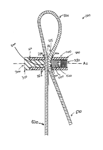
[0026] FIG. 1 shows a perspective view of an example embodiment of a
securement
apparatus 100 in operation with a retention member 500.
[0027] FIG. 2 shows a cross-section view of an example embodiment of a
securement
apparatus 100 in operation with a retention member 500.
[0028] FIG. 3A shows an example embodiment of a securing body 200 in operation
with an
engaging member 400 inserted.
[0029] FIG 3B shows another example embodiment of a securing body 200 without
an
engaging member 400.
[0030] FIG. 4 shows a perspective view of an example embodiment of two
securement
apparatus in operation with two retention members.
[0031] FIG. 5 shows a cross-section view of an example embodiment of two
securement
apparatus in operation with two retention members.
[0032] FIG. 6 shows a perspective view of another example embodiment of two
securement
apparatus in operation with one or more retention members.
[0033] FIG. 7 shows a cross-section view of another example embodiment of two
securement apparatus in operation with one or more retention members.
[0034] It will be noted that throughout the appended drawings, like features
are identified by
like reference numerals.
CAN_DMS: \135173748\1 4a
Date Recue/Date Received 2020-09-02
CA 02835531 2013-11-26
Detailed Description
[0035] Some of the conventional tie down or cable locking mechanisms may
damage the
"live" end of a retention member (i.e., portion of the retention member that
carries a load or
force). This may weaken the live end of the retention member that transfers
the load or force
and this may lead to failure. This invention may reduce point loading and or
damaging the
live section of the retention member such as cable or wire or rope.
[0036] It is also desired that a securement apparatus is easy to operate for a
user, where the
user can set the assembly into a secured (or closed) position with a simple
tool or driver such
as an Allen key or a wrench.
[0037] In addition, it is further desired that such a securement apparatus is
simple to
manufacture on an assembly line with readily available standard parts.
[0038] Note that there may be a tradeoff between cost of manufacturing and
flexibility of the
securement apparatus. In addition, conventional tie-down mechanism may be
bulky, heavy
or otherwise less desirable. Improvement is thus desired.
[0039] In the present disclosure, a securement apparatus is described, which
provides
securement for applications such as with earthquake (seismic) and wind load
and may be
relatively simple to manufacture with preferably off-the-shelf parts or
readily available
standard hardware. Furthermore the securement apparatus product may be
manufactured
at a reasonable cost.
[0040] It is noted that various connections are set forth between elements in
the following
description and in the drawings. It is noted that these connections in general
and, unless
specified otherwise, may be direct or indirect and that this specification is
not intended to be
limiting in this respect.
[0041] FIG. 1 illustrates an example embodiment of a securement apparatus 100
in
operation with a retention member 500 in accordance with one or more aspects
of this
disclosure. In particular, in FIG. 1 a securement apparatus 100 is shown
together with a
retention member 500, the securement apparatus 100 has a securing body 200
(shown in
phantom outline for easy of illustration of internal components) and an
engaging member
400. The securing body 200 is shown to have a securing member 300 on a first
end of the
210 of the securing body 200. The securing body 200 in this example embodiment
is shown
CA 02835531 2013-11-26
to have a hexagonal shape. However, it may be any shape suitable for the
purpose of the
invention. For example, the securing body 200 may be of a round, square or
oval shape. It
may also be of an irregular shape.
[0042] It is noted that various configurations of the securement apparatus 100
including any
one (or more) of the securing body 200, the securing member 300 and the
engaging member
400 are possible and the illustrations in the drawings are not meant to be
limiting. For
example, even though in the example embodiments shown, the retention member
500 does
not form part of the securement apparatus 100, in another configuration a
securement
apparatus 100, for example in a kit, may or may not include the retention
member 500. In
addition, a securing body 200 may or may not include the securing member 300
or the
engaging member 400.
[0043] Turning back to FIG.1, it is shown that the securing body 200 has a
first end 210, a
second end 220 opposite to the first end 210, a first passage 225, a second
passage 280
and an outer surface 260. The first passage 225 has two opposite facing ends:
a first side
230 and a second side 240. The first passage has an axis Al. The second
passage has an
axis A2 which may intersect first end 210 and second end 220 of the securing
body 200. Axis
Al and A2 may or may not be perpendicular. In addition, axis Al may or may not
be parallel
to the first side 230 or the second side 240 of the first passage 225. A third
passage may
also extend from the first end 210 of the securing body 200 to the first side
230 of the first
passage 225, meeting the first passage 225. The third passage may also meet
the second
passage 280. Furthermore, the first passage 225 and the second passage 280,
and
optionally with the third passage, may intersect to form a void through which
one or more
retention members may pass. The void may be of any shape or form to permit
securement
of one or more retention members in accordance with one or more aspects of the
invention.
[0044] The first passage 225 may be positioned somewhere in, or in an
embodiment close to
the middle of, the securing body 200 generally adjacent or along the axis A2,
as shown in
FIG. 1 and more clearly in FIG. 3B. However, it can also be located anywhere
else in the
securing body 200. Turning briefly to FIG. 3B, an example embodiment of a
securing body
200 without an engagement member 400 is shown. The securing body 200 comprises
a
securing member 300, which is described in detail below, at the first end 210
of the securing
body 200. As previously stated, the first passage 225 may have a first side
230 and a
second side 240. The first side 230 may be defined as the side closest to the
first end 210 of
6
CA 02835531 2013-11-26
the securing body 200. In the drawing shown in FIG. 3B, for clarity, the first
side 230 is
generally shown to be the shaded area. However, the surface area of the first
side 230 may
be smaller or larger than the shaded area shown here. The first side 230 may
have a
generally uniform surface, which may be generally smooth, and may generally
correspond to
the surface or a periphery of one or more retention members 500. That is, in
an
embodiment, the curvature or another shape of the first side 230 may match or
conform to
the curvature or another shape of the retention member 500. A retention member
500 may
be, for example, a cable, a rope, a wire, or any structure that may be capable
of transferring
a load or force and which engages within a passage of a securing body.
[0045] In another example the combination of side 230 of securing body 200 and
second
end 320 of the securing member 300 may provide a saddle for live end 520 of
the retention
member 500 that may match or conform to the curvature of live end 520.
[0046] In another example embodiment, the retention member 500 may be a steel
cable with
a generally circular or round cross-section. Accordingly, the first side 230
of the first passage
225 of the securing body 200 can have a smooth, curved (or concave) surface
corresponding
to the surface of one or more steel cables. Such a generally smooth surface
may ensure
that limited or no sharp edges, unduly small radius, or incongruent shape is
present in the
first side 230 of the first passage 225. This may prevent the securing body,
or any
component inside the securing body, from interfering with the live end of the
cable and
consequently encouraging damage or weakening the cable and leading to possible
failure.
[0047] As will be described below, a proper seat or saddle for the retention
members 500
may allow the pressure applied to the retention members 500 to be distributed
more evenly
on the live end of the retention member and thus to reduce the possibility of
excessive
stress.
[0048] Turning back to FIG.1, the securing body 220 may have a second passage
280. The
diameter of the second passage 280 may be any suitable size or dimension. In
one example
embodiment, it may have a size to fit an engaging member 400. The second
passage 280
optionally has a threaded inner surface. The second passage 280 may extend
from the
second side 240 of the first passage 225 to the second end 220 of the securing
body 200.
[0049] A securing member 300 may also form part of the securing body 200.
Alternatively, it
may be a separate entity from the securing body 200. In some embodiments, a
securing
7
CA 02835531 2013-11-26
member 300 may be secured to, attached to, integrated with, or otherwise be
made part of
securing body 200 within a passage. The attachment, integration, securement or
fixing of
the securing member 300 to the securing body 200 may be in a releasable form
so that the
securing member 300 may be taken out of the securing body 200 without damaging
either
structure. For example, the securing member 300 can take the form of a bolt or
some other
form such as a cam or a wedge and that the securing member 300 can be
releasably
threaded, pressed, pushed or sided into the securing body 200, which may be in
the form of
a nut-like or cylindrical or conical component. The securing member 300 may be
integrated
into securing body 200 in various other configurations and the possible
embodiments of the
invention should not be limited to the embodiments specifically disclosed
herein.
[0050] An engaging member 400 may also form part of the securing body 200.
Alternatively,
it may be a separate entity from the securing body 200. In some embodiments,
an engaging
member 400 may be secured to, attached to, integrated with, or otherwise be
made part of
securing body 200 within a passage. The attachment, integration, securement or
fixing of
the engaging member 400 to the securing body 200 may be in a releasable form
so that the
engaging member 400 may be taken out of the securing body 200 without damaging
either
structure. For example, the engaging member 400 can take the form of a bolt or
some other
form such as a cam or a wedge and that the engaging member 400 can be
releasably
threaded, pressed, pushed or sided into the securing body 200, which may be in
the form of
a nut-like or cylindrical or conical component. The engaging member 400 may be
integrated
into securing body 200 in various other configurations and the possible
embodiments of the
invention should not be limited to the embodiments specifically disclosed
herein.
[0051] As shown in the drawings, securing member 300 and securing body 200
appear to be
similar in size and shape to a bolt-like and a nut-like component,
respectively. However,
other lengths, sizes, or shapes of securing member 300 and/or securing body
200 may be
used in some embodiments.
[0052] In one example embodiment the securing member 300 may have a first end
310 and
a second end 320. The second end 320 may be a machined end and may have a
generally
uniform or smooth surface generally corresponding to the surface or periphery
of one or
more retention members 500. That is, the curvature of the second end 320 of
the securing
member 300 may generally match or conform to the curvature of the retention
member 500.
8
CA 02835531 2013-11-26
,
,
A retention member 500 may be for example a cable, a rope, a wire, or any
structure that
may be capable of holding a weight and retained within a passage of a securing
body.
[0053] In another embodiment, the second end 320 of the securing member 300
has a
smooth, curved (or concave), inward-facing surface that generally resembles a
somewhat C
or U shape, as shown in FIGs.1 and 3A. Together with the first side 230 of the
first passage
225, the inner surface portions of the first end 230 and the second end 320
respectively may
be contoured to provide respective concave portions that fit relatively
closely or snugly
around the outer shape (e.g. a curvature or another shape) of a retention
member 500. The
first side 230 of the first passage 225 and the second end 320 of the securing
member 300
may be manufactured in such a way so that they may form a seat or saddle for a
live end
520 of a retention member 500. The generally uniform or smooth surface of the
second end
320 generally in contact with the retention member 500 may allow the pressure,
when
secured, to be somewhat distributed evenly on the live end 520 of the
retention member 500
and thus may limit excessive stress on the live end 520. This may eliminate a
direct force or
point load on the live end 520 and may prevent or reduce weakening or damage
affecting the
performance of the securement apparatus.
[0054] A retention member 500, as described earlier, may be a wire, a rope, a
cable,
combination of cable and attachment bracket, or cable attachment bracket and
thimble, or
other suitable feature. However, it should be appreciated that a retention
member 500 is not
limited to those examples. It may be any body or structure that is capable of
resisting force
holding some mass or weight ("load") on at least one end. A retention member
500 may
have two ends 510 and 520. When connected to a load (not shown), at least one
end is
connected to the load. The end connected to a load is typically referred to as
the live end
520, and the end not connected to a load is typically referred to as the dead
end 510. As the
live end 520 is the end resisting the force or load, it may provide a
resisting force of the
system and thus is preferably strong and durable in both static and high
stress environments
situations or extreme events (e.g. earthquake, bomb blast, wind, securing an
object in transit,
or construction). The damage and/or stress to the live end 520 of a retention
member 500
should be reduced or minimized, and in particular any point or similar load
should be
eliminated or reduced. To this end, it would be preferable if a surface with
which the live end
520 comes into contact is more or less uniform or smooth, and generally
corresponds to or
matches the outer shape (e.g. a curvature shape) or periphery of the live end
520 of the
retention member 500. This way, when external pressure is applied against the
live end 520
9
CA 02835531 2013-11-26
,
of the retention member 500, the pressure may be distributed somewhat evenly
onto the live
end 520 and then transferred (in whole or in part) to the surface in contact
with the live end
520. In some cases, if a live end 520 is in close contact with the dead end
510 of the
retention member 500 along some length or portion, as shown in the example
embodiment, a
pressure applied against the dead end 510 could be (in whole or in part)
transferred onto the
live end 520 along the point or portion of contact. In such cases, it is
preferable that the
pressure or force transferred onto or applied against the live end 520 is
generally evenly
distributed along some surface of the live end 520, and may be (in whole or in
part)
transferred onto the securing body where appropriate and possible.
[0055] An engaging member 400 is also shown in FIG. 1. It may be appreciated
that an
engaging member 400 does not necessarily form part of the securement apparatus
100 or
the securing body 200. In some embodiments, an engaging member 400 may be
secured
to, attached to, integrated with, or otherwise be made part of securing body
200. The
attachment, integration, securement or fixing of the engaging member 400 to
the securing
body 200 can be in a releasable form so that the engaging member 400 may be
taken out of
the securing body 200 without damaging either structure. For example, the
engaging
member 400 can take the form of an adjustable set screw or bolt and that the
engaging
member 400 can be releasable threaded into the securing body 200, which may be
in the
form of a nut-like or cylindrical or oval like component. It may be
appreciated that the
engaging member 400 may be connected with or otherwise secured to securing
body 200 in
various other configurations and the possible embodiments of the invention
should not be
limited to the specific embodiments disclosed herein.
[0056] As shown in the drawings, engaging member 400 and securing body 200 may
be
similar in size and shape to a set screw and a nut-like component,
respectively. However,
other lengths, sizes, or shapes of engaging member 400 and/or securing body
200 may be
used in some embodiments. The engaging member 400 will be described in more
detail
below in connection with FIG. 2.
[0057] Turning now to FIG.2, which is a cross-section view of an example
embodiment of a
securement apparatus 100 with a retention member 500. It may be appreciated
that the
retention member 500 does not necessarily form part of the securement
apparatus 100, but
is included here to better illustrate the relationships between various
components of the
securement apparatus 100 when operating. Retention member 500 may have a live
end 520
CA 02835531 2013-11-26
with a weight load (not shown), and a dead end 510. Both ends 510 and 520 may
be within
or through the first passage 225. The retention member may have a loop formed
by the two
ends, though a loop is not necessary for a retention member 500 to be
functional according
to one or more aspects of the invention. On a first side 230 of the first
passage 225 and
adjacent to the first passage 225, there may be a securing member 300 threaded
or
otherwise inserted into the second passage 280 at the first side 210 of the
securing body
200; on the other side 240 of the first passage 225 and adjacent to the first
passage 225,
there may be an engaging member 400 threaded or otherwise inserted into the
second
passage 280 at the second side 220 of the securing body 200. The securing
member 300
may have a first end 310 and a second end 320. The second end 320 is shown to
be in
contact with the live end 520 of the retention member 500. Even though not
explicitly
illustrated in FIG. 2, the second end 320 of the securing member 300 may have
a generally
uniform or smooth, inward-facing surface that generally resembles a C or U
shape, and/or
that corresponds to the outer shape or periphery of the live end 520 of the
retention member
500. The second end 320 of the securing member 300 may substantially or fully
align with
the first side 230 of the first passage 225, that is, the surface of the
second end 320 and the
surface of the first side 230 may be somewhat flush with each other.
[0058] The engaging member 400 may have a first end 410 and a second end 420.
The first
end 410 of the engaging member 400 may be smooth or alternatively it may be
rough or
have a generally uneven surface. The engaging member 400 may be inserted (such
as
threaded) all the way into the second passage 280 of the securing body 200 so
that the first
end 410 of the engaging member 400 may come into contact with the dead end 510
of the
retention member 500, such as shown in FIG. 1 and FIG. 3A. The engaging member
400
may be inserted into the second passage 280 by hand or by any driver or tool
that can apply
a suitable amount of torque to the securing member 400. For example, an Allen,
hex key or
a wrench may be used to push or thread the engaging member 400 into the
securing body
200.
[0059] A user may purchase a securement package or kit for use. The securement
kit may
include the securing body 200 and a securing member 300. The securement kit
may further
include an engaging member 400 and a matching Allen/ hex key. Alternatively,
the
securement kit may not include an engaging member 400, if the engaging member
400 may
be otherwise obtained. The securement kit may further include a retention
member 500 for
use with the securement apparatus. Such a retention member 500 can for example
be a
11
CA 02835531 2013-11-26
cable, a rope or a wire. It may be made of steel, copper, iron, high-strength
fiber or any other
suitable material.
[0060] During operation, in an example embodiment, a user may first ensure
that a securing
member 300 is properly secured, attached or otherwise connected to the
securing body 200
so that the second end 320 of the securing member 300 generally or
substantially aligns with
the first side 230 of the first passage 225 of the securing body 200. The user
may use his or
her hand, or any suitable tool or driver to adjust the position of the
securing member 300
inside the securing body 200. The user next may insert a retention member 500
through the
first passage 225 so that both the live end 520 and the dead end 510 are
within the first
passage 225. The user may then use his or her hand, or any suitable tool or
driver to
secure, attach, insert or thread the engaging member 400 into the second
passage 280 of
the securing body 200 from the second end 220, so that the first end 410 of
the engaging
member 400 may be tightly or snugly secured or encouraged against the dead end
510 of
the retention member 500. The user may then connect a load to or otherwise
attach to the
live end 520 of the retention member 500, and further adjust the engaging
member 400 with
hand or any suitable tool or driver in order to fix or otherwise secure the
retention member
500 in place with a weight load or a potential load. In another example, the
retention
member 500 so secured may have a loop forming with the two ends 510 and 520.
This loop
may then be hung on or otherwise attached to another structure, such as a
wall, a cabinet, or
a ceiling. This loop may provide resistance, agility, buffer and/or
flexibility to prevent
breaking or otherwise loosening of the weight load in static or high stress
situations.
[0061] In another example this can be offered as a pre-assembled kit, where a
cable wire or
wire rope or other feature is fished or provided through the first passage 225
of the securing
body to form a retention member 500, where the live end section 520 is seated
against the
first side 230 of the first passage 225 of the securing body 200, and
optionally against
second end 320 of the securing member 300, and optionally against the dead end
section
510, which may be located next to the live end section 520. The engaging
member 400 may
be assembled inside the securing body and may be snug against the dead end
section 510.
The user then may be required to pull the cable, wire or wire rope to adjust
the length and
then may use his or her hand, tool, torque wrench or other feature to secure
engaging
member 400.
12
CA 02835531 2013-11-26
[0062] In yet another example, as shown in FIGs. 4 and 5, which demonstrate an
example
embodiment of two securement apparatus in operation with two retention
members, this
device may be used for splicing or otherwise joining two or more cables to
obtain advantages
such as a longer length. As can be seen from FIGs. 4 and 5, two retention
members, each
forming a loop secured by a securement apparatus, may be joined together to
provide longer
length. In one possible embodiment, one live end 520 can be secured or
attached to a
structure, object, fixture, wall, or a ceiling; and the other live end 520 may
also be secured or
attached to another structure, object, fixture, wall, a cabinet, or a weight
load. The two loops
may be joined, linked or intertwined together as to form a secure and reliable
connection
between the two retention members and thus between the two live ends 520 and
their
respective loads or attachments. In another embodiment, each of two live ends
520 may be
secured or otherwise attached to an objection in motion, such as an airplane
or a vehicle.
That is, the two objects in motion may be reliably and securely connected with
the
embodiment shown in FIGs. 4 and 5. One possible usage scenario may be that one
aircraft
needs to deliver and/or transfer fuel to another aircraft, and it may be
necessary to tie one
aircraft to the other during the fueling process. The two securement apparatus
linked
together by the loops of retention members may provide the appropriate
resistance, agility,
buffer and/or flexibility in such unusual and high stress situations. The
figures are provided
for illustrative purpose only; applications are not limited to the
illustrations shown.
[0063] In still another example, as demonstrated in FIGs. 6 and 7, which show
another
example embodiment of two securement apparatus in operation, two or more
securement
apparatus may be used to secure one or more retention members, where the
retention
members may go through a first passage of each securement apparatus. The
figures are
provided for illustrative purpose only; applications are not limited to the
illustrations shown.
[0064] Such application of a securement apparatus 100 may require minimum
torque or
force (applied by at least the engaging member) to fix a retention member 500
(e.g. a steel
cable) with a weight load onto structures and to provide an industry standard
safety factor
based on the minimum breaking strength of the retention member 500. In
addition, since
there is limited or no sharp edge or small radius in the surface area in
contact with the live
end 520 of the retention member 500, the securement apparatus 100 may prevent
the
possibility of biting into the retention member 500, causing damage or
weakening the live
end 520 and leading to possible failure of the securement apparatus.
13
CA 02835531 2013-11-26
[0065] In one example embodiment according to one or more aspects of the
invention, using
a nut-like component as the securing body, a bolt as the securing member, a
set screw as
the engaging member, and a cable as the retention member, enough force may be
applied to
retain generally at least one of the dead end and the live end of the cable.
Force of the
bolt/set screw may be transferred, preferably evenly, by the dead end to the
live end of the
cable seated on the feature or saddle created by the generally uniform or
smooth, curved
surfaces of the bolt and the nut-like component in the first passage. This may
reduce any
direct force or point load on the live end and could prevent weakening or
damage affecting
the performance of the securement apparatus when connected to a load.
[0066] In another example embodiment according to one or more aspects of the
invention, a
securement apparatus kit may be packaged and provided. The kit could include
an
instruction manual including instructions in appropriate languages to teach a
user how to use
the securement apparatus. The kit may include two or more of: at least one
securing body,
at least one securing member, at least one engaging member, and/or at least
one retention
member. The kit may further include any or no appropriate tools or drivers for
use with the
securement apparatus. In a preferred embodiment, the securing body may have a
securing
member pre-inserted into the securing body. However, a securing member may be
separate
from the securing body, and a user could choose to install the securing member
and the
securing body together with hands and/or suitable tools. In yet another
embodiment, the kit
may include at least one securing body 200 with a round or oval-shaped first
passage 225,
and separate from the securing body 200, the kit may also include multiple
engaging
member 400 or securing member 300, each securing member 300 may have a
uniquely
shaped second end 320. This is so that the user may pick the desired securing
member 300
with a desired shape at the second end 320 in order to fit a retention member
500. The kit in
this scenario may further include different kinds of retention members 500
and/or different
engaging members 400.
MANUFACTURING OF THE SECUREMENT APPARATUS
[0067] A manufacturing process of a securement apparatus according to one or
more
aspects of the invention is described next. The ordering of steps may be
changed or varied
as needed. A first step in the manufacturing process may be to insert, attach,
or otherwise
secure a securing member 300 into a securing body 200. A second step is to
form a
passage or a hole through the securing body 200, which may become first
passage 225,
14
CA 02835531 2013-11-26
such that the passage or the hole may be formed through both the securing body
200 and
part of the securing member 300, destroying the end of the securing member 300
to form a
new second end 320 of the securing member 300. Optionally the passage or hole
is formed
so that the second end 320 of the securing member 300 may have a generally
uniform or
smooth, curved (or concave), inward-facing surface that generally resembles a
C or U shape,
such as a saddle or seat that generally corresponds to the outer shape or
periphery of the
live end 520 of a retention member 500. The second end 320 of the securing
member 300
may also substantially or generally align with the first side 230 of the first
passage 225, that
is, the surface of the second end 320 and the surface of the first side 230
may be somewhat
flush with each other. In a preferred embodiment, the first side 230 of the
first passage 225
and the second end 320 of the securing member 300 are machined in such a way
that the
inner surface portions of the first end 230 and the second end 320
respectively are contoured
to provide respective concave portions that fit relatively closely or snugly
around the outer
shape (e.g. a curvature shape) or periphery of a retention member 500. In some
other
examples, the second end 320 of the securing member 300 and/or the first side
230 of the
first passage 225 of the securing body 200 can also take the shape of a quoit,
a torus, a
toroid, a quonset, an oblate spheroid, prolate spheroid, a segment of a
sphere, a spherical
wedge, an arch, a camber, a kidney, obround, oval, a pyriform, a crescent, or
any other
suitable shape that has a smooth, gradual curve.
[0068] In one example embodiment, during the forming of the first passage 225,
the
machining process may permanently or semi-permanently alters an original part
or end of the
securing member 300, forming a new end 320 of the securing member 300, such
that the
securing member 300 may be permanently or semi-permanently molded to, attached
to or
otherwise fixed to the securing body 200. During this process, the securing
member 300
may lose part of its original functionality. For example, in one embodiment,
the securing
member 300 may be a bolt, which may have its end permanently or semi-
permanently
altered, or may even be destroyed, by the machining process, such that the
bolt may not
function properly (i.e., serving its original, typical purpose of a fastener)
outside of the
securement apparatus. In another embodiment, the securing member 300 may be a
screw,
which may have its end altered by the machining process in the forming of a
first passage
225 of the securing body 200. Through the machining process which may alter an
original
part or end of a securing member 300, a new end 320 of the securing member 300
is
formed. This new end 320 may have a generally uniform or smooth surface
afforded by the
CA 02835531 2013-11-26
=
machining process. Somewhat flush with the first side 230 of the formed first
passage 225,
the new end 320 of the securing member 300 may be part of a feature, a seat or
a saddle
that generally conforms to a periphery or outer shape of one or more retention
members 500.
A process of forming a passage or a hole in a securing body 200 in which an
original part or
end of a securing member 300 is permanently or semi-permanently altered may
thus
encourage the securing body 200 to be crimped, welded, glued (using chemical
agents),
damaged, destroyed or altered to hold the securing member 300 in place, where
the formed
passage may intersect with an end 320 of the securing member 300 to define a
generally
uniform or smooth surface.
[0069] In another example, securing member 300 may be seated against surface
210 of
securing body 200 and the assembly may be punched or crimped together at one
or multiple
locations to secure in place securing member 300 permanently before or after
the machining
process for creating passage 225.
[0070] In yet another example, securing member 300 can be part of the securing
body 200.
This may be done through either machining process, molding/casting process and
or
combination of both machining and molding/casting processes. In such case side
230 of
passage 225 of securing body 200 and end 320 of securing member 300 may become
one
part.
[0071] The forming of the passage or hole may be done by drilling, plasma,
laser-cutting,
die-cast, machining or any other suitable means of forming a passage through
an object.
[0072] In one example embodiment, each component in a securement apparatus 100
may
be sourced from off-the-shelf products or readily available hardware. For
example, the
securing body 200 may be a nut or a coupling nut, the securing member 300 may
be a bolt
or screw or a set screw , and the engaging member 400 may be a set screw or
any type of
bolt or set screw. All of these components may be obtained easily and are
inexpensive from
many suppliers.
[0073] The embodiments of the present disclosure described above are intended
to be
examples only. Alterations, modifications and variations to the disclosure may
be made
without departing from the intended scope of the present disclosure. In
particular, selected
features from one or more of the above-described embodiments may be combined
to create
alternative embodiments not explicitly described. All values and sub-ranges
within disclosed
16
, ,
'
. _
ranges are also disclosed. The subject matter described herein intends to
cover and
embrace all suitable changes in technology.
17
CA 2835531 2020-01-15