Note: Descriptions are shown in the official language in which they were submitted.
CA 2835822 2017-04-26
SYSTEMS AND METHODS FOR SEPARATING COMPONENTS OF A SLURRY
[0001] This paragraph intentionally left blank
Field of the Disclosure
[0002] The present disclosure is directed to systems and methods for
removing fluid from
a slurry, and more particularly to systems and methods that include injecting
a displacing fluid
into the slurry to displace a liquid contained therein.
Background of the Disclosure
[0003] A slurry may refer to any suitable heterogeneous mixture of solid
particles in a
liquid. Illustrative, non-exclusive examples of slurries include dispersions,
suspensions,
and/or colloids. Slurries may include heterogeneous mixtures, in which the
solid particles
may be physically distributcd within the liquid, but in which at least a
portion of the solid
particles may separate from the liquid naturally over time due to various
spontaneous, or
naturally occurring, separation mechanisms. Illustrative, non-exclusive
examples of such
separation mechanisms include settling, agglomeration, aggregation,
precipitation,
coalescence, sedimentation, creaming, and/or other separation processes that
may be governed
by gravitational, electrostatic, interfacial, and/or other naturally occurring
forces.
[0004] However, for certain slurries, these spontaneous separation
processes may be
extremely slow and/or may proceed for a period of time, after which a
separation rate may
decrease significantly and/or separation may effectively cease. Additionally,
slurries also
may include heterogeneous mixtures, in which at least a portion of the solid
particles may
remain suspended within the liquid indefinitely due to electrostatic repulsion
among the solid
particles that may resist the above separation mechanisms. In addition,
capillary forces
between the liquid and the solid particles may further slow the separation
process.
[0005] In a number of industrial processes, illustrative, non-exclusive
examples of which
include oil production, separation of hydrocarbons from oil sands, and/or
dewatering of mine
tailings, it may be desirable to separate at least a portion of the liquid
component of the slurry
from the solid particles. For certain slurry compositions, separation of the
solid and liquid
- 1 -
CA 02835822 2013-11-12
WO 2012/177327 PCT/US2012/036553
components of the slurry may be accomplished by making use of the above-
described
naturally occurring separation mechanisms. However, a separation rate obtained
using these
naturally occurring separation mechanisms may be significantly slower than a
separation rate
that may be desired and/or needed for efficient and/or economical operation of
the separation
process. In addition, natural separation of the solid and liquid components
simply may not
occur for other slurry compositions.
[0006] While a number of processes for separating the components of a
mixture exist,
these processes may not be effective and/or economical for separating slurry
components.
This may be due to a variety of factors, illustrative, non-exclusive examples
of which may
include the abrasive nature of some solid particles and the expense associated
with designing
and/or constructing valves and/or seals that may resist damage and/or wear due
to slurry flow
therethrough, the high viscosity of some slurries, and/or plugging of
filtration apparatus by
the solid particles.
[0007] As an illustrative, non-exclusive example, pressure-driven
membrane filtration
processes may be utilized to separate components of a mixture of solid
particles and a liquid,
or a solid-liquid mixture. These processes may include pressurizing a fluid
that includes
particulate material and contacting the fluid-particulate mixture with a first
side of a porous
surface that has a reduced pressure on a second side. Driven by the pressure
differential
across the porous surface, the liquid will flow therethrough. However, the
solid components
that are too large to pass through the porous surface will remain on the first
side of the porous
surface.
[0008] While such pressure-driven membrane filtration processes may be
effective at
separating the components of the solid-liquid mixture, they also have several
limitations. As
an illustrative, non-exclusive example, the porous surface may become plugged
and/or the
pores of the porous surface may become occluded due to the accumulation of
solid particles
on the first side of the porous surface, resulting in the formation of a
filter cake. While this
plugging may be reduced and/or eliminated through replacement of the porous
surface with a
new porous surface and/or by backflow through the filtration equipment, both
of these
processes may require that the filtration system be taken offline for a
period, resulting in lost
time and/or a quasi-batch separation process.
[0009] In addition to backflowing, the buildup of a filter cake may be
reduced by flowing
the solid-liquid mixture in a direction that is generally parallel to the
porous surface. This
parallel flow may result in shear forces that may erode the filter cake and/or
substantially
- 2 -
CA 02835822 2013-11-12
WO 2012/177327 PCT/US2012/036553
reduce formation. However, even when the formation of the filter cake is
significantly
reduced, the capillary forces between the liquid and the solid particles may
prevent the
separation process from proceeding at the desired separation rate.
Summary of the Disclosure
[0010] Systems and methods are disclosed for removing fluid from a slurry
that includes
a slurry fluid and a plurality of solid particles. These systems and methods
may include
flowing a slurry stream that includes the slurry through a slurry conduit, and
injecting a
displacing fluid through a first perforated region that is in fluid
communication with the
slurry conduit. The systems and methods may further include displacing at
least a portion of
the slurry fluid from the slurry through a second perforated region that is in
fluid
communication with the slurry conduit, to produce a displaced fluid stream,
which may
include the displaced portion of the slurry fluid and/or a portion of the
injected displacing
fluid.
[0011] In some embodiments, the slurry conduit may be defined by a body.
In some
embodiments, a single surface of the body may define the slurry conduit. In
some
embodiments, multiple surfaces of the body may define the slurry conduit. In
some
embodiments, the slurry conduit may be at least one of circular, annular, and
rectilinear. In
some embodiments the slurry conduit may include an annular space formed by a
pipe-in-pipe
arrangement. In some embodiments, the systems and methods may include the use
of an
outer housing to contain at least a portion of the streams and/or components
that define the
slurry conduit. In some embodiments, the outer housing may surround the slurry
conduit in a
pipe-in-pipe-in-pipe arrangement.
[0012] The first perforated region and/or the second perforated region,
which also may be
referred to herein as the perforated regions, may include any suitable
structure configured to
provide fluid communication between a region internal to the slurry conduit
and a region
external to the slurry conduit. In some embodiments, the perforated regions
may include a
porous material. In some embodiments, the perforated regions may include one
or more
perforations which optionally may be in fluid communication with one or more
ports.
[0013] The systems and methods also may include producing a product
slurry stream
from the slurry conduit, separating the components of the displaced fluid
stream, separating
the components of the product slurry stream, and/or recycling a portion of one
or more of the
streams. In some embodiments, the systems and methods disclosed herein may be
utilized as
-3 -
CA 02835822 2013-11-12
WO 2012/177327 PCT/US2012/036553
part of a mine tailings dewatering system. In some embodiments, the systems
and methods
disclosed herein may be utilized as part of a solvent extraction process. In
some
embodiments, the systems and methods disclosed herein may be utilized to
recover
hydrocarbons from oil sands.
Brief Description of the Drawings
[0014] Fig. 1 is a schematic representation of an illustrative, non-
exclusive example of
systems according to the present disclosure for separating the components of a
slurry.
[0015] Fig. 2 is a transverse cross-sectional view of a less schematic
but still illustrative,
non-exclusive example of a system according to the present disclosure for
separating the
components of the slurry that includes a pipe-in-pipe-in-pipe arrangement.
[0016] Fig. 3 is a schematic view of the system of Fig. 2 being operated
in a forward-flow
configuration.
[0017] Fig. 4 is a schematic view of the system of Fig. 2 being operated
in a backflow
configuration.
[0018] Fig. 5 is a less schematic view of another illustrative, non-
exclusive example of a
system according to the present disclosure for separating the components of
the slurry that
includes a pipe-in-pipe-in-pipe arrangement and plurality of fluid injection
and/or fluid
production ports.
[0019] Fig. 6 is a transverse cross-sectional view of a system similar to
the system of Fig.
2 but including a specialized region.
[0020] Fig. 7 is a transverse cross-sectional view of another
illustrative, non-exclusive
example of a system according to the present disclosure for separating the
components of the
slurry that includes a pipe-in-pipe arrangement and one or more fluid
injection and/or fluid
production ports.
[0021] Fig. 8 is a schematic representation of another illustrative, non-
exclusive example
of a system according to the present disclosure for separating the components
of the slurry
that includes a pipe-in-pipe arrangement and a barrier.
[0022] Fig. 9 is a schematic representation of another illustrative, non-
exclusive example
of a system according to the present disclosure for separating the components
of the slurry
that includes a planar system geometry and substantially opposed perforated
regions.
- 4 -
CA 02835822 2013-11-12
WO 2012/177327 PCT/US2012/036553
[0023] Fig. 10 is a schematic representation of another illustrative, non-
exclusive
example of a system according to the present disclosure for separating the
components of the
slurry that includes a planar system geometry and substantially offset
perforated regions.
[0024] Fig. 11 is a schematic representation of a dewatering system
according to the
present disclosure.
[0025] Fig. 12 is a schematic representation of a solvent extraction
system according to
the present disclosure.
[0026] Fig. 13 is a less schematic but still illustrative, non-exclusive
example of a solvent
extraction system according to the present disclosure.
[0027] Fig. 14 is a flowchart depicting methods according to the present
disclosure for
separating slurry components.
Detailed Description and Best Mode of the Disclosure
[0028] Fig. 1 provides a schematic cross-sectional view of illustrative,
non-exclusive
examples of a slurry separation assembly 10, which also may be referred to as
an apparatus
for removing a liquid from a slurry, according to the present disclosure.
Slurry separation
assembly 10 includes a body 20 that may include one or more elements 22, 22',
and/or
regions 22, 22', that may define at least a portion of a slurry conduit 30.
Slurry conduit 30 is
in fluid communication with a first perforated region 40 and a second
perforated region 50.
A slurry stream 60, including a slurry 62 comprising a slurry liquid 64 and a
plurality of solid
particles 66, is supplied to slurry conduit 30; and a product slurry stream
70. A displacing
fluid stream 80, including displacing fluid 82, may be supplied to at least
one of first
perforated region 40 and second perforated region 50, and a displaced fluid
stream 90,
including displacing fluid 82 and a portion of slurry liquid 64, may be
produced from the
other of first perforated region 40 and second perforated region 50. An outer
housing 95 may
contain, surround, house, or otherwise confine at least a portion of the
plurality of
components that define slurry separation assembly 10 and/or the plurality of
streams that are
associated with slurry separation assembly 10.
[0029] Slurry separation assembly 10 may be configured to inject
displacing fluid 82 into
slurry 62 to displace, substitute, replace, and/or otherwise remove at least a
portion of slurry
liquid 64 from the slurry. The displaced, substituted, replaced, and/or
removed portion of
slurry liquid 64 may exit the slurry separation assembly in displaced fluid
stream 90 and, as
- 5 -
CA 02835822 2013-11-12
WO 2012/177327 PCT/US2012/036553
discussed in more detail herein, thereafter optionally may receive subsequent
processing,
purification, separation, and/or refining. Slurry separation assembly 10 may
utilize a
pressure-driven displacement and/or separation mechanism to flow, or force,
displacing fluid
82 into at least a portion of an interstitial, or void, space present between
adjacent solid
particles of slurry 62, which may increase a separation rate for the
separation of slurry liquid
64 from solid particles 66. The pressure within the separation assembly also
may control a
physical state, or phase, of the fluids contained therein, such as slurry
liquid 64 and/or
displacing fluid 82.
[0030] It is within the scope of the present disclosure that slurry
separation assembly 10
may be utilized for a variety of purposes. As an illustrative, non-exclusive
example, slurry
liquid 64 may contain or include one or more materials that are to be
recovered from slurry
62, and slurry separation assembly 10 may increase the rate of recovery and/or
decrease the
costs associated with recovery of the materials. Similarly, solid particles 66
may contain or
include one or more materials that are to be recovered from slurry 62, and
slurry separation
assembly 10 may increase the rate of recovery and/or decrease the costs
associated with
recovery of the materials. As another illustrative, non-exclusive example, it
may be
necessary to decrease a proportion of slurry 62 that includes slurry liquid 64
prior to disposal,
storage, and/or subsequent processing of the slurry and/or solid particles 66
contained therein,
and the slurry separation assembly may decrease the time and/or costs
associated with this
processing.
[0031] As discussed in more detail herein, it is within the scope of the
present disclosure
that displacing fluid 82 may be selected such that it is readily separable
from slurry liquid 64
and/or solid particles 66. Thus, separation of displacing fluid 82 from
displaced fluid stream
90 to produce a purified, pure, or substantially pure slurry liquid 64 that
does not include, or
includes a smaller proportion of, solid particles 66 may be simpler, faster,
and/or more
economical than direct separation of slurry liquid 64 from slurry 62.
Similarly, separation of
displacing fluid 82 from solid particles 66 to produce dry, or substantially
dry, solid particles
that do not include, or include a lesser proportion of, slurry liquid 64 may
be simpler, faster,
and/or more economical than direct separation of slurry liquid 64 from slurry
62. As an
illustrative, non-exclusive example, it is within the scope of the present
disclosure that
displacing fluid 82 may include a gaseous displacing fluid, a displacing fluid
with a boiling
point that is significantly different from a boiling point of slurry liquid
64, a displacing fluid
with a low boiling point, a displacing fluid with a lower affinity for solid
particles 66 than
- 6 -
CA 02835822 2013-11-12
WO 2012/177327 PCT/US2012/036553
slurry liquid 64, and/or a supercritical displacing fluid. These illustrative
displacing fluids
may facilitate simpler, faster, and/or more economical separation of the
components of
product slurry stream 70 and/or displaced fluid stream 90.
[0032] As discussed in more detail herein, slurry 62 may include any
suitable
heterogeneous mixture of slurry liquid 64 and solid particles 66,
illustrative, non-exclusive
examples of which include dispersions, suspensions, and/or colloids. It is
within the scope of
the present disclosure that slurry 62 may include any suitable proportion,
percentage, or ratio
of slurry liquid to solid particles. As an illustrative, non-exclusive
example, slurry 62 may
include 1 to 99 wt% solid particles, optionally including 1-10 wt%, 10-20 wt%,
20-40 wt%,
40-60 wt%, 60-80 wt%, 80-90 wt%, 90-99 wt%, 25-50 wt%, 50-75 wt%, 25-75 wt%,
70-90
wt%, and/or any suitable combination of the above proportions.
[0033] It is within the scope of the present disclosure that slurry
liquid 64, which also
may be referred to as liquid 64 or slurry fluid 64, may include any suitable
liquid, illustrative,
non-exclusive examples of which include water, brine, hydrocarbons, oil,
bitumen, bitumen
dissolved in a hydrocarbon solvent, tar, alcohols, solvents, hydrocarbon
solvents, and/or
solutions. When slurry liquid 64 includes a hydrocarbon solvent, it is within
the scope of the
present disclosure that the hydrocarbon solvent may include (but is not
required in all
embodiments to include) a molecular weight of less than 200 grams/mole,
illustrative, non-
exclusive examples of which include molecular weights of less than 190
grams/mole, less
than 180 grams/mole, less than 171 grams/mole, less than 170 grams/mole, less
than 160
grams/mole, or less than 150 grams/mole.
[0034] Similarly, solid particles 66 may include any suitable material,
illustrative, non-
exclusive examples of which include sand, clay particles, mine tailings,
and/or soil. It is
within the scope of the present disclosure that each of the solid particles
may include a
characteristic dimension, illustrative, non-exclusive examples of which
include any suitable
diameter, radius, effective diameter, effective radius, and/or maximum extent
or dimension.
It is further within the scope of the present disclosure that at least 30 wt%
of the solid
particles with a characteristic dimension of less than 44 microns also have a
characteristic
dimension of less than 10 microns, and optionally that at least 40 wt%, at
least 50 wt%, at
least 60 wt%, or at least 70 wt% of the solid particles with a characteristic
dimension of less
than 44 microns also have a characteristic dimension of less than 10 microns.
[0035] Slurry stream 60 may be supplied to slurry separation assembly 10
and/or slurry
conduit 30 at any desired volumetric and/or mass flow rate. As an
illustrative, non-exclusive
- 7 -
CA 02835822 2013-11-12
WO 2012/177327 PCT/US2012/036553
example, it is within the scope of the present disclosure that slurry stream
60 may be supplied
to the slurry separation assembly at a flow rate that is sufficiently low to
produce a laminar
flow profile for the slurry stream within the slurry conduit, which may
decrease a potential
for viscous fingering of the displacing fluid as it flows between the first
perforated region and
the second perforated region. However, it is also within the scope of the
present disclosure
that slurry stream 60 may be supplied to the slurry separation assembly at a
flow rate that is
sufficiently high to produce a turbulent flow profile for the slurry stream
within the slurry
conduit. Such a turbulent flow profile may increase mixing between the
displacing fluid
stream and thc slurry stream and/or decrease a buildup of a filter cake on the
perforated
region(s).
[0036] Body 20, including elements or regions 22, 22', may include any
suitable structure
configured to define at least a portion of slurry conduit 30 and may include a
single,
monolithic structure, a composite structure, and/or a plurality of independent
structures. As
an illustrative, non-exclusive example, elements or regions 22 and 22' may be
portions of a
single, monolithic body 20, illustrative, non-exclusive examples of which
include any
suitable tube, pipe, or other flow conduit. As another illustrative, non-
exclusive example,
elements or regions 22 and 22' may comprise separate portions, surfaces,
and/or components
of a composite body 20 and may be operatively attached to one another to form
the composite
body in any suitable manner. As yet another illustrative, non-exclusive
example, elements or
regions 20 and 20' may each form a portion of substantially separate,
distinct, and/or
independent structures, illustrative, non-exclusive examples of which include
a pipe-in-pipe
arrangement and/or a parallel pipe arrangement.
[0037] As discussed in more detail herein, slurry conduit 30 may be
defined at least
partially by body 20, including elements or regions 22 and 22', which may
include a single,
monolithic body, a composite body, and/or a plurality of independent
structures. It is within
the scope of the present disclosure that slurry conduit 30 may include any
suitable shape,
illustrative, non-exclusive examples of which include elongate shapes that
include a
substantially uniform transverse cross-sectional shape. Illustrative, non-
exclusive examples
of transverse cross-sectional shapes for slurry conduit 30 according to the
present disclosure
include circular, annular, rectilinear, and/or any suitable combination of
these shapes, such as
circular and/or rectilinear shapes with included circular and/or rectilinear
voids.
[0038] It is within the scope of the present disclosure that first
perforated region 40
and/or second perforated region 50, which optionally may be referred to as
first perforated
- 8 -
CA 02835822 2013-11-12
WO 2012/177327 PCT/US2012/036553
surface 40 and second perforated surface 50, first porous region 40 and second
porous region
50, and/or may be referred to more generally as perforated regions and/or
perforated surfaces,
may include one or more perforations 42, 52, which also may be referred to as
one or more
fluid flow pathways 42, 52 and/or one or more pores 42, 52. As illustrative,
non-exclusive
examples, the perforated regions may include any suitable wire mesh, metal
screen, sintered
metal, porous structure, porous ceramic, cemented rock, perforated metal,
hole, filter media,
packed bed, surface filter, and/or depth filter.
[0039] It is within the scope of the present disclosure that, as
discussed in more detail
herein, one or more of the perforations associated with the perforated regions
may be in fluid
communication with and/or form a portion of a flow port. This may include a
single
perforation that is in fluid communication with a single flow port, a
plurality of perforations
that are in fluid communication with a single flow port, a single perforation
that is in fluid
communication with a plurality of flow ports, and/or a plurality of
perforations that are in
fluid communication with a plurality of flow ports.
[0040] Perforated regions 40 and 50 may be present in any suitable location
along,
within, and/or on body 20, elements or regions 22, 22', and/or slurry conduit
30. As an
illustrative, non-exclusive example, and as shown in solid lines in Fig. 1,
first perforated
region 40 may be generally, or substantially, opposed to, across from, spaced
apart in a single
direction (such as a direction that is perpendicular to a flow direction of
slurry stream 60)
from, and/or aligned with second perforated region 50. However, and as shown
in dashed
lines in Fig. 1, it is also within the scope of the present disclosure that
first perforated region
40 may be offset from and/or spaced apart in two or more directions (such as
the direction
that is perpendicular to the flow direction of slurry stream 60 and a
direction that is parallel to
the flow direction of slurry stream 60) from second perforated region 50.
[0041] It is within the scope of the present disclosure that first
perforated region 40
and/or second perforated region 50 may include any suitable scope, size,
and/or extent along,
within, and/or on body 20 and/or slurry conduit 30. As an illustrative, non-
exclusive
example, perforated regions 40 and 50 may be present in one or more discrete
locations along
body 20 and/or slurry conduit 30, as shown in Fig. 1. However, it is also
within the scope of
the present disclosure that the perforated regions may be continuous, or at
least substantially
continuous, along, within, and/or on body 20 and/or slurry conduit 30. It is
further within the
scope of the present disclosure that first perforated region 40 and/or second
perforated region
50 may include a plurality of spaced-apart perforated regions.
- 9 -
CA 02835822 2013-11-12
WO 2012/177327 PCT/US2012/036553
[0042] It is within the scope of the present disclosure that first
perforated region 40
and/or second perforated region 50 may form a portion of body 20 (such as when
first
perforated region 40 and/or second perforated region 50 and body 20 form a
monolithic
structure). However, it is also within the scope of the present disclosure
that first perforated
region 40 and/or second perforated region 50 may include a separate structure
that is
associated with, in fluid communication with, and/or operatively attached to
body 20. This
may include perforated regions that may be configured to be permanently, or
substantially
permanently attached to body 20, as well as perforated regions that may be
configured to be
selectively removed, or otherwise separated from, body 20, such as for repair,
replacement,
and/or cleaning.
[0043] Perforations 42, 52 may include any suitable pore, hole, and/or
porous structure,
may be of any suitable size and/or extent, and may form a periodic, or
systematic, structure
and/or may be located randomly within perforated regions 40, 50. Perforations
may include a
characteristic dimension, such as a characteristic diameter, a characteristic
radius, and/or
characteristic pore size. It is within the scope of the present disclosure
that this characteristic
dimension may be configured, selected, chosen, and/or otherwise defined based,
at least in
part, on the characteristic dimension of the solid particles in (or expected
to be in) slurry 66.
As an illustrative, non-exclusive example, this characteristic dimension may
be selected to
prevent at least 90 wt% of the solid particles from passing through
perforations 42, 52,
optionally including a characteristic dimension that may be selected to
prevent at least 92
wt%, at least 94 wt%, at least 96 wt%, at least 98 wt%, at least 99 wt%, at
least 99.5 wt%, or
at least 99.9 wt% of the solid particles from passing through perforations 42,
52.
[0044] Additionally or alternatively, it is also within the scope of the
present disclosure
that the characteristic dimension of the perforations may be selected to
permit a certain size,
size range, and/or proportion of the solid particles to pass therethrough. As
an illustrative,
non-exclusive example, the characteristic dimension of the perforations may be
selected to
permit at least 30 wt% of the solid particles that are less than 1 micron in
diameter to pass
therethrough, including permitting at least 40 wt%, at least 50 wt%, at least
60 wt%, or at
least 70 wt% of the solid particles that are less than 1 micron in diameter to
pass
therethrough.
[0045] Displacing fluid stream 80 may include any suitable displacing
fluid 82 that may
be injected into the slurry stream and may expel, eject, force out, or
otherwise displace slurry
liquid 64 from slurry stream 60 and/or slurry 62. Illustrative, non-exclusive
examples of
- 10 -
CA 02835822 2013-11-12
WO 2012/177327 PCT/US2012/036553
displacing fluids 82 according to the present disclosure include a gas phase
fluid, a vapor
phase fluid, a liquid phase fluid, a supercritical fluid, and/or a dense
supercritical fluid,
illustrative, non-exclusive examples of which include water, brine,
hydrocarbons, solvents,
alcohols, air, nitrogen, steam, methane, natural gas, propane, butane,
dimethylether, and/or
carbon dioxide.
[0046] When displacing fluid 82 includes hydrocarbons, it is within the
scope of the
present disclosure that the displacing fluid may include at least 30 wt%, at
least 40 wt%, at
least 50 wt%, at least 60 wt%, or at least 70 wt% hydrocarbons and that the
hydrocarbons
may include an average molecular weight of 200 grams/mole or less, 175
grams/mole or less,
150 grams/mole or less, 125 grams/mole or less, 100 grams/mole or less, 90
grams/mole or
less, 80 grams/mole or less, 70 grams/mole or less, 60 grams/mole or less, 50
grams/mole or
less, 40 grams/mole or less, or 30 grams/mole or less, although hydrocarbon
proportions of
less than 30 wt%, as well as hydrocarbon molecular weights of greater than 200
grams/mole
are also within the scope of the present disclosure.
[0047] When displacing fluid 82 includes carbon dioxide, it is within the
scope of the
present disclosure that the carbon dioxide may be present in a gaseous and/or
in a
supercritical state. In addition, the carbon dioxide may comprise at least 25
wt%, at least 30
wt%, at least 35 wt%, at least 40 wt%, at least 45 wt%, at least 50 wt%, at
least 55 wt%, at
least 60 wt%, at least 65 wt%, at least 70 wt%, or at least 75 wt% of the
displacing fluid,
although proportions of less than 25 wt% carbon dioxide are also within the
scope of the
present disclosure.
[0048] Displaced fluid stream 90 may include any suitable fluids that may
be expelled,
ejected, forced out, removed, or otherwise displaced from slurry 62 through
the displacing
action of displacing fluid stream 80 and/or due to other factors.
Illustrative, non-exclusive
examples of other factors according to the present disclosure include pressure-
driven
separation of the components of slurry 62, diffusion-driven separation of the
components of
slurry 62, and/or gravitational forces. Typically, displaced fluid stream 90
will include
displacing fluid 82, and a lower concentration of slurry liquid 64 than was
present before the
displacing fluid was introduced into the slurry. As discussed herein, the
displaced fluid
stream may include some of the solid particles 66 of slurry 62, although this
typically will be
limited to fine particles.
[0049] Product slurry stream 70 may include any suitable portion and/or
fraction of the
components of slurry stream 60 and/or displacing fluid stream 80 that are not
removed from
- 11 -
CA 02835822 2013-11-12
WO 2012/177327 PCT/US2012/036553
slurry separation assembly 10 in displaced fluid stream 90. This may include a
portion of
solid particles 66 that does not pass through first perforated region 40
and/or second
perforated region 50, a portion of slurry liquid 64 that is not displaced from
slurry 62 by
displacing fluid 82, and/or a portion of displacing fluid 82 that is not
removed from slurry 62
in displaced fluid stream 90. The product slurry stream may additionally or
alternatively be
described as containing a product, or composite, slurry 62' that includes
solid particles 66, as
well as slurry liquid 64 and displacing fluid 82.
[0050] Outer housing 95 may include any suitable structure configured to
contain,
surround, house, or otherwise confine at least a portion of the plurality of
components that
define slurry separation assembly 10 and/or at least a portion of the
plurality of streams that
are associated with slurry separation assembly 10. This may include any
suitable tube, pipe,
conduit, and/or cover, illustrative, non-exclusive examples of which are
discussed in more
detail herein. It is within the scope of the present disclosure that outer
housing 95 may
include a fluid impervious, non-perforated, and/or non-porous outer housing
95. It is also
within the scope of the present disclosure that outer housing 95 may include
one or more flow
ports that may provide fluid communication between a region internal to the
outer housing
and a region external to the outer housing. Similar to elements 22, 22' of
body 20, housing
95 also may include one or more elements, or regions that form the housing, or
portions
thereof. This is schematically illustrated in Fig. 1 with housing region 96
and 96'.
[0051] It is within the scope of the present disclosure that slurry
separation assembly 10
may be configured, designed, or otherwise adapted to maintain a target, or
desired, pressure
differential between two or more of the streams associated with slurry
separation assembly
10. As an illustrative, non-exclusive example, displacing fluid stream 80 may
be supplied to
a perforated region and/or injected into slurry stream 60 and/or slurry
conduit 30 at an
injection pressure that is higher than a pressure of the slurry stream and/or
at a pressure that is
higher than a pressure within the slurry conduit. As another illustrative, non-
exclusive
example, displaced fluid stream 90 may be produced from a perforated region at
a displaced
fluid pressure that is less than the pressure of the slurry stream and/or that
is less than the
pressure within the slurry conduit. As yet another illustrative, non-exclusive
example, a
pressure of slurry stream 60 may be maintained to be greater than a pressure
of product slurry
stream 70. This may include maintaining a pressure differential between slurry
stream 60
and product slurry stream 70 to produce a desired, or target, flow rate of
slurry stream 60
- 12 -
CA 02835822 2013-11-12
WO 2012/177327 PCT/US2012/036553
through slurry conduit 30 and/or to maintain a desired, or target, pressure,
or range of
pressures, within the slurry conduit.
[0052] It is also within the scope of the present disclosure that, as
shown in dashed lines
in Fig. 1, the flow of displacing fluid stream 80 and displaced fluid stream
90 may be
reversed. Thus, the displacing fluid stream may be supplied to first
perforated region 40 or to
second perforated region 50, including being supplied to first perforated
region 40 for a
period of time and subsequently being supplied to second perforated region 50
for a period of
time. As discussed in more detail herein, such a forward flow followed by
backflow
configuration may decrease a potential for clogging, plugging, and/or
occlusion of
perforations 42, 52 of perforated regions 40, 50 by solid particles 66.
[0053] Less schematic but still illustrative, non-exclusive examples of
slurry separation
assemblies according to the present disclosure are shown in Figs. 2-10. Figs.
2-6 illustrate
several variations on an embodiment in which elements or regions 22 and 22',
including first
perforated region 40 and second perforated region 50, respectively, are formed
from distinct,
or at least substantially distinct, structures, slurry conduit 30 includes an
annular, or
substantially annular, cross-sectional shape, and outer housing 95 surrounds,
or at least
substantially surrounds, body 20 in a pipe-in-pipe-in-pipe arrangement, or
geometry.
[0054] Fig. 7 illustrates an embodiment in which elements or regions 22
and 22',
including first perforated region 40 and second perforated region 50,
respectively, are formed
from distinct, or at least substantially distinct, structures in a pipe-in-
pipe arrangement. In
Fig. 7, slurry conduit 30 includes an annular, or substantially annular, cross-
sectional shape,
and body 20 includes one or more fluid flow ports 24, or flow ports 24, in
fluid
communication with one or more first perforated region(s) 40.
[0055] Fig. 8 illustrates an embodiment in which elements or regions 22
and 22',
including first perforated region 40 and second perforated region 50,
respectively, are formed
from different portions of a single, continuous, and/or substantially
continuous body, slurry
conduit 30 includes a circular, or substantially circular, cross-sectional
shape, and a barrier 26
separates, segregates, occludes, and/or otherwise prevents direct fluid
communication
between displacing fluid stream 80 and displaced fluid stream 90, encouraging
flow of
displacing fluid stream 80 into and production of displaced fluid stream 90
from slurry
conduit 30 in a pipe-in-pipe arrangement. Figs. 9 and 10 illustrate an
embodiment in which
elements or regions 22 and 22', including first perforated region 40 and
second perforated
- 13 -
CA 02835822 2013-11-12
WO 2012/177327 PCT/US2012/036553
region 50, respectively, include substantially planar elements or regions 22
and 22', and
slurry conduit 30 is defined at least in part by the planar elements or
regions.
[0056] In Fig. 2, element 22' is contained within and/or surrounded by
element 22, which
is in turn contained within and/or surrounded by outer housing 95 in a pipe-in-
pipe-in-pipe
geometry. Thus, element 22' defines both an inner surface 32 of slurry conduit
30, as well as
an outer surface 56 of a second conduit 54. Similarly, element 22 defines both
an outer
surface 34 of slurry conduit 30, as well as an inner surface 48 of a first
conduit 44. In
addition, outer housing 95 defines an outer surface 46 of first conduit 44.
[0057] Elements 22 and 22' include first perforated region 40 and second
perforated
region 50, respectively. Displacing fluid stream 80 may be delivered to one of
first conduit
44 and second conduit 54 and flow through first perforated region 40 or second
perforated
region 50, respectively, and into slurry conduit 30. Displacing fluid 82 from
displacing fluid
stream 80 may mix, or otherwise combine, with slurry stream 60 within slurry
conduit 30,
increasing a pressure of the slurry stream and displacing or substituting
itself for at least a
portion of slurry liquid 64 contained therein. This increase in pressure
and/or displacement
of slurry liquid 64 may provide a driving force (in addition to any naturally
present driving
forces) for the production of displaced fluid stream 90, which may flow from
slurry conduit
30, through second perforated region 50 or first perforated region 40 (i.e.,
the perforated
region through which the displacing fluid stream was not passed into the
slurry conduit) and
into the other of first conduit 44 and second conduit 54.
[0058] Figs. 3 and 4 provide schematic views of a slurry separation
assembly similar to
that of Fig. 2 being operated in a forward-flow configuration and in a
backflow configuration,
respectively. In the forward-flow configuration of Fig. 3, displacing fluid
stream 80 may be
supplied to first conduit 44, flow through first perforated region 40, and
enter slurry conduit
30, where it may displace at least a portion of slurry liquid 64 contained
within slurry stream
60, which is flowing therethrough. The displaced slurry liquid 64, and
optionally a portion of
displacing fluid stream 80, may flow through second perforated region 50 and
into second
conduit 54 as displaced fluid stream 90, which may exit slurry separation
assembly 10.
Similarly, product slurry stream 70 may exit the slurry separation assembly as
shown. First
conduit barrier 45 and/or second conduit barrier 55 may control, limit, and/or
occlude a flow
of displacing fluid stream 80 and/or displaced fluid stream 90 within the
slurry separation
assembly, providing for flow in a target, or desired, flow pathway through the
slurry
separation assembly. The forward-flow configuration also may be referred to as
flowing at
- 14 -
CA 02835822 2013-11-12
WO 2012/177327 PCT/US2012/036553
least one of the displacing fluid stream, the slurry liquid, and the displaced
fluid stream
between the first perforated region and the second perforated region and/or
from the first
perforated region to the second perforated region.
[0059] In the backflow configuration of Fig. 4, the slurry separation
assembly is
substantially similar to the slurry separation assembly of Fig. 3 except that
the flows of
displacing fluid stream 80 and displaced fluid stream 90 have been reversed.
Thus,
displacing fluid stream 80 enters the slurry separation assembly through
second conduit 54,
flows through second perforated region 50 into slurry conduit 30, and combines
with slurry
60 in slurry conduit 30. At least a portion of slurry liquid 64 and/or
displacing fluid stream
80 flows through first perforated region 40 and into first conduit 44 as
displaced fluid stream
90, which may exit the slurry separation assembly. The backflow configuration
also may be
referred to as flowing at least one of the displacing fluid stream, the slurry
liquid, and the
displaced fluid stream between the second perforated region and the first
perforated region
and/or from the second perforated region to the first perforated region.
[0060] Figs. 3 and 4 schematically illustrate that slurry separation
assemblies 10
according to the present disclosure may be configured for continuous, or
substantially
continuous, operation in both the forward-flow and the backflow
configurations. Thus, it is
within the scope of the present disclosure that the slurry separation assembly
may be operated
in the forward-flow configuration for a forward-flow period of time, after
which the flows of
displacing fluid stream 80 and displaced fluid stream 90 may be reversed and
the slurry
separation assembly may be operated in the backflow configuration for a
backflow period of
time. During operation in the forward-flow configuration and/or the backflow
configuration,
it is within the scope of the present disclosure that flowing of slurry stream
60 through the
slurry separation assembly, injecting of displacing fluid stream 80 into the
slurry stream, and
production of displaced fluid stream 90 from the slurry separation assembly
may be
continuous and/or performed simultaneously. In addition, and as discussed in
more detail
herein, a significant, majority, and/or desired proportion of the solid
particles contained
within slurry stream 60 may be retained within slurry conduit 30 whether the
slurry
separation assembly is operated in the forward-flow configuration or the
backflow
configuration.
[0061] During operation of slurry separation assembly 10, a portion of
solid particles 66
within slurry stream 60 may become trapped, entrained, captured, or otherwise
contained
within the one or more perforations of perforated region 40 and/or perforated
region 50 as
- 15 -
CA 02835822 2013-11-12
WO 2012/177327 PCT/US2012/036553
contained solid particles. These contained sold particles may occlude at least
a portion of the
perforation(s), thereby increasing a resistance to fluid flow and/or
decreasing a fluid flow rate
therethrough. Reversing the flow of displacing fluid stream 80 and displaced
fluid stream 90,
such as by transitioning between the forward-flow configuration and the
backflow
configuration, may remove at least a portion of the contained solid particles
from their
respective perforation(s), thereby increasing, improving, and/or restoring a
fluid flow rate
therethrough. As an illustrative, non-exclusive example, it is within the
scope of the present
disclosure that transitioning between the forward-flow and the backflow
configurations may
remove at least 50 wt%, at least 60 wt%, at least 70 wt%, at least 80 wt%, or
at least 90 wt%
of the contained solid particles from their respective perforation(s).
[0062] It is within the scope of the present disclosure that this
transitioning, or reversing,
may be performed periodically, such as on a defined, desired, and/or
predetermined schedule.
However, it is also within the scope of the present disclosure that this
transitioning, or
reversing, may be performed responsive to the occurrence of an event.
Illustrative, non-
exclusive examples of events that may indicate, trigger, or otherwise produce
this
transitioning or reversing include a flow rate of the displacing fluid stream
being less than a
threshold magnitude, a flow rate of the slurry stream being less than a
threshold magnitude, a
flow rate of the displaced fluid stream being less than a threshold magnitude,
a pressure
differential between the displacing fluid stream and the slurry stream being
greater than a
threshold magnitude, a pressure differential between the slurry stream and the
displaced fluid
stream being greater than a threshold magnitude, and/or a pressure
differential between the
displacing fluid stream and the displaced fluid stream being greater than a
threshold
magnitude.
[0063] Fig. 5 provides an illustrative, non-exclusive example of an
alternative slurry
separation assembly 10 according to the present disclosure. The slurry
separation assembly
of Fig. 5 is substantially similar to the slurry separation assembly of Figs.
3 and 4 except that
both ends of first conduit 44 include first conduit barrier 45 and both ends
of second conduit
54 include second conduit barrier 55. In addition, the illustrative, non-
exclusive example of
Fig. 5 includes two flow ports 24 to supply displacing fluid stream 80 to
and/or to remove
displaced fluid stream 90 from the slurry separation assembly. Similar to the
slurry
separation assembly of Figs. 3 and 4, the slurry separation assembly of Fig. 5
may be
operated in both forward-flow and/or backflow configurations. While the slurry
separation
assembly of Fig. 5 is shown including two first conduit barriers 45, two
second conduit
- 16 -
CA 02835822 2013-11-12
WO 2012/177327 PCT/US2012/036553
barriers 55, and two flow ports 24, it is within the scope of the present
disclosure that only
one, or no, first conduit barriers or second conduit barriers may be utilized.
In addition, it is
also within the scope of the present disclosure that the slurry separation
assembly of Fig. 5
may include only a single flow port 24.
[0064] It is within the scope of the present disclosure that first
perforated region 40
and/or second perforated region 50 may be continuous or discontinuous along a
portion of
body 20 and/or elements or regions 22 and/or 22'. It is also within the scope
of the present
disclosure that, as shown in Fig. 6, a portion of body 20 may include one or
more specialized
regions 27 that may impart additional functionality to and/or improve the
performance of
slurry separation assembly 10. As an illustrative, non-exclusive example, it
is within the
scope of the present disclosure that body 20 may include one or more fluid-
impervious
regions 28 and/or wear-resistant regions 29.
[0065] Fluid-impervious region 28 may include any suitable region that
may prevent,
occlude, and/or stop a flow of fluid therethrough. The use of fluid-impervious
region 28 may
direct, or otherwise control, a flow of the fluid streams present within
slurry separation
assembly 10, such as displacing fluid stream 80 and/or displaced fluid stream
90. Illustrative,
non-exclusive examples of fluid-impervious regions 28 according to the present
disclosure
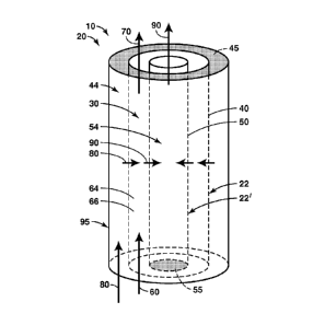
include portions of body 20 that do not include perforations 42 and/or 52, as
well as portions
of body 20 that are coated, covered, constructed, and/or otherwise isolated
such that fluid
does not flow therethrough.
[0066] Wear-resistant region 29 may be designed, constructed, and/or
configured to
decrease physical, mechanical, and/or chemical wear associated with the flow
of slurry
stream 60, product slurry stream 70, displacing fluid stream 80, and/or
displaced fluid stream
90 therethrough and/or thereby. This may include wear-resistant regions with a
different
shape, thickness, surface roughness, and/or chemical composition than other
portions of body
20, as well as wear-resistant regions that include a suitable wear-resistant
surface treatment or
coating. It is within the scope of the present disclosure that wear-resistant
region 29 may
include fluid-impervious region 28. However, it is also within the scope of
the present
disclosure that wear-resistant region 29 may include a fluid-permeable region.
[0067] Specialized region 27 may be included at any suitable location
within slurry
separation assembly 10 and/or body 20. As an illustrative, non-exclusive
example, the force
of gravity acting upon slurry stream 60 may increase wear on a bottom surface
of slurry
conduit 30 due to the flow of slurry stream 60 thereby and/or the abrasive
nature of the solid
- 17 -
CA 02835822 2013-11-12
WO 2012/177327 PCT/US2012/036553
particles contained within slurry stream 60. Under these conditions, the
bottom surface of
slurry conduit 30 may include wear-resistant region 29 to increase the
durability of the slurry
separation assembly.
[0068] It is within the scope of the present disclosure that specialized
region 27 may form
a portion of body 20 (such as when specialized region 27 and body 20 form a
monolithic
structure). However, it is also within the scope of the present disclosure
that specialized
region 27 may include a separate structure that is associated with, in fluid
communication
with, and/or operatively attached to body 20. This may include specialized
regions that may
be configured to be permanently, or substantially permanently attached to body
20, as well as
specialized regions that may be configured to be removed, or otherwise
separated from, body
20, such as for repair, replacement, and/or cleaning.
[0069] Fig. 7 is yet another illustrative, non-exclusive example of a
slurry separation
assembly 10 according to the present disclosure. The slurry separation
assembly of Fig. 7
does not include outer housing 95. Instead, component 22 of Fig. 7 includes a
fluid-
impervious region 28 and one or more flow ports 24 that are operatively
attached to
component 22 such that they are in fluid communication with one or more first
perforated
regions 40. Additionally or alternatively, outer housing 95 may be considered
to form a part
of component 22. Thus, flow port(s) 24 may serve to contain, direct, or
otherwise restrict
fluid flow through first perforated region(s) 40.
[0070] In Fig. 7, displacing fluid stream 80 may be supplied to slurry
conduit 30 through
flow port(s) 24 and first perforated region(s) 40, and produced fluid stream
90 may exit the
slurry conduit through second perforated region 50 as shown. Additionally or
alternatively,
the flow of displacing fluid stream 80 and displaced fluid stream 90 may be
reversed. It is
within the scope of the present disclosure that any suitable number of flow
port(s) 24 may be
utilized, that flow port(s) 24 may be in fluid communication with both first
perforated region
40 and second perforated region 50, and/or that the flow port(s) may be
included within body
20 at any suitable location.
[0071] Fig. 8 is yet another illustrative, non-exclusive example of a
slurry separation
assembly 10 according to the present disclosure. In the slurry separation
assembly of Fig. 8,
regions 22 and 22', including first perforated region 40 and second perforated
region 50,
respectively, may be considered to be separate portions of a continuous, or
substantially
continuous, conduit that is contained within outer housing 95. A barrier 26
separates region
22 from region 22' and prevents, occludes, and/or decreases direct fluid
communication
- 18 -
CA 02835822 2013-11-12
WO 2012/177327 PCT/US2012/036553
between regions 22 and 22'. Instead, fluid communication between regions 22
and 22' may
be accomplished by flowing through first perforated region 40, slurry conduit
30, and second
perforated region 50.
[0072] Figs. 9 and 10 provide yet another illustrative, non-exclusive
example of slurry
separation assemblies 10 according to the present disclosure. As discussed in
more detail
herein, body 20, including elements or regions 22 and 22', may include any
suitable form,
including the planar elements or regions 22 and 22' of Figs. 9 and 10. Fluid,
or stream, flow
in Figs. 9 and 10 is substantially similar to that of Figs. 1-6. In the
forward-flow
configuration, displacing fluid stream 80 may be supplied to first conduit 44,
and be injected
through first perforated region 40 and into slurry conduit 30. Similarly,
displaced fluid
stream 90 may be produced from second perforated region 50 and flow into
second conduit
54.
[0073] Figs. 9 and 10 further illustrate that, as discussed in more
detail herein, first
perforated region 40 and/or second perforated region 50 may be included at any
suitable
(relative) location within slurry separation assembly 10 and/or body 20. Thus,
and as shown
in Fig. 9, it is within the scope of the present disclosure that first
perforated region 40 may be
generally opposed to second perforated region 50, such as when first
perforated region 40 is
spaced apart from second perforated region 50 in a direction that is generally
perpendicular to
a flow direction of slurry stream 60 but not in a direction that is generally
parallel to the flow
direction of slurry stream 60.
[0074] Similarly, and as shown in Fig. 10, it is within the scope of the
present disclosure
that first perforated region 40 may be spaced apart from second perforated
region 50 in a
direction that is generally perpendicular to the flow direction of slurry
stream 60 and in a
direction that is generally parallel to the flow direction of slurry stream
60. Figs. 9 and 10
also illustrate that first perforated region 40 and/or second perforated
region 50 may be
discontinuous, such as discontinuous in a direction that is parallel to the
flow direction of
slurry stream 60, that conduit barriers 45, 55 may control and/or direct fluid
flow within
slurry separation assembly 10, and/or that fluid impervious regions 28 may
separate one or
more perforated region(s) associated with slurry separation assembly 10.
[0075] The slurry separation assemblies disclosed herein may be utilized in
any suitable
manner and/or in any suitable system, apparatus, process, and/or assembly.
Illustrative, non-
exclusive examples of systems, apparatus, processes, and/or assemblies that
may utilize the
slurry separation assemblies disclosed herein are shown in Figs. 11-13. Fig.
11 provides an
- 19 -
CA 02835822 2013-11-12
WO 2012/177327 PCT/US2012/036553
illustrative, non-exclusive example of a dewatering system 98 according to the
present
disclosure, while Figs. 12-13 provide illustrative, non-exclusive examples of
systems
according to the present disclosure for the solvent extraction of mined oil
sands.
[0076] In Fig. 11, a slurry stream 60 is supplied by an optional slurry
stream delivery
system 100 to a slurry separation assembly 10. In addition, a displacing fluid
stream 80 is
supplied to the slurry separation assembly by an optional displacing fluid
delivery system
110. As discussed in more detail herein, slurry separation assembly 10
produces displaced
fluid stream 90 and product slurry stream 70 from the streams supplied
thereto. Displaced
fluid stream 90 may be supplied to an optional displaced fluid receiving
system 120 and/or
product slurry stream 70 may be supplied to an optional product slurry
receiving system 130
for further processing.
[0077] Slurry stream delivery system 100 may include any suitable
structure configured
to supply slurry stream 60 to slurry separation assembly 10. Similarly,
displacing fluid
delivery system 110 may include any suitable structure configured to supply
displacing fluid
stream 80 to slurry separation assembly 10. These may include any suitable
collection of
conduits, pipes, valves, pumps, compressors, storage tanks, mixers, grinders,
system
controllers, transducers, and/or actuators.
[0078] In the illustrative, non-exclusive example of Fig. 11, slurry
stream 60 may include
water 65, as well as mine tailings 67 from a mining operation. Mine tailings
67 may include
small/fine particles 66. Displacing fluid stream 80 may supply any suitable
fluid that may
displace the water from the mine tailings, illustrative, non-exclusive
examples of which
include a gas, air, nitrogen, carbon dioxide, steam, methane, natural gas,
and/or a liquid.
[0079] It is within the scope of the present disclosure that at least an
elevated pressure
portion of dewatering system 98, such as slurry separation assembly 10, slurry
stream
delivery system 100, and/or displacing fluid delivery system 110 may be
configured to be
operated at elevated pressures, including pressures of at least 1 Megapascal
(MPa), at least 2
MPa, at least 3 MPa, at least 5 MPa, at least 10 MPa, at least at least 20
MPa, at least 30
MPa, at least 40 MPa, at least 45 MPa, at least 50 MPa, at least 55 MPa, at
least 60 MPa, at
least 65 MPa, at least 70 MPa, at least 75 MPa, at least 80 MPa, at least 90
MPa, or at least
100 MPa.
[0080] In addition, it is within the scope of the present disclosure that
displacing fluid
stream 80 may include a component that is a gas or vapor at ambient
temperatures and
- 20 -
CA 02835822 2013-11-12
WO 2012/177327 PCT/US2012/036553
pressure but that may exist in a liquid, or supercritical, state at the
elevated pressures present
within the elevated pressure portion of dewatering system 98. Illustrative,
non-exclusive
examples of components that may be liquefied at the elevated pressures present
within the
elevated pressure portion of the dewatering system include propane, butane,
dimethylether,
and/or carbon dioxide. Thus, displacing fluid stream 80 may act as a liquid,
or quasi-liquid,
within slurry separation assembly 10 but may be readily vaporized at ambient
temperatures
and pressures to facilitate separation of the displacing fluid stream from
displaced fluid
stream 90 and/or product slurry stream 70.
[0081] Displaced fluid receiving system 120 may receive displaced fluid
stream 90 from
slurry separation assembly 10 and may process, store, utilize, and/or
otherwise dispose of at
least a portion of the displaced fluid stream. As an illustrative, non-
exclusive example,
displaced fluid stream 90 may include a portion of displacing fluid stream 80,
and the
displaced fluid receiving system may include a separation assembly 140
configured to
separate the components of the displaced fluid stream. As another
illustrative, non-exclusive
example, the displaced fluid receiving system may include a suitable tank,
reservoir, and/or
pond configured to store water 65 removed from the mine tailings stream.
[0082] Product slurry receiving system 130 may receive product slurry
stream 70, which
may include at least a portion of small particles 66 from mine tailings 67, as
well as
displacing fluid 82 from displacing fluid stream 80, and to separate at least
a portion of the
displacing fluid from at least a portion of the small particles to produce a
dried mine tailings
stream 132. This may be accomplished through the use of a separation assembly
140, such as
a depressurization assembly 142, that is configured to decrease a pressure of
the product
slurry stream and vaporize displacing fluid 82 therefrom. Product slurry
receiving system
140 further may include a recycling assembly 150, which may include a
compressor 152, and
may be configured to return at least a portion of the displacing fluid removed
from the
product slurry stream to the displacing fluid delivery system and/or the
slurry separation
assembly as a recycle stream 154.
[0083] Fig. 12 provides a schematic representation of an illustrative,
non-exclusive
example of a solvent extraction system 160 according to the present
disclosure. The solvent
extraction system of Fig. 12 may be utilized to remove solvent from mined oil
sands. In the
system of Fig. 12, an oil sands stream 162, including a hydrocarbon 164 and
solid particles
66, may be supplied to a sizing system 170 that may grind, crush, sort,
segregate, and/or
otherwise ensure a desired, or target, average size of the oil sands and
produce a sized oil
- 21 -
CA 02835822 2013-11-12
WO 2012/177327 PCT/US2012/036553
sands stream 167. As an illustrative, non-exclusive example, the sized oil
sands stream may
include clumps that include a maximum dimension of less than 1 meter, such as
maximum
dimensions of less than 0.75 meters, less than 0.5 meters, less than 0.4
meters, less than 0.3
meters, less than 0.2 meters, or less than 0.1 meters. The sized oil sands
stream may be
supplied to a blend system 175, which may combine the sized oil sands stream
with a heavy
solvent stream 177, including a heavy solvent 178, which may solubilize, or
dissolve, at least
a portion of hydrocarbon 164, such as oil, tar, and/or bitumen, contained
within the oil sands,
to produce an oil sands-solvent mixture stream 179.
[0084] The oil sands-solvent mixture stream may be supplied to an
agitation system 180,
which may further combine the oil sands-solvent mixture to produce a slurry
stream 60. The
slurry stream may be supplied to a slurry separation assembly 10 together with
a displacing
fluid stream 80, such as a light solvent stream 185 including a light solvent
187. The light
solvent stream may displace at least a portion of the slurry liquid, such as
heavy solvent 178,
from slurry stream 60, and the slurry separation assembly may produce a
displaced fluid
stream 90, including the dissolved portion of hydrocarbon 164, heavy solvent
178, and
optionally light solvent 187. Slurry separation assembly 10 also may produce a
product
slurry stream 70, including solid particles 66, light solvent 187, and
optionally heavy solvent
178.
[0085] As used herein, "light solvent" and "heavy solvent" refer to the
relative physical
characteristics of the solvents. As an illustrative, non-exclusive example, a
heavy solvent
may have a higher molecular weight than a light solvent. As another
illustrative, non-
exclusive example, a heavy solvent may have a lower vapor pressure at a given
temperature
than a light solvent. As yet another illustrative, non-exclusive example, at a
given pressure, a
heavy solvent may have a higher bubble point, or boiling point, temperature
than a light
solvent. Likewise, a light solvent may be described as having a lower
molecular weight, a
higher vapor pressure (at a given temperature), and/or a lower bubble or
boiling point (at a
given pressure) than a heavy solvent.
[0086] Displaced fluid stream 90 may be supplied to a separation assembly
140, such as
displaced fluid separation assembly 144, which may separate the components
thereof. This
may include separating the displaced fluid stream into a produced hydrocarbon
stream 190,
including a recovered portion of hydrocarbon 164, and a recovered heavy
solvent stream 191,
including a recovered portion of heavy solvent 178. The recovered heavy
solvent stream may
be supplied to blend system 175 as at least a portion of heavy solvent stream
177.
- 22 -
CA 02835822 2013-11-12
WO 2012/177327 PCT/US2012/036553
[0087] Similarly, product slurry stream 70 may be supplied to a
separation assembly 140,
such as to product slurry separation assembly 146, or an evaporation system
148, which may
separate the components thereof. This may include separating the product
slurry stream into
a dried solid particles stream 192, including solid particles 66, and a
recovered light solvent
stream 194, including light solvent 187. The recovered light solvent stream
may receive
further processing, such as in liquification apparatus 196, before being
returned to slurry
separation assembly 10 as at least a portion of displacing fluid stream 80.
[0088] Fig. 13 provides a less schematic but still illustrative, non-
exclusive example of
another solvent extraction system 160 according to the present disclosure. In
the solvent
extraction system of Fig. 13, oil sands stream 162, including hydrocarbons 164
and small
particles 66, is supplied to sizing system 170 in the form of a grinder 172,
which may
produce a sized oil sands stream 167. The sized oil sands stream may be
combined with a
heavy solvent stream 177, including heavy solvent 178, in blend system 175 to
produce an oil
sands-solvent mixture stream 179. An optional pump 182 may provide a motive
force to oil
sands-solvent mixture stream 170 as it is supplied to agitation system 180,
which may include
static mixers 183 and/or a flow line 184, and may produce slurry stream 60.
[0089] The slurry stream, together with displacing fluid stream 80 in
the form of light
solvent stream 185, including light solvent 187, may be provided to slurry
separation
assembly 10, which may separate these streams into displaced fluid stream 90,
including
hydrocarbon 164 and heavy solvent 178, and optionally including light solvent
187, and
product slurry stream 70, including solid particles 66 and light solvent 187,
and optionally
including heavy solvent 178. As discussed in more detail herein, displaced
fluid stream 90
and/or product slurry stream 70 may optionally receive further processing to
separate,
recycle, and/or recover the components thereof.
[0090] Figs. 12 and 13 provide illustrative, non-exclusive examples of
solvent extraction
systems 160 according to the present disclosure. These solvent extraction
systems may
include any suitable components and receive and/or produce any suitable
streams. As an
illustrative, non-exclusive example, oil sands stream 162 may include any
suitable stream that
may contain hydrocarbon 164 and solid particles 66. The hydrocarbon may
include oil, crude
oil, bitumen, tar, and/or any other suitable hydrocarbon. Similarly, the solid
particles may be
of any suitable size, shape, and/or composition, illustrative, non-exclusive
examples of which
are discussed in more detail herein and may include clay, sand, rock, and/or
soil.
- 23 -
CA 02835822 2013-11-12
WO 2012/177327 PCT/US2012/036553
[0091] Sizing system 170, such as grinder 172, may include any suitable
structure
configured to size, sort, crush, grind, or otherwise produce sized oil sands
stream 167
including a desired, or target, size of solid particles 66. Heavy solvent 178
may include any
suitable heavy solvent that may dissolve, or solubilize, at least a portion of
the hydrocarbons
contained within oil sands stream 162. Illustrative, non-exclusive examples of
heavy solvents
178 according to the present disclosure include diesel fuel, kerosene, fuel
oil, and/or
hydrocarbons, including hydrocarbons with an average molecular weight of at
least 150
grams/mole, at least 175 grams/mole, at least 200 grams/mole, at least 225
grams/mole, at
least 250 grams/mole, at least 275 grams/mole, or at least 300 grams/mole.
Additionally or
alternatively, it is within the scope of the present disclosure that heavy
solvent 178 may
include any suitable solvent with a vapor pressure of less than 20 kilopascal
(kPa) at 20 C,
including heavy solvents with a vapor pressure of less than 15, less than 10,
less than 6.9, less
than 5, less than 1, less than 0.1, less than 0.05, less than 0.01, less than
0.005, less than
0.001, less than 0.0005, or less than 0.0001 kPa at 20 C.
[0092] It is within the scope of the present disclosure that the heavy
solvent may be
combined with the oil sands stream 162 and/or the sized oil sands stream 167
at any suitable
location. As an illustrative, non-exclusive example, blend system 175 may
include a vertical
column as shown schematically in Fig. 13 and heavy solvent stream 178 may be
injected into
the blend system sufficiently low on the vertical column such that a pressure
head of the oil
sands above the injection point is sufficient to decrease, minimize, or even
prevent an escape
of heavy solvent vapor from the top of the vertical column.
[0093] Pump 182 may include any suitable pump configured to supply a
motive force to
oil sands-solvent mixture stream 179 and may be designed to resist wear and/or
damage when
pumping a stream that includes solid particles, such as oil sands-solvent
mixture stream 179.
Additionally or alternatively, it is within the scope of the present
disclosure that pump 182
may not be utilized within solvent extraction system 160 and that the motive
force for oil
sands-solvent mixture stream 179 may be provided by gravitational forces,
hydraulic forces,
and/or another suitable source.
[0094] Agitation system 180 may include any structure configured to
further combine, or
mix, the components of oil sands-solvent mixture stream 179 and may include
active and/or
passive components. Illustrative, non-exclusive examples of active components
according to
the present disclosure include blades, grinders, mills, and/or other apparatus
configured to
shear, combine, or otherwise mix the components of a stream supplied thereto.
Illustrative,
- 24 -
CA 02835822 2013-11-12
WO 2012/177327 PCT/US2012/036553
non-exclusive examples of passive components according to the present
disclosure include
static mixers and/or long flow conduits. As an illustrative, non-exclusive
example, agitation
system 180 may include static mixers 183 contained within a flow line 184.
Static mixers
183 may be configured to impart mixing forces to oil sands-solvent mixture
stream 179
flowing thereby.
[0095] As another illustrative, non-exclusive example, agitation system
180 may include
a long flow line, such as a long pipe, that may provide a significant
residence time with the
agitation system, thereby promoting and/or increasing the mixing within oil
sands-solvent
mixture stream 179. Illustrative, non-exclusive examples of long flow lines
according to the
present disclosure include flow lines of at least 100 meters in length, such
as flow lines of at
least 150 meters, at least 200 meters, at least 250 meters, at least 300
meters, at least 350
meters, at least 400 meters, at least 450 meters, or at least 500 meters in
length. Additionally
or alternatively, flow line 184 may include a characteristic cross-sectional
dimension and a
length of the flow line may be selected such that it is at least 50 times, at
least 100 times, at
least 250 times, at least 500 times, at least 750 times, at least 1000 times,
at least 1250 times,
or at least 1500 times the characteristic cross-sectional dimension.
[0096] Light solvent 187 may include any suitable solvent that may be
selected to
displace at least a portion of heavy solvent 178 from slurry stream 60. This
may include any
of the displacing fluid streams disclosed herein. Additionally or
alternatively, it is within the
scope of the present disclosure that, as discussed in more detail herein, the
light solvent may
include a light solvent that may be readily vaporized and/or liquefied within
solvent
extraction system 160, such as a light solvent that may be liquefied at the
pressures present
within slurry separation assembly 10 but may be readily vaporized for
separation from
product slurry stream 70 at a pressure that is near atmospheric pressure.
Illustrative, non-
exclusive examples of light solvents according to the present disclosure
include hydrocarbons
with a vapor pressure of at least 1 kPa at 20 C, including hydrocarbons with
a vapor pressure
of at least 10 kPa, at least 25 kPa, at least 50 kPa, at least 75 kPa, at
least 100 kPa, at least
150 kPa, at least 200 kPa, at least 250 kPa, at least 300 kPa, at least 400
kPa, or at least 500
kPa at 20 C. Illustrative, non-exclusive examples of light solvents according
to the present
disclosure include propane, butane, carbon dioxide, and/or dimethylether.
[0097] Fig. 14 is a flowchart providing illustrative, non-exclusive
examples of methods
200 of removing fluid from a slurry according to the present disclosure. The
methods further
include flowing the slurry stream through a slurry conduit at 210, and flowing
the slurry
- 25 -
CA 02835822 2013-11-12
WO 2012/177327 PCT/US2012/036553
stream in fluid communication with a first perforated region and a second
perforated region at
215. As indicated in dashed lines at 205, the methods of Fig. 14 may
optionally include
forming a slurry stream. The methods further include injecting a displacing
fluid stream
through the first perforated region and into the slurry conduit at 220,
displacing slurry liquid
from the slurry with the displacing fluid stream at 225, and producing a
displaced fluid
stream from the slurry conduit and through the second perforated region at
230. The methods
optionally may further include one or more of producing a product slurry
stream at 235,
separating components of the product slurry stream at 240, separating
components of the
displaced fluid stream at 245, and/or recycling at least a portion of one or
more of the product
slurry stream and the displaced slurry stream at 250.
[0098] Forming the slurry stream at 205, when utilized in a method 200
according to the
present disclosure, may include the use of any suitable structure and/or
method to form the
slurry stream, including the illustrative, non-exclusive examples disclosed
herein. As an
illustrative, non-exclusive example, it is within the scope of the present
disclosure that
forming the slurry stream may include producing a mine tailings stream from a
mining
operation. As another illustrative, non-exclusive example, forming the slurry
stream may
include combining an oil sands stream with a heavy solvent stream. As yet
another
illustrative, non-exclusive example, forming the slurry stream may include
mixing any
suitable solid particles from any suitable solid particle source, or stream,
with any suitable
liquid from any suitable liquid source, or stream. As another illustrative,
non-exclusive
example, forming the slurry stream may include pumping the slurry stream from
any suitable
slurry source. As yet another illustrative, non-exclusive example, forming the
slurry stream
may include supplying the slurry stream from any suitable slurry stream
delivery system
configured to provide the slurry stream to the slurry conduit.
[0099] Flowing the slurry stream through the slurry conduit at 210 and/or
flowing the
slurry stream in fluid communication with the first perforated region and the
second
perforated region at 215 may include flowing the slurry stream through any
suitable slurry
conduit that is in fluid communication with the first and second perforated
regions,
illustrative, non-exclusive examples of which are discussed in more detail
herein with
reference to previously discussed slurry conduit 30, first perforated region
40, and/or second
perforated region 50. Injecting the displacing fluid stream through the first
perforated region
at 220 may include providing the displacing fluid stream to the first
perforated region at a
pressure that is sufficient to provide for flow of the displacing fluid stream
therethrough. It is
- 26 -
CA 02835822 2013-11-12
WO 2012/177327 PCT/US2012/036553
within the scope of the present disclosure that injecting the displacing fluid
stream through
the first perforated region optionally may include the use of any suitable
displacing fluid
delivery system to provide the displacing fluid stream to the first perforated
region and/or to
inject the displacing fluid stream through the first perforated region and
into the slurry
conduit.
[0100] Displacing slurry liquid from the slurry with the displacing fluid
stream at 225
may include the use of any suitable mechanism to displace from the slurry
stream at least a
portion of the slurry liquid contained within the slurry stream. This may
include pressure-
driven displacement of the slurry liquid from the slurry stream, as well as
displacement that is
driven by thermodynamic interactions, illustrative, non-exclusive examples of
which include
interfacial chemistry, surface energy, and/or surface wetting. It is within
the scope of the
present disclosure that the displacing may include displacing all, or
substantially all, of the
slurry liquid from the slurry with the displacing fluid stream. However, it is
also within the
scope of the present disclosure that the displacing may include displacing a
displaced
fraction, or portion, of the slurry liquid from the slurry stream.
Illustrative, non-exclusive
examples of displaced fractions according to the present disclosure include
displaced
fractions of 10-100 wt% of the slurry liquid, including displaced fractions of
20-95 wt%, 30-
90 wt%, 50-99 wt%, greater than 50 wt%, greater than 60 wt%, greater than 70
wt%, greater
than 75 wt%, greater than 80 wt%, greater than 90 wt%, greater than 95 wt%,
greater than 99
wt%, or greater than 99.5 wt% of the slurry liquid.
[0101] Producing the displaced fluid stream through the second perforated
region at 230
may include flowing the displaced fluid stream through the second perforated
region. It is
within the scope of the present disclosure that this may include maintaining a
pressure of the
displaced fluid stream to be less than a pressure within the slurry conduit.
It is also within the
scope of the present disclosure that producing the displaced fluid stream may
include the use
of any suitable displaced fluid receiving system configured to receive the
displaced fluid
stream from the second perforated region and/or to control the pressure of the
displaced fluid
stream.
[0102] Producing the product slurry stream at 235 may include producing
the product
slurry stream from an exit of the slurry separation assembly, such as the
previously described
product slurry stream 70 and slurry separation assembly 10. It is within the
scope of the
present disclosure that producing the product slurry stream may include the
use of any
suitable product slurry receiving system configured to receive the product
slurry stream,
- 27 -
CA 02835822 2013-11-12
WO 2012/177327 PCT/US2012/036553
perform additional processing on the product slurry stream, and/or store the
product slurry
stream.
[0103] Separating the components of the product slurry stream at 240
and/or separating
the components of the displaced fluid stream at 245 may include the use of any
suitable
structure and/or methods, including those discussed in more detail herein, to
separate the
components thereof, such as to separate the solid particles contained within
the product slurry
stream from the slurry liquid and/or displacing fluid contained therein and/or
to separate the
slurry liquid contained within the displaced fluid stream from the displacing
fluid contained
therein. It is within the scope of the present disclosure that this separation
may include the
use of any suitable separation assembly, illustrative, non-exclusive examples
of which may
include any suitable evaporator, throttle valve, distillation system, phase
separation device,
liquid-vapor separator, solid-liquid separator, and/or solid-vapor separator.
[0104] It is also within the scope of the present disclosure that the
separating may include
separating a substantial portion of the solid particles contained within the
product slurry
stream from the slurry liquid and/or displacing fluid contained therein. As an
illustrative,
non-exclusive example, this may include separating at least 50 wt% of the
slurry liquid
and/or displacing fluid from the solid particles contained within the slurry
stream, including
separating at least 60 wt%, at least 70 wt%, at least 75 wt%, at least 80 wt%,
at least 90 wt%,
at least 95 wt%, at least 99 wt%, or at least 99.5 wt% of the slurry liquid
and/or displacing
fluid from the solid particles contained within the slurry stream.
[0105] Recycling at least a portion of one or more of the product slurry
stream and the
displaced fluid stream at 250 may include the use of any suitable structure
and/or methods to
re-use at least a portion of one or more of the product slurry stream and the
displaced fluid
stream, including the illustrative, non-exclusive examples of recycling
assemblies 150
discussed in more detail herein. As an illustrative, non-exclusive example, it
is within the
scope of the present disclosure that at least a portion of the displacing
fluid that is separated
from the displaced fluid stream at 245 and/or from the product slurry stream
at 245 may be
injected through the first perforated region at 220.
[0106] It is within the scope of the present disclosure that at least
two of the method steps
described in Fig. 14 may be performed simultaneously and/or continuously. This
may
include performing at least three, at least four, at least five, at least six,
at least seven, at least
eight, at least nine, or all 10 of the method steps described in Fig. 14
simultaneously and/or
continuously. As an illustrative, non-exclusive example, the flowing at 210
and 215, the
- 28 -
CA 02835822 2013-11-12
WO 2012/177327 PCT/US2012/036553
injecting at 220, the displacing at 225, and the producing at 230 may be
performed
simultaneously and/or continuously. It is also within the scope of the present
disclosure that,
as discussed in more detail herein, methods 200 also may include reversing the
injecting and
the producing such that the displacing fluid stream may be injected into the
slurry conduit
through the second perforated region and the displaced fluid stream may be
produced from
the slurry conduit through the first perforated region.
[0107] It is further within the scope of the present disclosure that
methods 200 also may
include controlling, or maintaining, one or more pressures within the slurry
separation
assembly. As an illustrative, non-exclusive example, methods 200 may include
at least one
of maintaining a pressure of the displacing fluid stream to be higher than a
pressure of the
slurry stream, maintaining the pressure of the slurry stream to be higher than
a pressure of the
displaced fluid stream, and/or maintaining the pressure of the displacing
fluid stream to be
higher than the pressure of the displaced fluid stream.
[0108] The systems and methods disclosed herein have been described with
reference to
several different embodiments. It is within the scope of the present
disclosure that any
structure and/or function disclosed herein may be utilized in any suitable
manner and with
any of the embodiments disclosed herein. It is also within the scope of the
present disclosure
that the systems disclosed herein may further include any suitable valve,
conduit, pump,
and/or other structure configured to control a flow of fluids and/or streams
therethrough,
including valves, pumps, and/or conduits that may control the supply of the
slurry stream
and/or the displacing fluid stream to the slurry separation assembly, valves,
pipes, and/or
conduits that may control the removal of the product slurry stream and/or the
displaced fluid
stream from the slurry separation assembly, and/or valves, pumps, and/or
conduits that may
provide a mechanism by which the injecting and the producing may be reversed,
as discussed
in more detail herein.
[0109] In the present disclosure, several of the illustrative, non-
exclusive examples have
been discussed and/or presented in the context of flow diagrams, or flow
charts, in which the
methods are shown and described as a series of blocks, or steps. Unless
specifically set forth
in the accompanying description, it is within the scope of the present
disclosure that the order
of the blocks may vary from the illustrated order in the flow diagram,
including with two or
more of the blocks (or steps) occurring in a different order and/or
concurrently.
[0110] As used herein, the term "and/or" placed between a first entity
and a second entity
means one of (1) the first entity, (2) the second entity, and (3) the first
entity and the second
- 29 -
CA 2835822 2017-04-26
entity. Multiple entities listed with "and/or" should be construed in the same
manner, i.e., "one or
more" of the entities so conjoined. Other entities may optionally be present
other than the entities
specifically identified by the "and/or" clause, whether related or unrelated
to those entities
specifically identified. Thus, as a non-limiting example, a reference to "A
and/or B," when used
in conjunction with open-ended language such as "comprising" may refer, in one
embodiment, to
A only (optionally including entities other than B); in another embodiment, to
B only (optionally
including entities other than A); in yet another embodiment, to both A and B
(optionally including
other entities). These entities may refer to elements, actions, structures,
steps, operations, values,
and the like.
[0111] As used herein, the phrase "at least one," in reference to a list of
one or more entities
should be understood to mean at least one entity selected from any one or more
of the entity in the
list of entities, but not necessarily including at least one of each and every
entity specifically listed
within the list of entities and not excluding any combinations of entities in
the list of entities. This
definition also allows that entities may optionally be present other than the
entities specifically
identified within the list of entities to which the phrase "at least one"
refers, whether related or
unrelated to those entities specifically identified. Thus, as a non-limiting
example, "at least one of
A and B" (or, equivalently, "at least one of A or B," or, equivalently "at
least one of A and/or B")
may refer, in one embodiment, to at least one, optionally including more than
one, A, with no B
present (and optionally including entities other than B); in another
embodiment, to at least one,
optionally including more than one, B, with no A present (and optionally
including entities other
than A); in yet another embodiment, to at least one, optionally including more
than one, A, and at
least one, optionally including more than one, B (and optionally including
other entities). In other
words, the phrases "at least one," "one or more," and "and/or are open-ended
expressions that are
both conjunctive and disjunctive ill operation. For example, each of thc
expressions "at least one
of A, B and C," "at least one of A, B, or C," "one or more of A, B, and C,"
"one or more of A, B,
or C" and "A, B, and/or C" may mean A alone, B alone, C alone, A and B
together, A and C
together, B and C together, A, B and C together, and optionally any of the
above in combination
with at least one other entity.
[0112] This paragraph intentionally left blank
- 30 -
CA 2835822 2017-04-26
[0113] As used herein the terms "adapted" and "configured" mean that the
element,
component, or other subject matter is designed and/or intended to perform a
given function. Thus,
the use of the terms "adapted" and "configured" should not be construed to
mean that a given
element, component, or other subject matter is simply "capable of" performing
a given function
but that the element, component, and/or other subject matter is specifically
created for the purpose
of performing the function. It is also within the scope of the present
disclosure that elements,
components, and/or other recited subject matter that is recited as being
adapted to perform a
particular function may additionally or alternatively be described as being
configured to perform
that function, and vice versa.
[0114] Illustrative, non-exclusive examples of systems and methods
according to the present
disclosure are presented in the following enumerated paragraphs. It is within
the scope of the
present disclosure that an individual step of a method recited herein,
including in the following
enumerated paragraphs, may additionally or alternatively be referred to as a
"step for" performing
thc recited action.
[0115] A 1 . A method for removing fluid from a slurry, the method
comprising:
flowing the slurry over a plurality of perforated surfaces that includes at
least a first
perforated surface and a second perforated surface, wherein the slurry
comprises a first fluid and
solid particles, and optionally wherein the flowing includes flowing in a flow
direction, and
further optionally wherein the flow direction is generally parallel to at
least one of the first
perforated surface and the second perforated surface;
injecting a second fluid through the first perforated surface, wherein the
first fluid and the
second fluid include different chemical compositions; and
removing a mixture of the first fluid and the second fluid through the second
perforated
surface.
[0116] A2. The method of paragraph Al, wherein at least one of the
perforated
surfaces includes a porous surface, and optionally wherein both of the
perforated surfaces include
porous surfaces.
[0117] A3. The method of any of paragraphs A1-A2, wherein at least
one of the first
perforated surface and the second perforated surface includes perforations,
and
- 31 -
CA 02835822 2013-11-12
WO 2012/177327 PCT/US2012/036553
optionally wherein at least a portion of the perforations is in fluid
communication with a flow
port, and further optionally wherein at least a portion of the perforations is
in fluid
communication with a plurality of flow ports.
[0118] A4. The method of any of paragraphs A1-A3, wherein the
flowing,
injecting, and removing are simultaneous.
[0119] A5. The method of any of paragraphs A1-A4, wherein the second
fluid
includes hydrocarbons, and optionally wherein the second fluid includes at
least 30 wt%
hydrocarbons, further optionally including at least 40 wt%, at least 50 wt%,
at least 60 wt%,
or at least 70 wt% hydrocarbons, and further optionally wherein the
hydrocarbons have an
average molecular weight of 200 grams/mole or less, optionally including an
average
molecular weight of 150 grams/mole or less, 100 grams/mole or less, 60
grams/mole or less,
or 50 grams/mole or less.
[0120] A6. The method of any of paragraphs A1-A5, wherein the second
fluid
includes carbon dioxide, and optionally wherein the second fluid includes at
least 25 wt%
carbon dioxide, and further optionally wherein the second fluid includes at
least 30 wt%, at
least 35 wt%, at least 40 wt%, at least 45 wt%, at least 50 wt%, at least 55
wt%, at least 60
wt%, at least 65 wt%, at least 70 wt%, or at least 75 wt% carbon dioxide.
[0121] A7. The method of any of paragraphs A1-A6, wherein at least
one of the
first fluid and the second fluid includes at least one of a gas phase fluid, a
vapor phase fluid, a
liquid phase fluid, a supercritical fluid, and a dense supercritical fluid,
and optionally wherein
at least one of the first fluid and the second fluid is at least one of a gas
phase fluid, a vapor
phase fluid, a liquid phase fluid, a supercritical fluid, and a dense
supercritical fluid.
[0122] A8. The method of any of paragraphs A1-A7, wherein the first
fluid
includes at least one of water and brine, and optionally wherein the first
fluid is at least one of
water and brine.
[0123] A9. The method of any of paragraphs A1-A8, wherein the
plurality of
perforated surfaces are in fluid communication with a slurry conduit, wherein
the slurry
conduit forms an annular space, and further wherein the flowing includes
flowing the slurry
within the annular space, and optionally wherein the plurality of perforated
surfaces at least
partially define the slurry conduit, and further optionally wherein the
plurality of perforated
surfaces completely define the slurry conduit.
- 32 -
CA 02835822 2013-11-12
WO 2012/177327 PCT/US2012/036553
[0124] A10. The method of any of paragraphs A1-A9, wherein the
injecting and the
removing include flowing at least one of the first fluid and the second fluid
between the first
perforated surface and the second perforated surface.
[0125] A11. The method of any of paragraphs Al -A10, wherein the
method further
includes periodically reversing the injecting and the removing, and optionally
wherein the
periodically reversing includes injecting the second fluid through the second
perforated
surface and removing the mixture of the first fluid and the second fluid
through the first
perforated surface.
[0126] Al2. The method of any of paragraphs Al -Al 1, wherein each of
the solid
particles include a characteristic dimension, and further wherein at least 50
wt% of the solid
particles with a characteristic dimension of less than 44 microns also have a
characteristic
dimension of less than 10 microns.
[0127] A13. The method of any of paragraphs A1-Al2, wherein at least
one of, and
optionally both of, the first perforated surface and the second perforated
surface includes
perforations, and further wherein the perforations are sized to prevent at
least 99.5 wt% of the
solid particles from passing through the at least one of the first perforated
surface and the
second perforated surface, and optionally wherein the perforations are sized
to prevent at
least 99.5 wt% of the solid particles from passing through both the first
perforated surface
and the second perforated surface.
[0128] A14. The method of any of paragraphs A1-A13, the method further
including separating at least a portion of the second fluid from the first
fluid to form a recycle
stream that includes the second fluid, and optionally wherein the method
includes re-using at
least a portion of the recycle stream during the injecting.
[0129] A15. The method of any of paragraphs A1-A14, the method
further
including forming the slurry, wherein forming the slurry includes combining
the first fluid
and the solid particles to form a slurry mixture, and optionally wherein
forming the slurry
further includes agitating the slurry mixture.
[0130] A16. The method of paragraph A15, wherein the agitating
includes flowing
the slurry mixture, and optionally wherein the flowing includes flowing
through a pipe,
optionally wherein the pipe is at least 300 meters in length.
- 33 -
CA 02835822 2013-11-12
WO 2012/177327 PCT/US2012/036553
[0131] A17. The method of any of paragraphs A15-A16, wherein the
agitating
includes flowing the slurry mixture through a static mixer, and optionally
wherein the static
mixer is contained within the pipe.
[0132] A18. The method of any of paragraphs A1-A17, wherein the
method further
includes evaporating at least a portion of the second fluid from the slurry,
optionally
including evaporating at least a substantial portion of the second fluid from
the slurry,
optionally including evaporating at least 50 wt%, at least 60 wt%, at least 70
wt%, at least 75
wt%, at least 80 wt%, at least 90 wt%, at least 95 wt%, at least 99 wt%, or at
least 99.5 wt%
of the second fluid from the slurry, and further optionally including
evaporating all of the
second fluid from the slurry.
[0133] A19. The method of any of paragraphs A1-A18, wherein the
slurry includes
sand, bitumen, and a hydrocarbon solvent, and optionally wherein the
hydrocarbon solvent
includes a molecular weight of less than 171 grams/mole.
[0134] A20. The method of any of paragraphs A1-A19, wherein the
slurry includes
tailing fines from a mining operation and water.
[0135] A21. The method of any of paragraphs Al-A20, wherein at least
one, and
optionally both, of the first perforated surface and the second perforated
surface includes at
least one of a wire mesh, a metal screen, a sintered metal, a porous ceramic,
and a cemented
rock.
[0136] A22. The method of any of paragraphs A1-A21, wherein flowing the
slurry
includes flowing the slurry using at least one of a laminar flow profile and a
turbulent flow
profile.
[0137] Bl. A method for separating components of a slurry, the
method
comprising:
flowing a slurry stream that includes the slurry through a slurry conduit
defined by a
body, wherein the slurry conduit is in fluid communication with a first
perforated region and
a second perforated region, and further wherein the slurry includes a liquid
and a plurality of
solid particles;
injecting a displacing fluid through the first perforated region and into the
slurry
conduit as a displacing fluid stream; and
- 34 -
CA 02835822 2013-11-12
WO 2012/177327 PCT/US2012/036553
producing a displaced fluid stream from the slurry conduit through the second
perforated region, wherein the displaced fluid stream includes at least a
portion of the
displacing fluid and at least a portion of the liquid from the slurry.
[0138] B2. The method of paragraph Bl, wherein the flowing, the
injecting, and
the producing are simultaneous, and optionally wherein the flowing, the
injecting, and the
producing are continuous.
[0139] B3. The method of any of paragraphs B1-B2, wherein the method
further
includes displacing at least a portion of the liquid from the slurry with the
displacing fluid
stream to create a product slurry stream that includes at least a portion of
the injected
displacing fluid and at least a portion of the plurality of solid particles,
and optionally
wherein the product slurry stream includes a lower concentration of the liquid
than the slurry
stream.
[0140] B4. The method of paragraph B3, wherein the method further
includes
evaporating at least a portion of the displacing fluid from the product slurry
stream to
produce a dried slurry stream.
[0141] B5. The method of paragraph B4, wherein the evaporating
includes
evaporating substantially all, and optionally all, of the displacing fluid
from the product
slurry stream.
[0142] B6. Solid particles produced by the method of paragraph B5.
[0143] B7. The method of any of paragraphs B1-B6, wherein the injecting
includes injecting the displacing fluid at an injection pressure that is
greater than a pressure
within the slurry conduit.
[0144] B8. The method of any of paragraphs B1-B7, wherein the
producing
includes producing the displaced fluid stream at a displaced fluid pressure
that is less than a
pressure within the slurry conduit.
[0145] B9. The method of any of paragraphs B1-B8, wherein the method
further
includes at least one of maintaining a pressure of the displacing fluid stream
to be higher than
a pressure of the slurry stream, maintaining the pressure of the slurry stream
to be higher than
a pressure of the displaced fluid stream, and maintaining the pressure of the
displacing fluid
stream to be higher than the pressure of the displaced fluid stream.
- 35 -
CA 02835822 2013-11-12
WO 2012/177327 PCT/US2012/036553
[0146] B10. The method of any of paragraphs B1-B9, wherein the
method further
includes separating the displaced fluid stream into a liquid stream and a
recycle stream,
wherein the liquid stream includes a lower concentration of the displacing
fluid than the
displaced fluid stream, and optionally wherein the recycle stream includes a
higher
concentration of the displacing fluid than the displaced fluid stream.
[0147] B11. The method of paragraph B10, wherein the method
further includes
injecting at least a portion of the recycle stream as at least a portion of
the displacing fluid
stream.
[0148] B12. The method of any of paragraphs B 1-B11, wherein the
method further
includes forming the slurry stream.
[0149] B13. The method of paragraph B12, wherein forming the
slurry stream
includes combining a feedstock solids stream with a feedstock liquid stream to
produce a
slurry mixture from which the slurry stream is formed.
[0150] B14. The method of paragraph B13, wherein the method
further includes
agitating the slurry mixture.
[0151] B15. The method of paragraph B14, wherein the agitating
includes flowing
the slurry mixture, optionally wherein the flowing includes flowing the slurry
mixture
through a pipe, and further optionally wherein the flowing includes flowing
the slurry
mixture through a pipe of at least 100 meters in length, and optionally
wherein the pipe is at
least 150 meters, at least 200 meters, at least 250 meters, at least 300
meters, at least 350
meters, at least 400 meters, at least 450 meters, or at least 500 meters in
length.
[0152] B16. The method of any of paragraphs B14-B15, wherein the
agitating
includes agitating the slurry mixture with a static mixer, and optionally
wherein the static
mixer is contained within the pipe.
[0153] B17. The method of any of paragraphs B1-B16, wherein the first
perforated
region includes a plurality of first perforations, and further wherein the
injecting includes
injecting the displacing fluid stream through at least a portion of the
plurality of first
perforations.
[0154] B18. The method of any of paragraphs B1-B17, wherein the
first perforated
region includes a first porous region including a plurality of first region
pores, and further
- 36 -
CA 02835822 2013-11-12
WO 2012/177327 PCT/US2012/036553
wherein the injecting includes injecting the displacing fluid stream through
at least a portion
of the plurality of first region pores.
[0155] B19. The method of any of paragraphs B1-B18, wherein the
second
perforated region includes a plurality of second perforations, and further
wherein the
producing includes producing the displaced fluid stream through at least a
portion of the
plurality of second perforations.
[0156] B20. The method of any of paragraphs B1-B19, wherein the
second
perforated region includes a second porous region including a plurality of
second region
pores, and further wherein the producing includes producing the displaced
fluid stream
through at least a portion of the plurality of second region pores.
[0157] B21. The method of any of paragraphs B1-B20, wherein at
least one of the
first perforated region and the second perforated region includes at least one
of a wire mesh, a
metal screen, a sintered metal, a porous ceramic, and cemented rock.
[0158] B22. The method of any of paragraphs B1-B21, wherein the
first perforated
region is generally opposed to the second perforated region.
[0159] B23. The method of any of paragraphs B1-B22, wherein the
first perforated
region is spaced apart from the second perforated region in a direction that
is generally
parallel to a slurry stream flow direction, and optionally in a direction that
is generally
perpendicular to the slurry stream flow direction.
[0160] B24. The method of any of paragraphs B1-B23, wherein the first
perforated
region and the second perforated region form a portion of an annular space,
and optionally
wherein the flowing includes flowing the slurry stream within the annular
space, and further
optionally wherein the first perforated region and the second perforated
region define the
annular space.
[0161] B25. The method of any of paragraphs BI-B24, wherein the body
defines at
least a portion of an annular space, and optionally wherein the flowing
includes flowing the
slurry stream within the annular space.
[0162] B26. The method of any of paragraphs B1-B25, wherein at
least one of the
first perforated region and the second perforated region is in fluid
communication with a flow
port.
- 37 -
CA 02835822 2013-11-12
WO 2012/177327 PCT/US2012/036553
[0163] B27. The method of paragraph B26, wherein at least one of
the first
perforated region and the second perforated region is in fluid communication
with a plurality
of flow ports, and further optionally wherein both the first perforated region
and the second
perforated region are in fluid communication with a plurality of flow ports.
[0164] B28. The method of any of paragraphs B1-B27, wherein the method
further
includes reversing the injecting and the producing, wherein the reversing
includes injecting
the displacing fluid stream through the second perforated region and producing
the displaced
fluid stream through the first perforated region.
[0165] B29. The method of paragraph B28, wherein a portion of the
plurality of
solid particles arc contained within the second perforated region as contained
solid particles,
and further wherein the reversing includes removing a fraction of the
contained solid particles
from the second perforated region, and optionally wherein the fraction of the
contained solid
particles includes at least 50 wt% of the contained solid particles,
optionally including at least
60 wt%, at least 70 wt%, at least 80 wt%, or at least 90 wt% of the contained
solid particles.
[0166] B30. The method of any of paragraphs B28-B29, wherein the
reversing
includes at least one of periodically reversing and reversing responsive to
the occurrence of
an event.
[0167] B31. The method of paragraph B30, wherein the event
includes detecting at
least one of a flow rate of the displacing fluid stream that is less than a
threshold magnitude, a
flow rate of the slurry stream that is less than a threshold magnitude, a flow
rate of the
displaced fluid stream that is less than a threshold magnitude, a pressure
differential between
the displacing fluid stream and the slurry stream that is greater than a
threshold magnitude, a
pressure differential between the slurry stream and the displaced fluid stream
that is greater
than a threshold magnitude, and a pressure differential between the displacing
fluid stream
and the displaced fluid stream that is greater than a threshold magnitude.
[0168] B32. The method of any of paragraphs B1-B31, wherein the
slurry includes
sand, bitumen, and a hydrocarbon solvent, and optionally wherein the
hydrocarbon solvent
includes a molecular weight of less than 200 grams/mole, optionally including
a molecular
weight of less than 190 grams/mole, less than 180 grams/mole, less than 171
grams/mole,
less than 170 grams/mole, less than 160 grams/mole, or less than 150
grams/mole.
- 38 -
CA 02835822 2013-11-12
WO 2012/177327 PCT/US2012/036553
[0169] B33. The method of paragraph B32, wherein at least a
portion of the
bitumen is dissolved within the hydrocarbon solvent, and further wherein the
liquid includes
the portion of the bitumen and the hydrocarbon solvent.
[0170] B34. The method of any of paragraphs B1-B33, wherein the
slurry includes
water and mine tailing fines from a mining operation.
[0171] B35. The method of any of paragraphs B1-B34, wherein the
liquid includes
at least one of water and brine, and optionally wherein the liquid is at least
one of water and
brine.
[0172] B36. The method of any of paragraphs B1-B35, wherein the
displacing fluid
includes at least 25 wt% hydrocarbons, optionally including at least 30 wt%,
at least 40 wt%,
at least 50 wt%, at least 60 wt%, at least 70 wt%, or at least 75 wt%
hydrocarbons, and
further optionally wherein the hydrocarbons include an average molecular
weight of less than
or equal to 250 grams/mole, optionally including an average molecular weight
of less than or
equal to 225 grams/mole, less than or equal to 200 grams/mole, less than or
equal to 175
grams/mole, less than or equal to 150 grams/mole, less than or equal to 125
grams/mole, less
than or equal to 100 grams/mole, less than or equal to 90 grams/mole, less
than or equal to 80
grams/mole, less than or equal to 70 grams/mole, less than or equal to 60
grams/mole, less
than or equal to 50 grams/mole, less than or equal to 40 grams/mole, or less
than or equal to
30 grams/mole.
[0173] B37. The method of any of paragraphs B1-B36, wherein the
displacing fluid
includes at least 25 wt% carbon dioxide, optionally including at least 30 wt%,
at least 35
wt%, at least 40 wt%, at least 45 wt%, at least 50 wt%, at least 55 wt%, at
least 60 wt%, at
least 65 wt%, at least 70 wt%, or at least 75 wt% carbon dioxide.
[0174] B38. The method of any of paragraphs B1-B37, wherein the
displacing fluid
includes at least one of a gas phase fluid, a vapor phase fluid, a liquid
phase fluid, a
supercritical fluid, and a dense supercritical fluid, and optionally wherein
the displacing fluid
is at least one of a gas phase fluid, a vapor phase fluid, a liquid phase
fluid, a supercritical
fluid, and a dense supercritical fluid.
[0175] B39. The method of any of paragraphs B1-B38, wherein the
injecting and
the producing include flowing at least a portion of at least one of the liquid
and the displacing
fluid between the first perforated region and the second perforated region.
- 39 -
CA 02835822 2013-11-12
WO 2012/177327 PCT/US2012/036553
[0176] B40. The method of any of paragraphs B1-B39, wherein at least
one of the
first perforated region and the second perforated region is sized to prevent
at least 90 wt% of
the plurality of solid particles from passing therethrough, and optionally
wherein at least one
of the first perforated region and the second perforated region is sized to
prevent at least 92
wt%, 94 wt%, 96 wt%, 98 wt%, 99 wt%, 99.5 wt%, or 99.9 wt% of the plurality of
solid
particles from passing therethrough.
[0177] B41. The method of any of paragraphs B1-B40, wherein each of
the
plurality of solid particles includes a characteristic dimension, and further
wherein at least 30
wt% of the plurality of solid particles with a characteristic dimension of
less than 44 microns
also have a characteristic dimension of less than 10 microns, and optionally
wherein at least
40 wt%, at least 50 wt%, at least 60 wt%, or at least 70 wt% of the plurality
of solid particles
with a characteristic dimension of less than 44 microns also have a
characteristic dimension
of less than 10 microns.
[0178] B42. The method of any of paragraphs B1-B41, wherein the
flowing
includes flowing the slurry under at least one of a laminar flow profile and a
turbulent flow
profile.
[0179] Cl. An apparatus for removing at least a portion of a first
fluid from a
slurry comprising the first fluid and solid particles, the apparatus
comprising:
a first perforated surface;
a second perforated surface;
a slurry conduit in fluid communication with the first perforated surface and
the
second perforated surface;
a means for injecting a second fluid through the first perforated surface; and
a means for removing a mixture of the first fluid and the second fluid through
the
second perforated surface.
[0180] C2. The apparatus of paragraph CI, wherein the apparatus
further includes
a means for injecting the second fluid through the second perforated surface.
[0181] C3. The apparatus of any of paragraphs C1-C2, wherein the
apparatus
further includes a means for removing the mixture of the first fluid and the
second fluid
through the first perforated surface.
- 40 -
CA 02835822 2013-11-12
WO 2012/177327 PCT/US2012/036553
[0182] C4. The apparatus of any of paragraphs C1-C3, wherein the
slurry conduit
forms an annular space through which the slurry flows.
[0183] C5. The apparatus of any of paragraphs C1-C4, wherein the
apparatus
further includes an outer housing, and further wherein the first perforated
surface, the second
perforated surface, and the slurry conduit are contained within the outer
housing.
[0184] C6. The apparatus of paragraph C5, wherein the first
perforated surface,
the second perforated surface, and the outer housing form a pipe-in-pipe-in-
pipe arrangement.
[0185] C7. The apparatus of any of paragraphs C1-C6, wherein the
apparatus
further includes a separation system for separating at least a portion of the
second fluid from
the mixture of the first fluid and the second fluid.
[0186] C8. The apparatus of paragraph C7, wherein the separation
system includes
at least one of a distillation system, a throttle valve, and a liquid-vapor
separation assembly.
[0187] C9. The apparatus of any of paragraphs C7-C8, wherein the
apparatus
further includes a recycle system for reusing the second fluid separated from
the mixture.
[0188] C10. The apparatus of any of paragraphs C1-C9, wherein at least
one of the
first perforated surface and the second perforated surface includes at least
one of a wire mesh,
a metal screen, a sintered metal, a porous ceramic, or a cemented rock.
[0189] C11. The apparatus of any of paragraphs C1-C10, wherein at
least one of the
first perforated surface and the second perforated surface is configured to be
removed from
the apparatus.
[0190] C12. The apparatus of any of paragraphs C1-C11, wherein at
least one of the
first perforated surface and the second perforated surface does not extend to
a bottom surface
of the slurry conduit.
[0191] C13. The apparatus of any of paragraphs C1-C12, wherein at
least one of the
first perforated surface and the second perforated surface is configured to
prevent at least 90
wt% of the plurality of solid particles from passing therethrough, and
optionally wherein at
least one of the first perforated surface and the second perforated surface is
configured to
prevent at least 92 wt%, 94 wt%, 96 wt%, 98 wt%, 99 wt%, 99.5 wt%, or 99.9 wt%
of the
plurality of solid particles from passing therethrough.
- 41 -
CA 02835822 2013-11-12
WO 2012/177327 PCT/US2012/036553
[0192] C14. The apparatus of paragraph C13, wherein at least 50 wt%
of any of the
solid particles in the slurry that are less than 1 micron in diameter may pass
through at least
one of the first perforated surface and the second perforated surface.
[0193] Dl. An apparatus for removing fluid from a slurry, the
apparatus
comprising:
a body defining a slurry conduit, wherein the slurry conduit is in fluid
communication
with a first perforated region and a second perforated region;
a slurry stream delivery system configured to provide a slurry stream
including the
slurry to the slurry conduit, wherein the slurry includes a liquid and a
plurality of solid
particles;
a displacing fluid delivery system configured to inject a displacing fluid
through the
first perforated region and into the slurry conduit as a displacing fluid
stream; and
a displaced fluid receiving system configured to receive a displaced fluid
stream from
the slurry conduit through the second perforated region, wherein the displaced
fluid stream
includes at least a portion of the displacing fluid and at least a portion of
the liquid from the
slurry.
[0194] D2. The apparatus of paragraph D1, wherein the apparatus is
configured to
supply the slurry stream, inject the displacing fluid stream, and receive the
displaced fluid
stream simultaneously, and optionally wherein the apparatus is configured to
supply the
slurry stream, inject the displacing fluid stream, and receive the displaced
fluid stream
continuously.
[0195] D3. The apparatus of any of paragraphs D1-D2, wherein the
apparatus
further includes a product slurry receiving system configured to receive a
product slurry
stream from the slurry conduit, wherein the product slurry stream includes at
least a portion
of the displacing fluid and at least a portion of the plurality of solid
particles, and optionally
wherein the product slurry stream includes a lower concentration of the liquid
than the slurry
stream.
[0196] D4. The apparatus of paragraph D3, wherein the apparatus
further includes
an evaporator configured to evaporate at least a portion of the displacing
fluid from the
product slurry stream to produce a dried slurry stream, and optionally wherein
the evaporator
is configured to evaporate all of the displacing fluid from the product slurry
stream.
- 42 -
CA 02835822 2013-11-12
WO 2012/177327 PCT/US2012/036553
[0197] D5. The apparatus of any of paragraphs Dl-D4, wherein the
apparatus
further includes a separation assembly configured to separate the displaced
fluid stream into a
liquid stream and a recycle stream, wherein the liquid stream includes a lower
concentration
of the displacing fluid than the displaced fluid stream, and further wherein
the recycle stream
includes a higher concentration of the displacing fluid than the displaced
fluid stream, and
optionally wherein the separation assembly includes at least one of a
distillation system, a
throttle valve, and a liquid-vapor separation assembly.
[0198] D6. The apparatus of paragraph D5, wherein the apparatus
further includes
a recycle system configured to supply at least a portion of the recycle stream
to the displacing
fluid delivery system for injection into the slurry conduit.
[0199] D7. The apparatus of any of paragraphs D1-D6, wherein the
slurry stream
delivery system includes a mixing assembly configured to receive a feedstock
solids stream
and a feedstock liquid stream and to produce the slurry stream.
[0200] D8. The apparatus of paragraph D7, wherein the mixing
assembly includes
an agitator configured to mix the feedstock solids stream and the feedstock
liquid stream.
[0201] D9. The apparatus of paragraph D8, wherein the agitator
includes a pipe,
and further wherein the pipe is at least 100 meters in length, and optionally
wherein the pipe
is at least 150 meters, at least 200 meters, at least 250 meters, at least 300
meters, at least 350
meters, at least 400 meters, at least 450 meters, or at least 500 meters in
length.
[0202] D10. The apparatus of any of paragraphs D8-D9, wherein the
agitator
includes a static mixer, and optionally wherein the static mixer is contained
within the pipe.
[0203] D11. The apparatus of any of paragraphs D1-D10, wherein the
first
perforated region includes a plurality of first perforations, and further
wherein the displacing
fluid delivery system is configured to inject the displacing fluid through at
least a portion of
the plurality of first perforations.
[0204] D12. The apparatus of any of paragraphs D1-D11, wherein the
first
perforated region includes a first porous region that includes a plurality of
first region pores,
and further wherein the displacing fluid delivery system is configured to
inject the displacing
fluid through at least a portion of the plurality of first region pores.
[0205] D13. The apparatus of any of paragraphs D1-D12, wherein the
second
perforated region includes a plurality of second perforations, and further
wherein the
- 43 -
CA 02835822 2013-11-12
WO 2012/177327 PCT/US2012/036553
displaced fluid receiving system is configured to receive the displaced fluid
stream through at
least a portion of the plurality of second perforations.
[0206] D14. The apparatus of any of paragraphs D1-D13, wherein the
second
perforated region includes a second porous region that includes a plurality of
second region
pores, and further wherein the displaced fluid receiving system is configured
to receive the
displaced fluid stream through at least a portion of the plurality of second
region pores.
[0207] D15. The apparatus of any of paragraphs D1-D14, wherein at
least one of
the first perforated region and the second perforated region includes at least
one of a wire
mesh, a metal screen, a sintered metal, a porous ceramic, and cemented rock.
[0208] D16. The apparatus of any of paragraphs D1-D15, wherein at least
one of
the first perforated region and the second perforated region includes a
removable portion
configured to be removed from the apparatus.
[0209] D17. The apparatus of any of paragraphs D1-D16, wherein the
first
perforated region is generally opposed to the second perforated region.
[0210] D18. The apparatus of any of paragraphs D1-D17, wherein the first
perforated region is spaced apart from the second perforated region in a
direction that is
generally parallel to a slurry stream flow direction, and optionally in a
direction that is
generally perpendicular to the slurry stream flow direction.
[0211] D19. The apparatus of any of paragraphs D1-D18, wherein the
first
perforated region and the second perforated region form a portion of an
annular space, and
optionally wherein the slurry stream delivery system is configured to supply
the slurry stream
to the annular space.
[0212] D20. The apparatus of any of paragraphs D1-D18, wherein the
body defines
at least a portion of an annular space, and optionally wherein the slurry
stream delivery
system is configured to supply the slurry stream to the annular space.
[0213] D21. The apparatus of any of paragraphs D19-D20, wherein
the apparatus
further includes an outer housing that surrounds at least a portion of the
body, optionally
wherein the outer housing, and the body form a pipe-in-pipe arrangement.
[0214] D22. The apparatus of paragraph D21, wherein the body is a
first body that
includes the first perforated region, wherein the apparatus further includes a
second body that
- 44 -
CA 02835822 2013-11-12
WO 2012/177327 PCT/US2012/036553
includes the second perforated region, and further wherein, the outer housing,
the first body,
and the second body form a pipe-in-pipe-in-pipe arrangement.
[0215] D23. The apparatus of any of paragraphs D1-D22, wherein the
body
includes a fluid impervious region.
[0216] D24. The apparatus of paragraph D23, wherein the fluid impervious
region
forms at least a portion of a bottom surface of the body.
[0217] D25. The apparatus of any of paragraphs D23-D24, wherein
the fluid
impervious region is configured to be selectively removed from the apparatus,
and optionally
wherein the fluid impervious region is configured to be replaced.
[0218] D26. The apparatus of any of paragraphs D23-D25, wherein the
fluid
impervious region is configured to form a wear-resistant surface.
[0219] D27. The apparatus of any of paragraphs D23-D26, wherein
the fluid
impervious region is continuous in a direction that is generally parallel to a
slurry stream flow
direction.
[0220] D28. The apparatus of any of paragraphs D23-D27, wherein the
fluid
impervious region is discontinuous in a direction that is generally parallel
to a slurry stream
flow direction.
[0221] D29. The apparatus of any of paragraphs D1-D28, wherein at
least one of
the first perforated region and the second perforated region is in fluid
communication with a
flow port, and optionally wherein at least one of the first perforated region
and the second
perforated region is in fluid communication with a plurality of flow ports,
and further
optionally wherein both the first perforated region and the second perforated
region are in
fluid communication with a plurality of flow ports.
[0222] D30. The apparatus of any of paragraphs D1-D29, wherein the
displacing
fluid delivery system is configured to periodically inject the displacing
fluid through the
second perforated region and into the slurry stream as the displacing fluid
stream, and further
wherein the displaced fluid receiving system is configured to periodically
receive the
displaced fluid stream from the first perforated region.
[0223] D31. The apparatus of any of paragraphs Dl-D30, wherein the
slurry
includes sand, bitumen, and a hydrocarbon solvent, and optionally wherein the
hydrocarbon
solvent includes a molecular weight of less than 200 grams/mole, optionally
including a
- 45 -
CA 02835822 2013-11-12
WO 2012/177327 PCT/US2012/036553
molecular weight of less than 190 grams/mole, less than 180 grams/mole, less
than 171
grams/mole, less than 170 grams/mole, less than 160 grams/mole, or less than
150
grams/mole.
[0224] D32. The apparatus of paragraph D31, wherein at least a
portion of the
bitumen is dissolved within the hydrocarbon solvent, and further wherein the
liquid includes
the portion of the bitumen and the hydrocarbon solvent.
[0225] D33. The apparatus of any of paragraphs D1-D32, wherein the
slurry
includes water and mine tailing fines from a mining operation.
[0226] D34. The apparatus of any of paragraphs D1-D33, wherein the
liquid
includes at least one of water and brine, and optionally wherein the liquid is
at least one of
water and brine.
[0227] D35. The apparatus of any of paragraphs D1-D34, wherein the
displacing
fluid includes at least 25 wt% hydrocarbons, optionally including at least 30
wt%, at least 40
wt%, at least 50 wt%, at least 60 wt%, at least 75 wt%, or at least 75 wt%
hydrocarbons, and
further optionally wherein the hydrocarbons include an average molecular
weight less than or
equal to 250 grams/mole, optionally including an average molecular weight of
less than or
equal to 225 grams/mole, less than or equal to 200 grams/mole, less than or
equal to 175
grams/mole, less than or equal to 150 grams/mole, less than or equal to 125
grams/mole, less
than or equal to 100 grams/mole, less than or equal to 90 grams/mole, less
than or equal to 80
grams/mole, less than or equal to 70 grams/mole, less than or equal to 60
grams/mole, less
than or equal to 50 grams/mole, less than or equal to 40 grams/mole, or less
than or equal to
grams/mole.
[0228] D36. The apparatus of any of paragraphs DI-D35, wherein the
displacing
fluid includes at least 25 wt% carbon dioxide, optionally including at least
30 wt%, at least 35
25 wt%, at least 40 wt%, at least 45 wt%, at least 50 wt%, at least 55 wt%,
at least 60 wt%, at
least 65 wt%, at least 70 wt%, or at least 75 wt% carbon dioxide.
[0229] D37. The apparatus of any of paragraphs D1-D36, wherein the
displacing
fluid includes at least one of a gas phase fluid, a vapor phase fluid, a
liquid phase fluid, a
supercritical fluid, and a dense supercritical fluid, and optionally wherein
the displacing fluid
30 is at least one of a gas phase fluid, a vapor phase fluid, a liquid
phase fluid, a supercritical
fluid, and a dense supercritical fluid.
- 46 -
CA 02835822 2013-11-12
WO 2012/177327 PCT/US2012/036553
[0230] D38. The apparatus of any of paragraphs D1-D37, wherein at
least one of
the first perforated region and the second perforated region is sized to
prevent at least 90 wt%
of the plurality of solid particles from passing therethrough, and optionally
wherein at least
one of the first perforated region and the second perforated region is sized
to prevent at least
92 wt%, 94 wt%, 96 wt%, 98 wt%, 99 wt%, 99.5 wt%, or 99.9 wt% of the plurality
of solid
particles from passing therethrough.
[0231] D39. The apparatus of paragraph D38, wherein at least one of
the first
perforated region and the second perforated region is sized to permit at least
30 wt% of a
portion of the solid particles that are less than 1 micron in diameter to pass
therethrough, and
optionally wherein at least one of the first perforated region and the second
perforated region
is sized to permit at least 40 wt%, at least 50 wt%, at least 60 wt%, or at
least 70 wt% of the
portion of the solid particles that are less than 1 micron in diameter to pass
therethrough.
[0232] D40. The apparatus of any of paragraphs D1-D39, wherein each
of the
plurality of solid particles includes a characteristic dimension, and further
wherein at least 30
wt% of the solid particles with a characteristic dimension of less than 44
microns also have a
characteristic dimension of less than 10 microns, and optionally wherein at
least 40 wt%, at
least 50 wt%, at least 60 wt%, or at least 70 wt% of the solid particles with
a characteristic
dimension of less than 44 microns also have a characteristic dimension of less
than 10
microns.
[0233] D41. The apparatus of any of paragraphs D1-D40, wherein the
slurry stream
delivery system is configured to deliver the slurry stream at a delivery flow
rate, and further
wherein, at the delivery flow rate, the slurry stream includes at least one of
a laminar flow
profile and a turbulent flow profile when in fluid communication with the
slurry conduit.
[0234] El. The use of the methods of any of paragraphs Al-B42 with
any of the
apparatus of any of paragraphs C1-D40.
[0235] E2. The use of any of the apparatus of any of paragraphs C1-
D40 with any
of the methods of any of paragraphs A1-B42.
[0236] E3. The use of any of the methods of any of paragraphs A1-B42
and/or any
of the apparatus of any of paragraphs C1-D40 to produce hydrocarbons.
[0237] E4. The use of any of the methods of any of paragraphs A1-B43
and/or any
of the apparatus of any of paragraphs C1-D40 to dewater mine tailings.
- 47 -
CA 02835822 2013-11-12
WO 2012/177327 PCT/US2012/036553
[0238] E5. Dewatered mine tailings produced by the use of paragraph
E4.
[0239] E6. The use of any of the methods of any of paragraphs A1-B42
and/or any
of the apparatus of any of paragraphs C1-D40 to separate the components of a
two-phase
mixture.
[0240] E7. The use of any of the methods of any of paragraphs A1-B42
and/or any
of the apparatus of any of paragraphs C1-D40 as part of an oil production
operation.
[0241] E8. Oil produced by the use of paragraph E7.
- 48 -
CA 02835822 2013-11-12
WO 2012/177327 PCT/US2012/036553
Industrial Applicability
The systems and methods disclosed herein are applicable to the oil and gas
industry.
It is believed that the disclosure set forth above encompasses multiple
distinct
inventions with independent utility. While each of these inventions has been
disclosed in its
preferred form, the specific embodiments thereof as disclosed and illustrated
herein are not to
be considered in a limiting sense as numerous variations are possible. The
subject matter of
the inventions includes all novel and non-obvious combinations and
subcombinations of the
various elements, features, functions and/or properties disclosed herein.
Similarly, where the
claims recite "a" or "a first" element or the equivalent thereof, such claims
should be
understood to include incorporation of one or more such elements, neither
requiring nor
excluding two or more such elements.
It is believed that the following claims particularly point out certain
combinations and
subcombinations that are directed to one of the disclosed inventions and are
novel and non-
obvious. Inventions embodied in other combinations and subcombinations of
features,
functions, elements and/or properties may be claimed through amendment of the
present
claims or presentation of new claims in this or a related application. Such
amended or new
claims, whether they are directed to a different invention or directed to the
same invention,
whether different, broader, narrower, or equal in scope to the original
claims, are also
regarded as included within the subject matter of the inventions of the
present disclosure.
- 49 -