Note: Descriptions are shown in the official language in which they were submitted.
CA 02836041 2013-12-09
WO 2007/037975
PCT/ES2006/035450
SYSTEM AND METHOD OF ADMINISTERING
A PHARMACEUTICAL GAS TO A PATIENT
Background
The present invention relates to a method and system for Adminigtering a
pharmaceutical gas to a patient and, more particularly, to a method and system
for
introducing carbon monoxide CO or nitric oxide NO to a patient in a
predetermined
qumtity.
Background of the Invention
The normal or conventional way of giving a pharmaceutical drug to a patient is
to prescribe the dose based on the quantity of drug (usually in weight) per
unit weight
of the patient (e.g. in,s,,,/Kg) with the dose being specified to be delivered
over a period
of time or being repeated at specified intervals of time. This allows the user
to control
the quantity of drag and ensures the quantity of drug being delivered is in
proportion
to the patient's size. This is to reduce the patient to patient variability in
response to
the drug due to the size of the patient i.e. a 7Kg baby will not get the same
quantity of
drug as a 80 Kg adult
In recent times there have been a number of gases which have been shown to
have pharmaceutical action in humans and animals. Examples include Nitric
Oxide
(NO) Zapol et al US 5,485,827 and more recently Carbon Monoxide (CO) Otterbein
et al (U.S. Published Patent Application No. 2003/0219496). In the Otterbein
patent
application, CO is described as having a pharmacological action in a number of
medical conditions including ilems and vascular disease.
In these cases, the carbon monoxide gas needs to be delivered to the patients
alveoli where it can move across the alveolar membrane and into the blood
stream
where its action can take effect The current dosing used in these cases is for
the
patient to breath at a specified concentration of CO in ppm for a specified
period of
1
CA 02836041 2013-12-09
WO 2007/037975
PCT/US2006/035450
time. Accurate dosing of CO for these treatments is important as CO reacts
with the.
hemoglobin in the blood to form carboxyhemoglobin which infts-ng the
hemoglobin is
no longer able to carry oxygen to the tissues of the body. If too much CO is
given, the
patient may exhibit the toxic effects of CO for which it is usually blown,
There is a tight window for CO delivery between the therapeutic level and the
level that causes carboxyhemaglobin above safe levels. lip until now CO has
been
delivered as a constant concentration in the gas breathed by the
patient/animal for a
specified period of time. For exsmple in reference 3 of the Otterbein
publication,
(Example 2 pg 13) the therapeutic dose delivered to mice for the treatment of
ileus
was 250 ppm of CO for 1 hour.
However, this method of dosing CO can be associated with large variability in
the actual dose being delivered to the animal/humans alveoli. This variability
is
because the quantity of CO being delivered to the animal/patient is dependent
on a
number of variables including, but not limited to, the patients tidal volume,
respiratory
rate, diffusion rate across the alveolar and ventilation/perfusion (V/Q)
matching.
The amount of CO delivered into a patient's alveoli can be determined by the
irIP-al gas law as shown in the following equation:
N = P . V / (Rn (1)
Where:
N is the number of moles of the gas (mole)
P is the absolute pressure of the gas (joule/m3)
V is the volume of the particillsr gas (m3)
Ru is the universal gas constant, 8.315 (joule/(gmole. K)
T is the absolute temperature ( K)
If we assume atmospheric pressure (101,315 joule/m3) and 20 C (293 K) as
the temperature and we express the volume in mL ( x10-6 m3 ) then equation (I)
reduces to:
2
=
CA 02836041 2013-12-09
- WO 2007/037975
PCT/US2006/035450
N = 4.16x10⁻⁵. V (moles) (2)
Equation (2) can be used to calculate the number of moles of gas delivered to
a
patient's alveolar volume over a period of time when given a specified
concentration
by using the following equation:
Nco = RR . t . ccx, .10 -6=4.16 x10⁻⁵. V.. (3)
Where;
is the concentration of CO (PPIn)
Va is the alveolar volume (mL)
RR is the respiratory rate in (BPM)
t is the time in minutes (mins)
For example if the CO dose for ileus in humans was 250 ppm of CO for one
hour (60 minutes), the alveolar volume is 300 mL and the patients respiratory
rate is
12 breaths per minute (bpm.) then the amount of CO gas in moles delivered to
the
patients alveoli over that period would be:
Nco = 12. 60 . 250 . 10 -6 4.16 x10⁵. 300 = 2.25 x 10⁻³ (moles)
This can be converted into the mass of drug delivered (Mco) using the gram
molecular weight of CO which is 2.8 as shown in the following equation:
1VIco = Nco . 28 = 63 x 10-3 (g) = 63 (mg) (4)
However, although this works for a given set of assumptions, a spontaneous
patient's respiratory rate can vary widely from perhaps 8 to 20 breaths per
minute
depending on circumstances and the patient's alveolar volume per breath can
also vary
significantly from say 200 to 400 mL depending on the metabolic need. These
variables can have a dramatic effect on the amount of gaseous drug being
delivered to
the patient over the same period of time. For instance if the patients
respiratory rate
was 8 bpm and the alveolar volume was 200 mL, the CO dose delivered to the
patients alveoli would have been 27.8 (mg). T ikewise if the patients
respiratory rafr
was 20 bpm and the alveolar volnme was 400 mL, then the dose delivered to the
3
=
CA 02836041 2013-12-09
WO 2007/037975
PCT/US2006/035450
patients alveoli would have been 139.2 (mg) thus representing a five fold
difference in
the amount of drag being delivered..
This means, in the example of CO, the quantity of gaseous drug a patient gets
as measured in grams could vary substantially depending on the patient's
ventilation
pattern. For a dose based on constant concentration and time, the effect of
these
variables could mean that an individual patient could get significantly higher
or lower
doses of CO in gams and this could result in either high unsafe levels of
carboxyhemaglobin or doses too low to be effective, Although not all the
gaseous
drug delivered to the alveoli will be taken up by the bodies bloodstream (due
to
variables such as cardiac output and the diffusion coefficient of the gas)
controlling
the amount delivered to the alveoli takes away a major source of variability.
In addition, there is a need to administer NO to a patient in a predetermined
quantity as described in "Cell-free hemoglobin limits nitric oxide
bioavailabllity in
sickle-cell disease", Natare Medicine, Volume 8, Number 12, December 2002,
pages
1383 et seq. This paper describes the use of inhaled NO to react with cell
free
hemoglobin to form plasma methemaglobin and so reduce the ability of the cell
free
hemoglobin in the plasma to consume endogenously produced NO (fig. 5, page
1386).
The quantity of NO delivered to the patient blood needs to be equivalent to
the
amount of cell free hemoglobin that is in the patients plasma.. The amount of
NO
delivered to a sample of sickle cell patients was 80ppm of NO for 1.5 hours.
However, there was variability in the amount of methemoglobin produced in
individual patients as shown by the error bars on Fig. 4b. So, in a similar
way to the
CO example, a known quantity of NO needs to be delivered to a patient to
provide the
desired therapeutic effect and again it is important to remove any variability
of
delivery because of differences in the individual patient's respiratory
pattern.
Accordingly, it would be advantageous to have a system and method of
introducing pharmaceutical gases (such as carbon monoxide and nitric oxide)
that
allows for the precise control of a blown quantity of the pharmaceutical gas
to be
4
CA 02836041 2013-12-09
WO 2007/037975
PCT/US2006/035450
delivered to the patients alveoli and which is not subject to change based on
the
patients respiratory patterns.
Summary of the Invention
Accordingly, the present invention relates to a system and method for
administering a pharmaceutical gas, such as carbon monoxide and nitric oxide,
that
allows a clinician to determine and control the desired quantity of the gas to
be delivered
to the patient. The method determines the desired quantity of the
pharmaceutical gas to
be administered to the patient and then administers the desired quantity of
the
pharmaceutical gas irrespective of the patients respiratory patterns. If the
prescription is
specified as a total quantity of drug, then the method terminates the
administration of the
pharmaceutical gas when the desired total qnantity has been administered to
the patient.
Thus, by the method of the present invention, the amount of the pharmaceutical
gas is delivered to the patient as a known desired quantity and that known
desired
quantity can be expressed in various units of measurement, such as, but not
limited to,
the weight of drug in micrograms ( g), milligrams (mg), grams (g) etc., the
moles of
drug in nanomoles (nM), micromoles (p.M), __ (mM) moles (M) etc, or the
volume of drag, at a known concentration or partial pressure, in microliters
(aL),
milliliters (mL), liters (L) etc. The desired quantity of the pharmaceutical
gas can also
be expressed as an amount per unit of time for a period of time such as
mg/hour for 2
hours.
The invention also includes a system for administering a pharmaceutical gas,
such as carbon monoxide or nitric oxide, and the system includes an inlet
means that can
be connected to the source of the pharmaceutical gas and deliver the gas to a
patient by
means of a patient device. That patient device can be any device that actually
introduces
the pharmaceutical gas into the patient such as a nasal cannula, endotracheal
tube, face
mask or the like. There is also a gas control system that controls the
introduction of the
quantity of a pharmaceutical gas from the gas source through the patient
device. Again,
therefore, the system provides a known quantity of gas to the patient.
5
CA 02836041 2015-04-08
As such, the present invention allows a user to set a desired quantity of
gaseous drug to
be delivered to a patient's alveoli and for the system to then deliver that
gaseous drug over
multiple breaths until the prescribed amount has been delivered.
As a further embodiment, the system and method may simply provide an alarm,
visual
and/or audible, to alert the user when the predetermined total quantity of the
pharmaceutical gas
has been administered to the patient and not actually terminate that
administration. As such, the
user is warned that the total predetermined desired quantity administered over
the plurality of
breaths has now been delivered to the patient so that the user can take the
appropriate action,
including a closer monitoring of the patient.
Various embodiments of the invention relate to a nitric oxide delivery system
comprising:
an inlet to connect to a source of pharmaceutical gas comprising nitric oxide;
an outlet to connect
to a device that introduces the pharmaceutical gas to a patient; a low flow
valve in fluid
communication with the inlet and outlet, wherein the low flow valve delivers
the pharmaceutical
gas at a first flow rate; a high flow valve in fluid communication with the
inlet and outlet and in
parallel to the low flow valve, wherein the high flow valve delivers the
pharmaceutical gas at a
second flow rate that is higher than the first flow rate; and a gas control
system that delivers a
pulse of the pharmaceutical gas through one or more of the low flow valve and
the high flow
valve, wherein the gas control system delivers the pulse of pharmaceutical gas
during the first
half of the patient's inspiratory cycle.
Various embodiments of the invention relate to a pharmaceutical gas delivery
system,
comprising: an inlet to connect to at least one gas source; an outlet to
connect to a device that
introduces pharmaceutical gas to a patient; a first flow valve and a first
flow orifice in fluid
communication with the inlet and the outlet, wherein the first flow valve and
the first flow orifice
deliver at a first fixed flow rate; a second flow valve and a second flow
orifice in fluid
communication with the inlet and the outlet, wherein the second flow valve and
the second flow
orifice deliver at a second fixed flow rate that is higher than the first
fixed flow rate; and a
delivery control system that delivers the pharmaceutical gas over a plurality
of breaths by
opening one or more of the first flow valve and the second flow valve, wherein
the delivery
6
CA 02836041 2015-11-19
control system delivers the pharmaceutical gas during at least part of the
first half of the patient's
inspiratory cycle.
Various embodiments of the invention relate to a pharmaceutical gas delivery
system,
comprising: an inlet to connect to at least one gas source, via a pressure
regulator, and receive
gas, comprising a pharmaceutical gas, at a constant working pressure of the
gas delivery system
that is maintained by the pressure regulator; an outlet to connect to a device
that introduces the
gas to a patient; a first flow valve and a first flow orifice in fluid
communication with the inlet
and the outlet, wherein the first flow valve and the first flow orifice
deliver the gas at a first fixed
flow rate, from the inlet that is at the constant working pressure maintained
by the pressure
regulator; a second flow valve and a second flow orifice in fluid
communication with the inlet
and the outlet, wherein the second flow valve and the second flow orifice
deliver the gas at a
second fixed flow rate that is higher than the first fixed flow rate, from the
inlet that is at the
constant working pressure maintained by the pressure regulator, the second
fixed flow rate being
higher than the first fixed flow rate; and a delivery control system that
delivers the gas over a
plurality of breaths by opening one or more of the first flow valve and the
second flow valve,
wherein the delivery control system delivers the gas during at least part of
the first half of the
patient's inspiratory cycle.
Various embodiments of the present invention relate to a pharmaceutical gas
delivery
system, comprising: an inlet to connect to at least one gas source; an outlet
to connect to a device
that introduces pharmaceutical gas to a patient; a first flow valve and a
first flow orifice in fluid
communication with the inlet and the outlet, wherein the first flow valve and
the first flow orifice
deliver at a first fixed flow rate at a constant working pressure of the gas
delivery system; a
second flow valve and a second flow orifice in fluid communication with the
inlet and the outlet,
wherein the second flow valve and the second flow orifice deliver at a second
fixed flow rate that
is higher than the first fixed flow rate at the constant working pressure of
the gas delivery
system; and a delivery control system that delivers the pharmaceutical gas by
opening one or
more of the first flow valve and the second flow valve, wherein the delivery
control system
delivers the pharmaceutical gas during at least part of the first half of the
patient's inspiratory
cycle.
6a
CA 02836041 2015-11-19
These and other features and advantages of the present invention will become
more
readily apparent during the following detailed description taken in
conjunction with the drawings
herein.
Brief Description of the Drawings
FIGS. 1 and 2 are views of a front panel of an apparatus for carrying out the
present
invention showing different user options;
FIG 3 is a schematic view of the present invention used with a spontaneously
breathing
patient; and
FIG. 4 is a schematic view of the present invention used with a patient being
breathed by
means of a ventilator.
Detailed Description of the Invention
In the following detailed description, CO is used as the pharmaceutical gas
but the
description can also be valid for NO. Referring now to Fig. 1, there is shown
a front view of an
apparatus that can be used in carrying out the present invention. As can be
6b
CA 02836041 2013-12-09
WO 2007/037975
PCT/IIS2006/035450
seen, there is a front panel 10 that can be a part of the apparatus and on
that panel there
are input setting knobs and displays which allow the user to set and monitor
the amount
of CO that is to be delivered to the patient.
The means for determining the desired quantity of CO to be delivered is by
means of an input setting knob 12 with the set amount being shown on the
setting
display 8. The units shown in Fig. I are in milligrams per kilogram that is,
the units are
measured in a dosage per kilogram of the patient's ideal body weight. Along
with that
input, there is a further input 14 whereby the user can enter the patient's
ideal body
weight in lilogroms with the amount also displayed on the setting display 8.
With those
inputs, the user can set the quantity of the pharmaceutical gas to be
administered to the
patient in proportion to the size of the patient and which reduces the patient
to patient
variability in response to the pharmaceutical gas due to the size of the
patient, i.e. a 7
kilogram baby will not be acirninistered the same quantity of the
pharmaceutical gas as a
80 kilogram adult.
The front panel 10 also has a monitor display 6 which can display total dose
of
CO (mg) to be delivered (shown at 16) as calculated for multiplying the
dosage/kg by
the patients idftal body weight in kg.
Once the desired quantity of gaseous drug has been set on the device the
system then determines the amount of pharmaceutical gas that is to be
delivered in
each breath and the amount of time and/or the number of breaths that it will
take to
deliver the total desired quantity of drug. The monitor display 6 can also
display a
running total of the delivered dose of CO (nag) (shown at 17) as it is
delivered to the
patient so the user can monitor the progress of the treatment. This can be
updated
each breath as more pharmaceutical gas is delivered.
As stated, the units illustrated in Fig. 1 are in metric nnits, however, it
can be
seen that other units of mass and volume could be used in carrying out the
present
invention i.e. ounces and cubic inches and other designs of a front panel can
be used as
will later be understood.
7
CA 02836041 2013-12-09
WO 2007/037975
PCT/ITS2006/035450
Referring to Fig. 2, there is shown a similar front panel 10 for the apparatus
as
shown in Fig. 1 but illustrating a different user setting option. The desired
quantity of
CO to be delivered to the patient is prescribed as a rate of delivery by means
of input
setting 'mob 13 and is in units of' mg/hr of CO to be delivered. In this
option, the device
also allows the time duration (in hours) of treatment to be set by a means of
an input
setting blob 15. If required, the input setting by input setting knob 15 could
be set to
continuous where the close per hour would run continuously until the user
changed the
setting. With these input settings, the apparatus can calculate and display
the desired
quantity of the pharmaceutical gas to be ariministered to the patient.
Also, as in Fig. 1, the front panel 10 also has a monitor display 6 which can
display total dose of CO (mg) to be delivered (shown at 16) as calculated by
multiplying
the dosage/hr by the total time duration (hr.). Once the desired quantity of
pharmaceutical gas has been set on the device, the system then determines the
amount of
pharmareutical gas to be delivered in each breath and the amount of time
and/or the
number of breaths that it will take to deliver the total desired quantity of
drug. As
before, the monitor display 6 can display a ru.nning total of the delivered
dose of CO
(mg) (shown at 17) as it is delivered to the patient so the user can monitor
the progress
of the treatment. This can be updated each breath as more pharmaceutical gas
is
delivered.
As can be appreciated, Figs. 1 and 2 illustrate two of the many options for
setting
the desired quantity and duration of pharmaceutical gas therapy. These options
are not
meant to be exhaustive and there are other setting options described or that
can be
understood Lona the detailed descriptions that follow.
Once the desired quantity of gaseous drug has been set on the device, the gas
control system can then determine the amount of pharmaceutical gas to be
delivered in
each breath and the amount of time and/or the number of breaths that it will
take to
deliver the desired quantity of pharmaceutical gas.
8
=
CA 02836041 2013-12-09
WO 2007/037975
PCT/IIS2006/035450
There are a number of different approaches that the gas control system can use
to determine the amount per breath and how long to deliver that dose so the
desired
quantity of pharmaceutical gas is delivered independent of the respiratory
pattern of
the patient:
a) The user can set the quantity of pharmaceutical gas to be delivered
during each breath (Mco breath) and the gas control system calculates the
number of
breaths (nhreaths ) which will be required to deliver the total quantity of
pharmaceutical
gas (Mco) i-e-
nbreatlas = MCO IMCO breath (5)
Once the total number of breaths (nbreatha) required has been determined the
value can be displayed on the front panel 12 by means of display 16 to inform
the user
of the number of breaths.
b) The user can set the number of breaths (nbmtha ) that will
administer the
total quantity of the pharmaceutical gas and the system calculates the amount
per
breath (Mco breath) to be delivered.
MCO breath = MCO nbreaths (mg) (6)
Once the amount per breath (Mco breath) to be delivered has been determined,
the value can be displayed on the front panel 10 to inform the user of the
amount.
(c) The user could set the time duration for which the treatment
is to be
delivered over. The amount per breath would then be determined by calculating
the
quantity per minute and then, by monitoring the patients respiration rate in
breaths per
minute, the amount of breath can be calculated. This calculation can be
repeated after
every breath so any changes in the patients respiratory rate does not effect
the overall
quantity of gaseous drug being delivered.
d) If the desired quantity of pharmaceutical gas was entered as a dose per
Kg of the patient's ideal body weight (lig/kg) along with the patient's ideal
body
9
CA 02836041 2013-12-09
WO 2007/037975
PCT/IIS2006/035450
weight (Kg) then the amount per breath (Mco breath) can be determined as a
function of
the patient's ideal body weight (IBW), the set dose per kilogram (Mkg) and the
patient's monitored respiratory rate (RR) or combinations thereof;
Mco br=tk = f (D3W, Mkg RR) and the number of breaths can then be
calculated as;
libreaths= 1VICO MCO breath (7)
Once the amount per breath (Mco breath) and. the number of breaths (nbreatha)
required to be delivered has been determined, the values can be displayed on
the front
panel 10 to inform the user of the amounts the device has selected. =
e) Instead of the ideal body weight (IBW) of the patient, the height and
sex of the patient could be entered (which is how 1:13W is determined).
If the desired quantity of pharmaceutical gas per unit of time is entered
into the device, then the device can calculate the quantity per breath to be
delivered to
the patient based on the current monitored respiratory breath rate (as
determined by
the breath trigger sensor). This quantity per breath can be recalculated after
every
breath when new information on the respiratory rate is available to ensure the
quantity
per unit of time is maintained even if the patient respiratory breath pattern
changes
over time.
There are also other ways of varying the quantity of pharmaceutical gas
delivered per breath to ensure the qiinntity per unit of time is maintained
even if the
patients respiratory rate changes. Another example is where the device has two
different amounts of delivery per breath, a high amount and a low amount. The
device chooses which one to use based on the calculated quantity per unit of
time
being delivered over the past number of breaths. If the amount per unit of
time is
greater than required, it uses the low amount per breath until the situation
corrects
itself; likewise, if the quantity per unit of time is running low, then the
unit switches
to the high amount per breath.
CA 02836041 2013-12-09
WO 2007/037975
PCT/US2006/035450
The device can also have programmed limits which restrict the maximum and
minim:Tim values that can be selected for Mco breath so that the system
doesn't select
inappropriately too high or too low values. These limits can be set to vary
based on
the patient's ideal body weight, or other indicator of the patient size such
as the
patient's height, or the respiratory rate of the patient.
The aforesaid information is sufficient for the system of the present
invention
to deliver the dose to the patient and to determine the amount per breath,
time of
administration or other parameter in order to commence the administration of
CO and
to terminate that administration when the user set quantity of the
pharmaceutical gas
has been delivered to the patient.
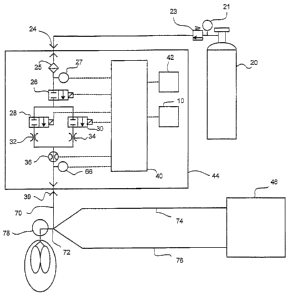
Turning now to Fig. 3, there is shown a schematic of a system that can be used
to carry out the present invention when the patient is breathing
spontaneously. As can
be seen, there is a patient device 18 that delivers the dosage of the
pharmaceutical gas
from the gas delivery system 22 to the patient 41 via a gas conducting conduit
19. As
indicated, the patient device 18 can be any one of a variety of devices that
actually
directs the pharmaceutical gas into the patient and may be a nasal cannala, a
maRk, an
endotracheal tube and the like.
With the Fig. 3 embodiment, there is a source of the pharmaceutical gas by
means of a gas supply tank 20 containing the pharmaceutical gas generally in a
carder
gas. When the pharrnac.eutical gas is carbon monoxide, for example, the
conventional, commercially available carrier gas is air. The supply of carbon
monoxide and air is provided in concentrations of 3000 ppm however,
concentrations
within the range of 1000 to 5000 ppm of CO in air are also possible
alternatives. In
the case of NO as the pharmaceutical gas, the carrier gas is conventionally
nitrogen
and the typical available concentrations range from 100 ppm to 1600 ppm.
Accordingly, from the supply tank 20, there is a tank pressure gauge 21 and a
regulator 23 to bring the tank pressure down to the working pressure of the
gas
delivery system 22. The pharmaceutical gas enters the gas delivery system 22
through
11
CA 02836041 2013-12-09
WO 2007/037975
PCT/US2006/035450
an inlet 24 that can provide a ready connection between that delivery system
22 and
the supply tank 20 via a conduit. The gas delivery system 22 has a filter 25
to ensure
no contaminants can interfere with the safe operation of the system and a
pressure
sensor 27 to detect if the supply pressure is adequate and thereafter includes
a gas shut
off valve 26 as a control of the pharmaceutical gas entering the deliver
system 22 and
to provide safety control in the event the delivery system 22 is over
delivering the
pharmaceutical gas to the patient. In the event of such over delivery, the
shut off
valve 26 can be immediately closed and an alarm 42 sounded to alert the user
that the
gas delivery system has been disabled. As such, the shut off valve 26 can be a
solenoid operated valve that is operated from signals directed from a central
processing unit including a microprocessor.
Downstream from the shut off valve 26 is a flow control system that controls
the flow of the pharmaceutical gas to the patient through the patient device
18. In the
embodiment shown, the flow control system comprises a high flow control valve
28
and a low control valve 30 and just downstream from the high and low flow
control
valves 28, 30, respectively, are a high flow orifice 32 and a low flow orifice
34 and
the purpose and use of the high and low flow valves 28, 30 and the high and
low flow
orifices 32,34 will be later explained. A gas flow sensor 36 is also located
in the flow
of pharmaceutical gas to the patient device 18 and, as shown, is downstream
from the
flow control system, however, the gas flow sensor 36 may alternatively be
located
upstream of the flow control system.
Next, there is a patient trigger sensor 38. When the patient breathes in
during
inspiration it creates a small sub atmospheric pressure in the nose or other
area where
the patient device 18 is located, and hence in the patient device 18 itself.
The patient
trigger sensor 38 detects this pressure drop and provides a signal indicative
of the start
of inspiration of the patient. Similarly, when the patient breathes out there
is a
positive pressure in the patient device 18 and the patient trigger sensor 38
detects that
positive pressure and provides a signal indicative of the beginning of
expiration. This
12
=
CA 02836041 2013-12-09
WO 2007/037975
PCT/CTS2006/035450
allows the patient trigger sensor 38 to determine not only the respiratory
rate of the
patient but also the inspiratory and expiratory times.
Finally there is a CPU 40 that communicates with the patient trigger sensor
38,
the high and low flow valves 28, 30, the gas shut off valve 26 and other
components
in order to carry out the purpose and intent of the present invention. The CPU
40 may
include a processing component such as a microprocessor to carry out all of
the
solutions to the equations that are used by the gas delivery system 22 to
deliver the
predetermined quantity of the pharmaceutical gas to a. patient The CPU 40 is
connected to the front panel 10 where the user can enter settings and monitor
therapy.
The use of the delivery system 22 of the present invention for spontaneous
breathing can now be explained. When the delivery system 22 detects by means
of
the patient trigger sensor 38 that inspiration has started, there is a signal
that is
provided to the CPU 40 to deliver a dose of a pharmaceutical gas (1µ11..- -00
breath ) into the
patient's inspiratory gas flow; preferably during the first 1/2 of the
inspiratory cycle.
This amount per breath has been determined based on the desired quantity of
pharmaceutical gas that has been set on the system and the calculations made
in a) to
g) described earlier.
The actual volume of gas delivered during the breath depends on the
concentration of the pharmaceutical gas in the carrier gas that is supplied by
the
supply tank 20. A typical source concentration (C00) for CO would be 3000 ppm
(range 500 to 5000). The volume of source gas (Vd) per breath to provide a
dose per
breath (MCO breath) when the source of CO is 3000 ppm is given by the
following
equation, combining equations 2,3, 4 and 6;
Vd = MCO breath- (28 = C,4.16 x1041) (8)
Given that
Vico = 60 x 103(g)
Coo = 3000 (ppm)
//breaths =600
Then Vd = 28.6 (mL)
13
CA 02836041 2013-12-09
WO 2007/037975
PCT/T1S2006/035450
To deliver the volume of source gas per breath (Vd), that is, the
pharmaceutical
, = =
gas and the carrier gas, the delivery system 22 opens a flow control valve,
such as
high flow valve 28 or low flow valve 30 to allow the gas to flow to the
patient until
the volume per breath (Vd) has been delivered The presence of the high flow
orifice
32 and the low flow orifice 36 limits the flow of gas to a fixed set level
during the
period that the high or low flow valves 28, 30 are open so the delivery system
22 can
determine the period of time the high or low flow valves 28, 30 should be open
to
deliver the volume per breath (Vd) required. Also, as another option, the flow
can be
determined by the gas flow sensor 36 to monitor the gas flow to the patient
device 18
and thus to the patient and can shut off the appropriate high or low flow
control valve
28, 30 when the desired predetermined quantity of pharmaceutical gas dose has
been
delivered to the patient.
As can be seen, to provide enough range to cover all the possible doses, the
use of multiple flow valves, that is, the high flow valve 28 and the low flow
valve 30
along with corresponding multiple orifices, high flow orifice 32 and low flow
orifice
34, can be used in parallel so as to provide high and low ranges of gas flow.
For
instance, the low flow gas flow through the low flow valve 30 could be set to
1 Li-min
and the high flow gas flow through the high flow control valve 28 could be set
to 6
Ltmin. The flow range of the particular gas flow valve is selected to ensure
that the
volume of gas per breath (Vd) can be delivered to the patient in at least V2
the
inspiratory time.
As an example, if the patient was breathing at 12 breaths per minute and had s
an LE ratio of 1:2 then the inspiratory time would be 1.66 seconds and half
that would
be 0.83 seconds.
The time (t) taken to deliver a Vd of 28 mL can be calculated as follows.
t = Vd . 60 /(Q. 1000) (secs) (9)
When Q (the flow of gas when the high flow valve 28 is open) =6 Limins
t = 0.28 (secs)
14
CA 02836041 2013-12-09
WO 2007/037975
PCFUS2006/035450
That time is therefore well within 1/2 the inspiratory time allowed of 0.83
, , =
seconds.
The delivery system 22 can also include monitoring and alarm features to alert
the user if the delivery system 22 is not working correctly. Those alarm
conditions
can be determined by the CPU 40 and the alarm 42 activated to alert the user
to the
particpiar fault condition. The alarm 42 can be audible, visual or both and
the Rinrm
conditions can be any one or all of the following:
No breath detected
Low source gas pressure
Inaccurate delivery of the volume per breath MO
Over delivery of the volume per breath (Vd)
Under delivery of the volume per breath MO
Under certain conditions, such as when the delivery system 22 is over
delivering the pharmaceutical gas, the CPU 40 may signal the gas shut off
valve 26
and immediately cease any further delivery of the pharmaceutical gas and the
alarm 42
also activated.
The use of the alarm 42 can also be an alternative to actually shutting off
the
supply of the pharmaceutical gas to a patient when the predetermined desired
quantity
of pharmaceutical gas has been fully delivered to the patient. In such case,
as an
alternative to ceasing the further supply of the pharmaceutical gas to the
patient, the
delivery system 22 may, by means of the CPU 40, activate the alarm 42 to alert
the
user that the total predetermined desired quantity of the pharmaceutical gas
has been
delivered. The user can then determine whether to manually deactivate the
delivery
system 22 or continue the delivery of the pharmaceutical gas under more
watchful
control of the patient's status.
Turning now to Fig. 4, there is shown a schematic view of a gas delivery
system
44 used in conjunction with a patient being breathed by a ventilator 46. In
the Fig. 4
CA 02836041 2013-12-09
WO 2007/037975
PCT/US2006/035450
embodiment, again there is a supply tank 20 that includes a conventional gas
regulator
=
23 and pressure gauge 21 to supply the pharmaceutical gas along with the
carrier gas to
an inlet 24 in the gas delivery system 44. Briefly summarizing the components
of the
Fig. 4 embodiment, since they are basically the same components as described
with
respect to the Fig. 3 embodiment, there can be a filter 25 and a pressure
sensor 27 in the
gas delivery system 44. Again there is a shut off valve 26 to control the
overall flow of
the pharmaceutical gas through the gas delivery system 44.
The high and low flow control valves 28 and 30 control the flow of the
pharmaceutical gas through the gas delivery system 44 and, the high and low
flow
valves 28, 30 operate as described with respect to the Fig. 3 embodiment with
high and
low flow orifices 32,34 located downstream of the flow control valves.
Again there is a gas flow sensor 36 and a patient trigger sensor 66, both of
which
communicate with the CPU 40. With this embodiment, however, the pharmaceutical
gas is carried through an outlet conduit 70 to a patient device 72 that also
receives the
breathing gas from the ventilator 46. As such, the ventilator 46 delivers a
flow of gas
through the inspiratory limb 74 and gas is returned to the ventilator 46
through the
expiratory limb 76.
The flow of gas from the ventilator 46 is thus supplemented by the flow of
pharmaceutical gas from the gas delivery system 44 where that gas is mixed at
or
proximate to the patient device 72 for introduction into the patient 78. Since
all of the
pharmaceutical gas is still delivered to the patient over the plurality of
breaths, basically
the CPU 40 can carry out the same determination of flows and the like as
explained with
respect to the Fig. 3 embodiment The main difference between this Fig. 4
embodiment,
and that shown in Fig. 3 is that the patient nigger sensor 66 is designed to
operate in a
way that works with a ventilator 46.
For instance, when the ventilator 46 provides gas flow to a patient during
inspiration, it causes a positive pressure in the breathing circuit. The
positive pressure is
conducted through the outlet conduit 70 and is detected by the patient trigger
sensor 66
16
CA 02836041 2013-12-09
WO 2007/037975
PCTIUS2006/035450
= = and is recognized as the start of inspiration. This is the
opposite to the embodiment of
Fig. 3 where the patient breathes spontaneously and a necrafive pressure is
generated
during inspiration in the patient device 18; this negative pressure is
conducted to the
patient trigger sensor 38 of Fig. 3 and is recognized as the start of
inspiration. As can be
appreciated, the patient trigger sensor 38 of Rci. 3 and the patient trigger
sensor of Hg. 4
could be the same pressure sensor and the Ms delivery system 44 can be set for
work
with a ventilator or a. spontaneously breathing patient
Those skilled in the art will readily recoani7e numerous adaptations and
moriifications which can be made to the phqrmarteutical gas delivery system
and method
of delivering a pharmaceutical gas of the present invention which will result
in an
improved method and system for introducing a known desired quantity of a
pharmaceutical gas into a patient The scope of the ciRims should not be
limited by the
preferred embodiments set forth in the examples, but should be given the
broadest
interpretation consistent with the description as a whole.
17