Note: Descriptions are shown in the official language in which they were submitted.
APNEA AND HYPOPNEA DETECTION USING BREATH PATTERN RECOGNITION
FIELD OF THE DISCLOSURE
[0001] The
present disclosure relates to the detection of breathing disorders, and in
particular, to a method and device for apnea and hypopnea detection.
BACKGROUND
[0002] Sleep
apnea (SA) is a breathing disorder characterized by repetitive complete or
partial cessations of breathing (apneas and hypopneas, respectively) during
sleep. The frequency
of these events ranges from 5 to 100 times/hour depending on the severity of
the case. As a result,
patients suffer from poor sleep quality, daytime sleepiness, and poor
cognitive performance.
Sleep apnea can generally be characterized as one of two types -obstructive
and central sleep
apnea (OSA and CSA, respectively). It has been observed that OSA, which is the
most common
type, increases the risk of developing hypertension, heart failure (HF), and
stroke by 3 to 4 fold.
Also, patients with untreated sleep apnea generally consume twice as many
healthcare resources
for treatment of cardio-respiratory diseases than subjects without the
disease. On the other hand,
it has been demonstrated that treating OSA in patients with hypertension or HF
lowers blood
pressure, .and dramatically improves cardiovascular function. Therefore,
diagnosing and treating
such patients could have a very substantial beneficial medical and public
health impact.
Unfortunately, the majority of people with sleep apnea remain undiagnosed due
to the lack of
accessibility to expensive overnight monitoring in a sleep laboratory
presently required for
diagnosis. Therefore, there is an increasing demand for developing reliable
yet simple tools for
diagnosing sleep apnea that can be accessed by a wider base of the population.
[0003]
Obstructive sleep apnea (OSA) is generally understood to result from partial
or
complete collapse of the pharynx or the upper airway (UA) resulting in
obstruction of the airflow
pathway. In OSA, the respiratory drive is still present but the patient is
breathing against a high
resistance tube _______________________________________________________ a
situation that mimics chocking. Thus, the hallmark of OSA is narrowing,
obstruction, or total closure of the upper airway
1
CA 2836164 2018-08-09
(pharynx). This results in characteristic breath sounds such as the occurrence
of snoring and
turbulent sounds. Each event generally lasts 10 to 60 seconds, thus generally
causing episodes of
oxygen deprivation and often provoking arousals from sleep and consequent
sleep fragmentation.
As a result, patients suffer from poor sleep quality, daytime sleepiness, and
impaired cognitive
performance. It is a common disease affecting approximately 7% of adults.
Nevertheless, the
majority of patients with OS A remain undiagnosed; in one study, it was shown
that 93% of
women and 82% of men with moderate to severe OSA had not been diagnosed.
[0004] Central sleep apnea (CSA), on the other hand, is generally
understood to occur
when there is a temporary cessation of respiratory output from the respiratory
neurons in the
brainstem to the muscles of respiration. This lack of respiratory muscle
activation causes a
temporary cessation of airflow (i.e. central apnea), during which there is no
respiratory
ventilation. In contrast to OSA, the upper airway is usually open during CSA,
and thus chocking
sounds and snoring are less likely to occur. When airflow resumes, snoring
does not necessarily
occur because the pharynx is usually not obstructed.
[0005] Presently, the standard means of identifying and diagnosing sleep
apnea is via
overnight polysomnography (PSG), in which the patients have to sleep in a
laboratory attached to
many monitoring electrodes under the supervision of a technician. PSG is
expensive and access
to it is limited, resulting in long waiting lists in the limited areas where
PSG is available.
[0006] For this reason, interest has been raised in devising new methods to
diagnose
sleeping disorders, such as SA. For example, acoustic analysis of respiratory
sounds has gained
an increasing role in the study of respiratory disorders such as in
identifying pathological
respiratory sounds including wheezes and crackles, and to study and locate the
site of snoring. In
some sleep studies, snoring sounds were captured above the mouth level, as
were tracheal
sounds, to study snoring, particularly as snoring is a component of the
disease itself and is
produced at the very location where narrowing and obstruction takes place.
2
CA 2836164 2018-08-09
[0007] Despite recent findings, snore-driven techniques have fundamental
limitations
from the clinical perspective. For instance, snoring does not necessarily
occur in all types of SA,
such as in CSA. Furthermore, snore-driven techniques generally fail to assess
the severity of an
identified condition. For example, while snoring is a hallmark of OSA, it
might not necessarily
take place with each apnea and hypopnea. Accordingly, assessing the disease
severity in terms of
frequency of apneas per hour might be underestimated if some apneas are missed
due to absence
of snoring, for example. As knowledge about the disease severity can be
beneficial in selecting an
appropriate treatment strategy, snore-driven techniques can be less than
ideal.
[0008] Accordingly, while some work has been done to detect the occurrence
of OSA
from snoring sounds, there remains much room for improvement, be it in the
development of a
reliable technique for detecting the occurrence of different types of SA
and/or in providing a
reliable approach for evaluating the severity of such occurrences, for
example. Demand is also
increasing for reliable apnea identification, characterization and/or
diagnostic techniques that can
be accessed by a wider base of the population, for example as compared to the
technician-assisted
PSG techniques currently implemented in dedicated sleep laboratories.
[0009] Therefore, there remains a need for a method and device for apnea
and hypopnea
detection that overcomes at least some of the drawbacks of known techniques,
or at least,
provides the public with a useful alternative.
[0010] This background information is provided to reveal information
believed by the
applicant to be of possible relevance to the invention. No admission is
necessarily intended, nor
should be construed, that any of the preceding information constitutes prior
art against the
invention.
SUMMARY
[0011] An object of the invention is to provide a method and device for apnea
and hypopnea
detection. In accordance with one embodiment of the invention, there is
provided method for
detecting apneas and hypopneas from a digitized breath sound
3
CA 2836164 2018-08-09
recording acquired from a candidate suspected of sleep apnea, the method
comprising: scanning
an amplitude profile of said digitized breath sound recording to identify a
prospect event
segment; evaluating characteristics of said prospect event segment for
consistency with one or
more preset apnea-specific criteria; classifying said prospect event segment
as representative of
an apnea upon it satisfying each of said one or more apnea-specific criteria;
evaluating said
prospect event characteristics for consistency with one or more preset
hypopnea-specific criteria
distinct from said apnea-specific criteria; and classifying said prospect
event segment as
representative of a hypopnea upon it satisfying each of said one or more
hypopnea-specific
criteria.
[0012] In accordance with one such embodiment, the method is automatically
implemented by one or more processors of a computing system, and further
comprises
outputting, via a user interface, an indication of a candidate's condition as
a function of each
classified apnea and hypopnea.
[0013] In accordance with another embodiment, there is provided a computer-
readable
medium comprising statements and instructions stored thereon for
implementation by one or
more processors of a computing system to detect apneas and hypopneas from a
digitized breath
sound recording acquired from a candidate suspected of sleep apnea, in
accordance with the steps
of the above method.
[0014] In accordance with another embodiment of the invention, there is
provided a
system for detecting apneas and hypopneas from a digitized breath sound
recording acquired
from a candidate suspected of sleep apnea, the system comprising: one or more
processors; a
computer-readable medium accessible by said one or more processors and having
stored thereon
statements and instructions executable thereby to operate on said recording in
accordance with
the above method.
[0015] In accordance with one such embodiment, the system further comprises
a face
mask having a microphone mounted thereon and reproducibly disposable, upon the
candidate
wearing the mask, at a distance above a nose and mouth area of the candidate
so to intercept and
capture expiratory airflow sounds emanating therefrom to be digitized for
processing.
4
CA 2836164 2018-08-09
[0016] In accordance with another embodiment of the invention,
there is provided a
method for identifying a hypopnea from a digitized breath sound recording
acquired from a
candidate suspected of sleep apnea, the method comprising: identifying a low
amplitude segment
in a breath amplitude profile of the recording; calculating a decreasing
profile amplitude gradient
leading to said low amplitude segment; and classifying said low amplitude
segment as a
hypopnea only upon said decreasing profile amplitude gradient exceeding a
preset minimum
gradient.
[0017] In accordance with one such embodiment, the method is
automatically
implemented by one or more processors of a computing system, and further
comprises
outputting, via a user interface, an indication of each said classified
hypopnea:
[0018] In accordance with another embodiment, there is provided
a method for
automatically determining a sleep apnea severity index from a digitized breath
sound recording
acquired from a candidate suspected of sleep apnea, the method comprising:
scanning an
amplitude profile of said digitized breath sound recording to identify a
prospect event segment;
evaluating characteristics of said prospect event segment for consistency with
at least one of: one
or more preset apnea-specific criteria, and one or more preset hypopnea-
specific criteria distinct
from said apnea-specific criteria; increasing an apneic event count upon said
prospect event
segment satisfying each of said one or more apnea-specific criteria or each of
said one or more
hypopnea-specific criteria; repeating said steps for multiple prospect event
segments; and
determining the sleep apnea severity index as a function of a total apneic
event count.
[0019] In accordance with another embodiment, there is provide
a system for
automatically determining a sleep apnea severity index from a digitized breath
sound recording
acquired from a candidate suspected of sleep apnea, the system comprising: one
or more
processors; and a computer-readable medium accessible by said one or more
processors and
having stored thereon statements and instructions executable thereby to
operate on said recording
in accordance with the above method.
[0020] In accordance with one aspect, there is provided a
computer-implemented method,
automatically implemented by one or more processors of a computing system, for
detecting
apneas and hypopneas from a digitized breath sound recording acquired from a
candidate
CA 2836164 2018-08-09
1
suspected of sleep apnea, the method comprising: scanning by at least one
processor an
amplitude profile of said digitized breath sound recording to identify a
prospect event segment;
evaluating by at least one processor characteristics of said prospect event
segment for consistency
with one or more preset apnea-specific criteria; classifying by at least one
processor said prospect
event segment as representative of an apnea upon it satisfying each of said
one or more apnea-
specific criteria; evaluating by at least one processor said prospect event
characteristics for
consistency with one or more preset hypopnea-specific criteria distinct from
said apnea-specific
criteria; and classifying by at least one processor said prospect event
segment as representative of
a hypopnea upon it satisfying each of said one or more hypopnea-specific
criteria; and outputting
indication of a candidate's condition as a function of each said classified
apnea and hypopnea;
wherein said prospect event is characterized by a falling edge and a rising
edge temporally
separated by a low-amplitude segment; wherein said one or more apnea-specific
criteria comprise
a minimum apnea event amplitude depth threshold; and wherein said one or more
hypopnea-
specific criteria comprise a distinct minimum hypopnea event amplitude depth
threshold
shallower than said minimum apnea event amplitude depth threshold, and wherein
said distinct
hypopnea event amplitude depth threshold comprises both a minimum pre-apneic
depth threshold
and a distinct post-apneic depth threshold.
[0021]
According to one aspect, there is provided a non-transitory computer-readable
medium comprising statements and instructions stored thereon for
implementation by one or
more processors of a computing system to detect apneas and hypopneas from a
digitized breath
sound recording acquired from a candidate suspected of sleep apnea that cause
the computer
system to perform the following operations: scan by at least one processor an
amplitude profile of
said digitized breath sound recording to identify a prospect event segment;
evaluate by at least
one processor characteristics of said prospect event segment for consistency
with one or more
preset apnea-specific criteria; classify by at least one processor said
prospect event segment as
representative of an apnea upon it satisfying each of said one or more apnea-
specific criteria;
evaluate by at least one processor the characteristics of said prospect event
for consistency with
one or more preset hypopnea-specific criteria distinct from said apnea-
specific criteria; classify
by at least at least one processor said prospect event segment as
representative of a hypopnea
upon it satisfying each of said one or more hypopnea-specific criteria; and
output indication of a
candidate's condition as a function of each said classified apnea and
hypopnea; wherein said
6
CA 2836164 2018-08-09
prospect event is characterized by a falling edge and a rising edge temporally
separated by a low-
amplitude segment; wherein said one or more apnea-specific criteria comprise a
minimum apnea
event amplitude depth threshold; and wherein said one or more hypopnea-
specific criteria
comprise a distinct minimum hypopnea event amplitude depth threshold shallower
than said
minimum apnea amplitude depth threshold, and wherein said distinct hypopnea
event amplitude
depth threshold comprises both a minimum pre-apneic depth threshold and a
distinct post-apneic
depth threshold.
[0022] According to one aspect, there is provided a system for detecting
apneas and
hypopneas from a digitized breath sound recording acquired from a candidate
suspected of sleep
apnea, the system comprising: one or more processors; memory storing
instructions, the
instructions comprising instructions that, when executed by the one or more
processors, cause the
processors to: scan by at least one processor an amplitude profile of said
digitized breath sound
recording to identify a prospect event segment; evaluate by at least one
processor characteristics
of said prospect event segment for consistency with one or more preset apnea-
specific criteria;
classify by at least one processor said prospect event segment as
representative of an apnea upon
it satisfying each of said one or more apnea-specific criteria; evaluate by at
least one processor
the characteristics of said prospect event for consistency with one or more
preset hypopnea-
specific criteria distinct from said apnea-specific criteria; classify by at
least one processor said
prospect event segment as representative of a hypopnea upon satisfying each of
said one or more
hypopnea-specific criteria; and output indication of a candidate's condition
as a function of each
said classified apnea and hypopnea; wherein said prospect event is
characterized by a falling
edge and a rising edge temporally separated by a low-amplitude segment;
wherein said one or
more apnea-specific criteria comprise a minimum apnea event amplitude depth
threshold; and
wherein said one or more hypopnea-specific criteria comprise a distinct
minimum hypopnea
event amplitude depth threshold shallower than said minimum apnea amplitude
depth threshold,
and wherein said distinct hypopnea event amplitude depth threshold comprises
both a minimum
pre-apneic depth threshold and a distinct post-apneic depth threshold.
[0023] According to one aspect, there is provided a computer-implemented
method,
automatically implemented by one or more processors of a computing system, for
detecting
apneas and hypopneas from a digitized breath sound recording acquired from a
candidate
7
CA 2836164 2018-08-09
suspected of sleep apnea, the method comprising: scanning by at least one
processor an
amplitude profile of said digitized breath sound recording to identify a
prospect event segment;
evaluating by at least one processor characteristics of said prospect event
segment for consistency
with one or more preset apnea-specific criteria; classifying by at least one
processor said prospect
event segment as representative of a hypopnea upon it satisfying each of said
one or more
hypopnea-specific criteria; and outputting indication of a candidate's
condition as a function of
each said classified apnea and hypopnea; wherein said prospect event is
characterized by a falling
edge and a rising edge temporally separated by a low-amplitude segment;
wherein said one or
more apnea-specific criteria comprise a minimum apnea event amplitude depth
threshold;
wherein said one ore more hypopnea-specific criteria comprise a distinct
minimum hypopnea
event amplitude depth threshold shallower than said minimum apnea event
amplitude depth
threshold; and wherein said scanning step comprises scanning said amplitude
profile for
segments satisfying a minimum prospect event depth threshold, said minimum
prospect event
depth threshold at least as shallow as said minimum hypopnea event amplitude
depth threshold.
[0024]
According to one aspect, there is provided a system for detecting apneas and
hypopneas form a digitized breath sound recording acquired from a candidate
suspected of sleep
apnea, the system comprising: one or more processors; memory storing
instructions, the
instructions comprising instructions that, when executed by the one or more
processors, cause the
processors to: scan by at least one processor an amplitude profile of said
digitized breath sound
recording to identify a prospect event segment; evaluate by at least one
processor characteristics
of said prospect event segment for consistency with one or more preset apnea-
specific criteria;
classify by at least one processor said prospect event segment as
representative of an apnea upon
it satisfying each of said one or more apnea-specific criteria; evaluate by at
least one processor
the characteristics of said prospect event for consistency with one or more
preset hypopnea-
specific criteria distinct from said apnea-specific criteria; classify by at
least one processor said
prospect event segment as representative of a hypopnea upon it satisfying each
of said one or
more hypopnea-specific criteria; and output indication of a candidate's
condition as a function of
each said classified apnea and hypopnea; wherein said prospect event is
characterized by a falling
edge and a rising edge temporally separated by a low-amplitude segment;
wherein said one or
more apnea-specific criteria comprise a minimum apnea event amplitude depth
threshold;
wherein said one or more hypopnea-specific criteria comprise a distinct
minimum hypopnea
8
CA 2836164 2018-08-09
event amplitude depth threshold shallower than said minimum apnea amplitude
depth threshold;
and wherein said scanning step comprises scanning said amplitude profile for
segments satisfying
a minimum prospect event depth threshold, said minimum prospect event depth
threshold, said
minimum prospect event depth threshold at least as shallow as said minimum
hypopnea event
amplitude depth threshold.
[0025] According to one aspect, there is provided a non-transitory computer-
readable
medium comprising statements and instructions stored thereon for
implementation by one or
more processors of a computing system to detect apneas and hypopneas from a
digitized breath
sound recording acquired from a candidate suspected of sleep apnea that cause
the computer
system to perform the following operations: scan by at least one processor an
amplitude profile of
said digitized breath sound recording to identify a prospect event segment;
evaluate by at least
one processor characteristics of said prospect event segment for consistency
with one or more
preset apnea-specific criteria; classify by at least one processor said
prospect event segment as
representative of an apnea upon it satisfying each of said one or more apnea-
specific criteria;
evaluate by at least one processor the characteristics of said prospect event
for consistency with
one more preset hypopnea-specific criteria distinct from said apnea-specific
criteria; classify by
at least one processor said prospect event segment as representative of
hypopnea upon it
satisfying each of said one or more hypopnea-specific criteria; and output
indication of a
candidate's condition as a function of each said classified apnea and
hypopnea; wherein said
prospect event is characterized by a falling edge and a rising edge temporally
separated by a low-
amplitude segment; wherein said one or more apnea-specific criteria comprise a
minimum apnea
event amplitude depth threshold; wherein said one or more hypopnea-specific
criteria comprise a
distinct minimum hypopnea event amplitude depth threshold shallower than said
minimum apnea
amplitude depth threshold; and wherein said scanning step comprises scanning
said amplitude
profile for segments satisfying a minimum prospect event depth threshold, said
minimum
prospect event depth threshold, said minimum prospect event depth threshold at
least as shallow
as said minimum hypopnea event amplitude depth threshold.
[0026] Other aims, objects, advantages and features of the invention will
become more
apparent upon reading of the following non-restrictive description of specific
embodiments
thereof, given by way of example only with reference to the accompanying
drawings.
9
CA 2836164 2018-08-09
BRIEF DESCRIPTION OF THE FIGURES
[0027] Several embodiments of the present disclosure will be provided, by
way of
examples only, with reference to the appended drawings, wherein:
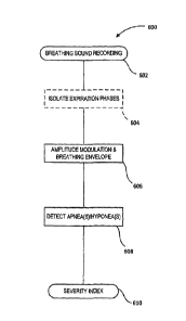
[0028] Figure 1 is a diagram of an apnea and hypopnea detection system, in
accordance
with one embodiment of the invention;
[0029] Figure 2 is a perspective view of a mask for use in acquiring
breathing sounds
from a candidate, for example within the context of the system of Figure 1, in
accordance with
one embodiment of the invention;
[0030] Figures 3 and 4 are front and side views, respectively, of a mask
for use in
acquiring breathing sounds from a candidate, for example within the context of
the system of
Figure 1, in accordance with another embodiment of the invention;
[0031] Figure 5 is a schematic diagram of a breathing sound
recording/processing device,
for use for example within the context of the system of Figure 1, in
accordance with one
embodiment of the invention.
[0032] Figure 6 is a high level flow diagram of a method for apnea and
hypopnea
detection, in accordance with one embodiment of the invention;
[0033] Figure 7A is an illustrative waveform plot of breathing sounds
acquired from a
single breath showing both an inspiration phase and an expiration phase,
whereas Figures 7B and
7C are exemplary FFT spectra for respective time segments of the inspiration
phase and
expiration phase of Figure 7A, in accordance with one embodiment of the
invention;
[0034] Figure 8 is a high level flowchart of a method for identifying
apneas and
hypopneas from digitized breathing sounds, in accordance with one embodiment
of the
invention;
CA 2836164 2018-08-09
[0035] Figure 9 is a plot of exemplary ventilation breathing sounds and
apneic periods,
represented by a train of digitized signal peaks, in accordance with one
embodiment of the
invention;
[0036] Figures 10A to 10C are plots of successively preprocessed digitized
breathing
sounds, wherein Figure 10B is a plot of the digitized breathing sounds of
Figure 10A with
outliers removed and a segment thereof defined for segment-based
normalization, and wherein
Figure 10C is a plot of the digitized breathing sounds of Figure 10B after
segment-based
normalization, in accordance with one embodiment of the invention;
[0037] Figure 11 is an exemplary plot of an identified prospect event (PE)
showing
relation between rectified digitized breathing sounds (BS) and a breathing
envelope (BE) thereof,
as well as an extracted breathing effort envelope (EE) taken therefrom and its
various
components, in accordance with one embodiment of the invention;
[0038] Figure 12 is a flowchart of illustrative apnea and hypopnea tests
executed within
the context of the method of Figure 8, in accordance with one embodiment of
the invention;
[0039] Figure 13 is a flowchart of an exemplary method for classifying
apneas and
hypopneas from identified prospect events, in accordance with one embodiment
of the invention;
[0040] Figures 14A and 14B are plots of a three minute segment of sample
breath sound
data showing raw waveform and envelope profile data respectively;
[0041] Figures 15A and 15B are plots of illustrative envelope profile data
for an apneic
and a hypopneic event, respectively;
[0042] Figure 16 is a plot depicting high level of agreement between Apnea-
Hypopnea
Index (A111) as achieved using a method according to one embodiment of the
invention (AHI-a),
and Atli as measured by practitioners using a conventional PSG method (AHI-p);
[0043] Figures 17A and 17B are plots showing a distribution of AHI-a and 3
AHI-p
scores as a function of the mean All-p score, obtained according TV50 and AASM
standards,
respectively; and
11
CA 2836164 2018-08-09
[0044] Figure 18 is a Bland Altman plot showing AHI-a scores falling within
Limits of
Agreement with respect to AHI-p scores.
DETAILED DESCRIPTION
[0045] With reference to the disclosure herein and the appended figures, a
method and
apparatus for apnea and hypopnea detection are described in accordance with
different
embodiments of the invention. For instance, and as will be discussed in
greater detail below, the
methods and devices described herein according to different embodiments of the
invention, allow
to automate at least some of the analyses/evaluations associated with the
detection of breathing
disorders such as apnea and hypopnea, using breath sound recordings. For
example, recordings of
an individual's breath-related sounds during sleep can be recorded and
analyzed, using at least
some of the methods described herein, to detect and identify distinct apneas
and hypopneas for
the purpose of diagnosing this individual's breathing disorder(s) and
providing adequate
treatment therefor.
[0046] In some embodiments, such methods and devices rely, at least in
part, on the
analysis of breath-related sounds. For example, in some embodiments, the
methods and devices
described herein can be used to detect sleep apnea via acoustic breath sound
analysis, such as
from overnight breath sound recordings and the like, and in some embodiments,
to further
quantify a severity of this disorder in a given subject, and/or achieve other
related
characterizations of the subject's condition. Such results present significant
improvements in the
provision of a less invasive approach to sleep apnea identification,
characterization ancUor
diagnosis, particularly as compared to PSG and other such techniques. Namely,
and in
accordance with some embodiments, useable results can be achieved using as few
as a single
non-invasive acoustic breathing sound channel to achieve sleep apnea
identification,
characterization and/or diagnosis, which may further include characterization
of a severity of the
identified apnea. In some embodiments such results may be achieved
irrespective of the type of
apnea experienced by the candidate (e.g. OSA and/or CSA).
[0047] With reference now to Figure 1, a system for apnea and/or hypopnea
detection,
generally referred to using the numeral 100, and in accordance with an
illustrative embodiment of
the invention, will now be described. In this embodiment, the system 100
generally provides for
12
CA 2836164 2018-08-09
the recordal of breath sound data, in this example, via one or more
transducers, such as
microphone 102, disposed at a distance A from a nose and mouth area of a
candidate's face in a
face mask 112 to be worn by the candidate during testing. For example, the
mask may be worn
during sleep if seeking to identify sleep-related disorders such as sleep
apnea. As schematically
depicted, the one or more transducers 102 are operatively coupled to a data
recording/processing
module 120 for recording breath sound data, illustratively depicted by raw
signal plot 130, for
processing.
[0048] In this example, the microphone 102 is coupled in or to a loose
fitting full face
mask 112 which includes at least one opening 114 to allow for ease of
breathing, and provides for
a communication path 118, be it wired and/or wireless, from the microphone 102
to the
recording/processing module 120.
[0049] Figure 2 provides another example of a mask 200 usable in acquiring
breathing
sounds suitable in the present context. In this example, the mask 200
generally comprises at least
one transducer, such as microphones 202 and 204, and a support structure 206
for supporting
same above a nose and mouth area of the subject's face. The support structure
206 is generally
shaped and configured to rest on the subject's face and thereby delineate the
nose and mouth area
thereof, and comprises two or more outwardly projecting limbs 208 (e.g. three
limbs in this
example) that, upon positioning the mask 200, converge into a transducer
supporting portion 210
for supporting microphones 202 and 204 at a distance from this area.
[0050] The support structure further comprises an optional frame 212 and
face resting
portion 214 shaped and configured to contour the face of the subject and at
least partially
circumscribe the nose and mouth area of the subject's face, thereby
facilitating proper positioning
of the mask on the subject's face and providing for greater comfort. A
restraining mechanism,
such as head straps 216 and 218, can be used to secure the mask to the
subject's face and thereby
increase the likelihood that the mask will remain in the proper position and
alignment during use,
e.g. even when the subject is sleeping in monitoring certain breathing
disorders such as sleep
apnea.
[0051] In this embodiment, the mask 200 further comprises an integrated
recording
device 220, such as a digital recording device or the like, configured for
operative coupling to the
13
CA 2836164 2018-08-09
at least one transducer, such as microphones 202 and 204, such that sound
and/or airflow signals
generated by the at least one transducer can be captured and stored for
further processing, for
example via one or more data processing modules (not shown). In this
particular embodiment, the
recording device 220 is disposed on a frontal member 222 of the support
structure 206, thereby
reducing an obtrusiveness thereof while remaining in close proximity to the at
least one
transducer so to facilitate signal transfer therefrom for recordal. In
providing an integrated
recording device, the mask 200 can effectively be used as a self-contained
respiratory monitoring
device, wherein data representative of the subject's breathing can be stored
locally on the mask
and transferred, when convenient, to a remotely located respiratory diagnostic
center, for
example. Further details as to the design, features and use of mask 200 are
provided in U.S.
Patent Application Publication No. 2011/0092839 and International Application
Publication No.
WO 2012/037641.
[0052] Figures 3 and 4 provide yet another example of a mask 300 usable in
acquiring
breathing sounds suitable in the present context. In this example, the mask
300 comprises at least
one transducer, such as microphone 302, and a support structure 306 for
supporting same above a
nose and mouth area of the subject's face. The support structure 306 is
generally shaped and
configured to rest on the subject's face and extend outwardly therefrom over a
nose and mouth
area thereof to provide a transducer supporting portion 310 for supporting the
microphone 302,
upon positioning the mask, at a distance from this area.
[0053] In this example, the support structure 306 is shaped and configured
to support the
transducer 302 above the nose and mouth area at a preset orientation in
relation thereto, wherein
the preset orientation may comprise one or more of a preset position and a
preset angle to
intercept airflow produced by both the subject's nose and mouth. For example,
in one
embodiment, the preset orientation may be preset as a function of an estimated
intersection
between nasal and oral airflow, for example based on an observed or calculated
average
intersection between such airflows. For instance, in one embodiment, the
preset orientation may
comprise a preset position that, upon positioning the mask on the subject's
face, is substantially
laterally centered relative to the subject's face and longitudinally
substantially in line with or
below the subject's mouth, thus generally intercepting oral and nasal airflow.
14
CA 2836164 2018-08-09
[0054] In a same or alternative embodiment, the preset orientation may
comprise a preset
angle that aligns the microphone, or a principle responsiveness axis thereof,
along a line more or
less representative of an averaging between general oral and nasal airflows.
For instance, in one
embodiment, the orientation angle is preset to more or less bisect an angle
formed by the
transducer's preset position relative to the subject's nose (i.e. nostrils)
and mouth. This bisecting
angle, which should be construed within the present context to represent an
angle more or less
directing the transducer's principal responsiveness axis toward a point
somewhere between the
wearer's nose and mouth, may be determined as a function of measured, observed
and/or
otherwise estimated nasal and oral breathing patterns, so to improve or
enhance the transducer's
general responsiveness to airflow originating from the nose and/or mouth of
the candidate.
Generally, the preset orientation may thus, in accordance with one embodiment,
of the invention,
comprise a preset angle that, upon positioning the mask on the subject's face,
substantially aligns
the transducer with a point between the subject's nose and mouth.
[0055] In this embodiment, the support structure 306 generally comprises
two outwardly
projecting limbs that flow continuously one within the other toward the
transducer supporting
portion 310 in defining a funneling shape that substantially converges toward
this transducer
supporting portion, thus effectively redirecting nasal and/or oral airflow
toward the transducer
302 and allowing for effective monitoring of airflow produced by both the
subject's nose and
mouth while breathing. Accordingly, breathing airflow, which will generally
more or less diverge
laterally from the candidate's nostrils as it is projected more or less
obliquely downward
therefrom, can be effectively collected, at least partially, by the generally
concave support
structure 306 to be substantially funneled thereby toward the transducer 302.
Accordingly, in this
embodiment, not only is the transducer's preset orientation generally selected
as a function of an
estimated nasal and oral airflow intersection, the general funneling shape of
the support structure
306 will further redirect at least a portion of laterally diverging nasal (and
oral) airflow toward
the transducer 302. Similarly, though not explicitly depicted herein, the same
generally concave
shape of the funneling support structure 306 will, partly due to its upwardly
titled orientation in
this embodiment, also at least partially redirect longitudinally divergent
airflow toward the
transducer 302.
CA 2836164 2018-08-09
[0056] The transducer supporting portion 310 of the support structure 306
further
comprises one or more (three in this embodiment) transducer supporting bridges
or limbs 326
extending from a transducer-surrounding aperture 328 defined within the
support structure 306.
In this embodiment, the provision of bridging limbs 326 may allow for a
general reduction in
airflow resistance, which may result in substantially reduced dead space. For
example, while the
general funneling shape of the support structure 306 allows for a redirection
of airflow toward the
transducer 302, the bridged aperture 328 allows for this flow of air to
continue beyond the
transducer 302, and thereby reduce the likelihood of this flowing air pooling
within the mask
and/or flowing back onto itself, which could otherwise lead to a generally
uncomfortable
warm/humid flow of breath back in the candidate's face (and which could thus
be breathed in
again), and/or lead to unusual flow patterns and/or sounds that could further
complicate data
processing techniques in accounting for these patterns.
[0057] The support structure 306 further comprises an optional frame 312 and
face resting
portion 314 shaped and configured to contour the face of the subject and at
least partially
circumscribe the nose and mouth area of the subject's face, thereby
facilitating proper positioning
of the mask on the subject's face and providing for greater comfort. A
restraining mechanism,
such as head straps 316, can be used to secure the mask to the subject's face
and thereby increase
the likelihood that the mask will remain in the proper position and alignment
during use, even
when the subject is sleeping, for example, in monitoring and diagnosing
certain common
breathing disorders. It will be appreciated that the data analysis techniques
described below may
also be applicable, in some conditions, in monitoring and diagnosing a
subject's breathing when
awake.
[0058] In this embodiment, the mask 300 further comprises a recording
device 320, such
as a digital recording device or the like, configured for operative coupling
to the at least one
transducer 302, such that breath sound signals generated by the at least one
transducer can be
captured and stored for further processing. In this particular embodiment, the
recording device
320 is disposed on one of the limbs of the support structure 306, thereby
reducing an
obtrusiveness thereof while remaining in close proximity to the at least one
transducer so to
facilitate signal transfer therefrom for recordal. A battery pack 324,
operatively coupled to the
recording device 320, is provided on a frontal member 322 of the mask 300 to
power the
16
CA 2836164 2018-08-09
recording device and transducer in acquiring data free of any external wiring
or the like. In
providing an integrated and self-supported recording device, the mask 300 can
effectively be
used as a self-contained respiratory monitoring device, wherein data
representative of the
subject's breathing can be stored locally on the mask and transferred, when
convenient, to a
remotely located respiratory diagnostic center, for example.
[0059] Further details as to the design, features and use of mask 300 are
provided in
International Application Publication No. WO 2012/037641.
[0060] As will be appreciated by the person of ordinary skill in the art,
the general shape
and design of the above-described masks (200, 300) can provide, in different
embodiments, for
an improved responsiveness to airflow produced by the subject while breathing,
and that
irrespective of whether the subject is breathing through the nose or mouth,
predominantly
through one or the other, or through both substantially equally. Namely, the
ready positioning of
an appropriate transducer responsive to airflow relative to the nose and mouth
area of the
subject's face is provided for by the general spatial configuration of these
masks. Accordingly,
great improvements in data quality, reliability and reproducibility can be
achieved, and that,
generally without the assistance or presence of a health care provider, which
is generally required
with previously known systems.
[0061] Furthermore, it will be appreciated that different manufacturing
techniques and
materials may be considered in manufacturing the above and similar masks, for
example as
described below, without departing from the general scope and nature of the
present disclosure.
For example, the entire mask may be molded in a single material, or fashioned
together from
differently molded or otherwise fabricated parts. For example, the outwardly
projecting nosepiece
of the mask may comprise one part, to be assembled with the frame and face-
resting portion of
the mask. Alternatively, the frame and nosepiece may be manufactured of a
single part, and fitted
to the face-resting portion thereafter. As will be further appreciated, more
or less parts may be
included in different embodiments of these masks, while still providing
similar results. For
example, the nose piece, or an equivalent variant thereto, could be
manufactured to rest directly
on the subject's face, without the need for a substantial frame or face
resting portions.
17
CA 2836164 2018-08-09
Alternatively or in addition, different numbers of outwardly projecting limbs
(e.g. two, three,
four, etc.) or structures may be considered to provide similar results.
[0062] In general, the at least one transducer in the above examples, and
their equivalents,
is responsive to sound and/or airflow for generating a data signal
representative of breathing
sounds to be used in implementing different embodiments of the below-described
methods. For
example, in the illustrated embodiment of Figure 2, two microphones 202 and
204 are provided
in the transducer support portion 210, wherein one of these microphones may be
predominantly
responsive to sound, whereas the other may be predominantly responsive to
airflow. For
example, the microphone configured to be predominantly responsive to airflow
may be more
sensitive to air pressure variations then the other. In addition or
alternatively, the microphone
configured to be predominantly responsive to sound may be covered with a
material that is not
porous to air. In addition or alternatively, the microphone configured to be
predominantly
responsive to sound may be oriented away from the subject's nose and mouth so
to reduce an air
impact on the diaphragm of this microphone produced by the subject's breathing
airflow. In other
embodiments, a microphone predominantly responsive to airflow may be
positioned in the
transducer support portion in line with the subject's nose and mouth, while
another microphone
may be positioned to the side or on the periphery of the mask to thereby
reduce an influence of
airflow thereon. In some of these embodiments, the recorded sound from the
peripheral
microphone, or again from the microphone predominantly responsive to sound,
may in fact be
used to isolate the airflow signal recorded in the nosepiece, by filtering out
the sound signal
recorded thereby, for example.
[0063] In the embodiments of Figures 1, 3 and 4, however, a single
microphone may
alternatively be used to capture both sound and airflow, wherein each signal
may be optionally
distinguished and at least partially isolated via one or more signal
processing techniques, for
example, wherein a turbulent signal component (e.g. airflow on microphone
diaphragm) could be
removed from other acoustic signal components (e.g. snoring). Such techniques
could include,
but are not limited to adaptive filtering, harmonics to noise ratio, removing
harmonics from a
sound recording, wavelet filtering, etc.
18
CA 2836164 2018-08-09
[0064] In each of the above examples, the device may be implemented using a
single type
of transducer, for example one or more microphones which may in fact be
identical. It will be
appreciated however that other types of transducers, particularly responsive
to airflow, may be
considered herein without departing from the general scope and nature of the
present disclosure.
For example, a pressure sensor or airflow monitor may be used instead of a
microphone to yield
similar results in capturing an airflow produced by the subject while
breathing.
[0065] It will be appreciated by the skilled artisan that different types
of masks, or other
means for recording breath sounds, may be considered herein without departing
from the general
scope and nature of the present disclosure. Namely, while the above examples
provide for one
means for acquiring breath sound data in implementing the below-described
analysis methods,
other means will be readily apparent to the person of ordinary skill in the
art and should thus be
considered to fall within the context of the present disclosure.
[0066] In the above examples, acquired breath sound data is generally
communicated to
data recording/processing module 120, 220, 320, which may comprise a single
self-contained
module, or a number of distinct and communicatively coupled or coupleable
modules configured
to provide complimentary resources in implementing the below-described
methods. Namely, the
recording/processing module may comprise a distinctly implemented device
operatively coupled
to one or more breath sound transducers for communication of data acquired
thereby via, for
example, one or more data communication media such as wires, cables, optical
fibres, and the
like, and/or one or more wireless data transfer protocols, as would be readily
appreciated by one
of ordinary skill in the art. A distinct recording module may, however, in
accordance with
another embodiment, be implemented integrally with the mask, and used to later
communicate
recorded data, be it raw and/or preprocessed data, to a remote or distinct
processing device. As
will be appreciated by the skilled artisan, the processing module may further
be coupled to, or
operated in conjunction with, an external processing and/or interfacing
device, such as a local or
remote computing device or platform provided for the further processing and/or
display of raw
and/or processed data, or again for the interactive display of system
implementation data,
protocols and/or diagnostics tools.
19
CA 2836164 2018-08-09
[0067] With reference to Figure 5, the processing module, depicted herein
generically as
a self-contained recording/processing device 500, generally comprises a power
supply 502, such
as a battery or other known power source, and various input/output port(s) 504
for the transfer of
data, commands, instructions and the like with interactive and/or peripheral
devices and/or
components (not shown), such as for example, a breath monitoring mask or the
like (as shown in
Figures 1 to 4), external data processing module, display or the like.
[0068] The device 500 further comprises one or more computer-readable media
508
having stored thereon statements and instructions, for implementation by one
or more processors
506, in automatically implementing various computational tasks with respectto,
for example,
breath sound data acquisition and processing. Such tasks may include, but are
not limited to, the
implementation of one or more breathing disorder identification,
characterization and/or
diagnostic tools implemented on or in conjunction with the device 500. In the
illustrative
example of Figure 5, these statements and instructions are represented by
various sub-modules
and/or subroutines to be called upon by the processors 506 to operate the
device in recording and
processing breathing sounds in accordance with the various breath disorder
identification,
characterization and diagnostic methods discussed below. Illustratively, the
processing platform
will include one or more acquisition module(s) 510 for enabling the
acquisition and digitization
of breath sounds generated by the candidate while breathing; one or more
processing module(s)
512 for processing the acquired data in identifying, characterizing and/or
diagnosing a potential
breathing disorder; one or more admin, module(s) 516 for receiving as input
various processing
parameters, thresholds and the like, which may be varied from time to time
upon refinement
and/or recalibration of the system or based on different user or candidate
characteristics; and one
or more output module(s) 514 configured to output process results in a useable
form, either for
further processing, or for immediate consumption (e.g. breath disorder
identification,
characterization and/or diagnosis results, indicia, and the like). For the
purpose of illustration, the
processing module(s) 512 in this particular example, and with reference to the
high level and
detailed processes of Figures 6 and 8, respectively, may include, but are not
limited to, an
optional breath cycle identification module 518 (e.g. to identify and isolate
expiratory breathing
phases), a breath sound amplitude modulation module 520, a breathing effort
extraction module
522 (e.g. to identify prospective events based on observed breathing effort
variations),
apnea/hypopnea test modules 524/526, and an event identification module 528
(e.g. to generate
CA 2836164 2018-08-09
an event identification, overall count and/or severity index such as a apnea-
hypopnea index -
AH1), to name a few examples. It will be appreciated that different
embodiments may implement
different subsets and combinations of the above modules to achieve different
results depending
on the intended purpose of the device and/or known or suspected candidate
conditions.
Furthermore, while riot explicitly illustrated, one or more of the above-noted
processing modules
may be equally subdivided into one or more submodules consistent with preset
processes to be
implemented thereby, for example as described hereinbelow in accordance with
different
illustrative embodiments of the invention. Clearly, while the above
contemplates the provision of
a modular processing architecture, other process architectures may be readily
applied to the
present context, as will be appreciated by the person of ordinary skill in the
art, without departing
from the general scope and nature of the present disclosure.
[0069] The device 500 may further comprise a user interface 530, either
integral thereto,
or distinctly and/or remotely operated therefrom for the input of data and/or
commands (e.g.
keyboard, mouse, scroll pad, touch screen, push-buttons, switches, etc.) by an
operator thereof,
and/or for the presentation of raw, processed and/or diagnostic data with
respect to
apnea/hypopnea detection, monitoring and/or diagnostic (e.g. graphical user
interface such as
CRT, LCD, LED screen or the like, visual and/or audible signals / alerts /
warnings / cues,
numerical displays, etc.).
[0070] As will be appreciated by those of ordinary skill in the art,
additional and/or
alternative components operable in conjunction and/or in parallel with the
above-described
illustrative embodiment of device/module 500 may be considered herein without
departing from
the general scope and nature of the present disclosure. It will further be
appreciated that
device/module 500 may equally be implemented as a distinct and dedicated
device, such as a
dedicated home, clinical or bedside apnea/hypopnea detection device, or again
implemented by a
multi-purpose device, such as a multi-purpose clinical or bedside device, or
again as an
application operating on a conventional computing device, such as a laptop or
PC, or other
personal computing devices such as a PDA, smartphone, or the like.
[0071] Furthermore, it will be appreciated that while a single all-
encompassing device
500 is schematically depicted herein, various functionalities and features of
the device may rather
21
CA 2836164 2018-08-09
be distributed over multiple devices operatively and/or communicatively
coupled to achieve a
similar result. For example, in one embodiment, at least part of the
functionalities of device 500
will be implemented on a local processing device integral to a self-contained
breath monitoring
mask, such as depicted by the embodiments of Figures 2 to 4. In such
embodiments, the power
supply, such as batteries, may be integral to the mask as well, thus providing
a self-contained unit
to be worn by the candidate during sleep without interference from cumbersome
wires or wire
harnesses. In such embodiments, the integrated processing device may be
operatively coupled to
the mask's one or more transducers, e.g. via one or more internal wires or a
wireless link, so to
provide self-contained recordal of breathing sounds during use.
[0072] The integrated device may be configured to record the raw data for
subsequent
transfer and processing, or may be preconfigured to implement various
preprocessing and/or
processing steps locally. For example, the local processing device may
preprocess the recorded
data in real-time to facilitate subsequent transfer, such as by digitizing the
data, applying certain
filters and/or amplifiers, and the like. In such embodiments, breathing sound
data may be
transferred in real-time, for example where the integrated device is
operatively coupled to a
wireless transceiver or the like, or again transferred in batches, for
example, at the end of each
sleep session. In the latter case, the integrated device may provide a wired
or pluggable
communication port for coupling to a computing device, either for immediate
processing thereby,
or again for communication of the recorded data to a remote processing
platform (e.g. operated
by a diagnostic or medical center). Alternatively, the recorded data may be
stored by the
integrated device on a removable medium, to be transferred to an appropriate
reader for
download and processing.
[0073] In other embodiments, further processing may be implemented locally
on the self-
contained device, with appropriate output available so to provide the user
immediate access to at
least some of the processed results. For example, and as will be discussed in
greater detail below,
preliminary results may be rendered available to the user for immediate
consumption, such as an
indication as to the likelihood that the candidate suffers from sleep apnea, a
preliminary
indication as to the severity thereof, and/or a full diagnostic of the user's
condition, to name a
few.
22
CA 2836164 2018-08-09
[0074] Breathing disorders are traditionally monitored and diagnosed using
data acquired
at sleep centers, where subjects are fitted with a number of electrodes and
other potentially
invasive monitoring devices, and monitored while they sleep. Clearly, as the
subject is both
required to sleep in a foreign setting with a number of relatively invasive
and obtrusive
monitoring devices attached to them, the data collected can often be
misleading, if the subject
even ever manages to get any sleep to produce relevant data.
[0075] Furthermore, known respiratory diagnostic systems generally require
the
acquisition of multiple sensory data streams to produce workable results that
may include breath
sounds, airflow, chest movements, esophageal pressure, heart rate, etc.
Similarly, known portable
monitoring devices proposed for the diagnosis of sleep apnea generally require
subjects to
adequately position and attach several wired electrodes responsive to a number
of different
biological parameters, such as listed above, which generally reduces the
comfort and compliance
of subjects and increases chances of detachment and/or displacement of the
electrodes. Given that
portable sleep apnea monitors are used in the absence of an attending health
care professional,
inaccurate placement or displacement of electrodes cannot be easily detected
until the data is
transferred to the health center.
[0076] In comparison, the provision of a portable mask for use in recording
breathing
sounds useable in the above-described system and below-described methods may
provide a
number of advantages over known techniques, including, but not limited to,
patient comfort, ease
of use, processing from single source data, etc.
[0077] In one exemplary embodiment, the recorded data is stored, and
optionally
encrypted on a removable data storage device, such as an SD card or the like:
For example,
analog data acquired by the one or more transducers can be locally pre-
amplified, converted into
digital data and stored in the removable memory device. The stored data can
then either be
uploaded from the memory card to a local computing device (e.g. laptop,
desktop, palmtop,
smartphone, etc.) for transmittal to a remotely located diagnostic center via
one or more wired
and/or wireless communication networks, or physically shipped or delivered to
the remotely
located diagnostic center for processing.
23
CA 2836164 2018-08-09
[0078] It will be appreciated that different types of data transfer and
communication
techniques may be implemented within the present context without departing
from the general
scope and nature of the present disclosure. For example, while the above
example contemplates
the use of a digital recording device having a removable data storage medium,
such as a memory
card of the like, alternative techniques may also be considered. For example,
the recording device
may rather include a wireless communication interface wherein data integrally
recorded thereon
can be wirelessly uploaded to a computing device in close proximity thereto.
For example, Wi-Fi
or Bluetooth applications may be leveraged in transferring the data for
downstream use.
Alternatively, the device may include a communication port wherein recorded
data may be
selectively uploaded via a removable communication cable, such as a USB cable
or the like. In
yet another example, the recording device itself may be removably coupled to
the mask and
provided with a direct communication interface, such as a USB port or the like
for direct
coupling to an external computing device. These and other such examples are
well within the
realm of the present disclosure and therefore, should not, nor should their
equivalents, be
considered to extend beyond the scope of the present disclosure.
[0079] With reference to Figure 6, and in accordance with one embodiment, a
high level
process 600 for detecting apneas and/or hypopnea will now be described. It
should be noted that,
while process 600 may, in accordance with one embodiment, ultimately allow for
the provision
of a severity index representative of a subject's birthing disorder, such as
an AHI, the various sub-
processes used in this classification may, in and of themselves, present
usable results in
identifying, characterizing and/or diagnosing a subject's breathing
disorder(s), and that, without
necessarily seeking to achieve the ultimate results considered by the overall
process 600.
Accordingly, while the following describes an overall breath disorder
identification and
qualification/quantification process, it will be appreciated that the scope of
this disclosure should
not be so limited, but rather, should be interpreted to include the various
sub-process
combinations that may lead, in and of themselves, to respective usable results
in identifying and
characterizing a subject's condition.
[0080] In this example, breath sound data is first acquired at step 602 via
a mask having
one or more transducers, such as described above with reference to Figures 1
to 4, operatively
24
CA 2836164 2018-08-09
coupled to an integral, local and/or remote recording/processing device or
module for processing
the recorded breath sounds, for example as described above with reference to
Figure 5.
[0081] In a first (optional) step 604, breathing cycles are identified
whereby timing data
associated with successive inspiratory and expiratory phases can be extracted
for use in
segmenting the recorded data downstream to improve processing efficiency. In
the exemplary
embodiments described in greater detail below, expiration phases, in
particular, are isolated and
used downstream to further assess the subject's condition. Note that, while
depicted in this
example and described in greater detail below, this step is not necessarily
required as other
approaches may be implemented to identify data segments of interest. For
example, the process
may, in some embodiments, be implemented on the entire data set, particularly
where expiration
sound amplitudes are significantly greater than that of inspiration sounds,
for example.
[0082] At step 606, the amplitude profile of the digitized recording, in
this embodiment
focused on expiratory sound amplitudes, is automatically extracted and scanned
to identify events
of interest, namely events over time possibly representative of respective
apneic or hypopneic
events. At step 608, one or more tests are implemented to automatically
evaluate the prospective
events extracted at step 606, and to characterize such events, as appropriate,
as respective apneas
and/or hypopneas. Different examples of event identification tests applicable
in this context are
discussed in greater detail below with reference to Figures 8, and 11 to 13.
Identifying one or
more events as representative of an apnea and/or hypopnea at step 608 provides
a first indication
as to the subject's condition. To further characterize the subject's
condition, a severity index may
also be calculated and output at step 610, in accordance with one embodiment,
for example as a
function of a number of events per preset time interval, such as an Apnea-
Hypopnea Index (AHI)
commonly utilized in the art to characterize a severity of a subject's
condition. For example, in
one embodiment, identification of at least five (5) or ten (10) apneic and/or
hypopneic events per
hour may be characterized as representative of a candidate having at least
mild apnea, whereas
higher counts may be subdivided into different classes such as high or severe
cases of apnea.
Based on this result, a tested candidate may receive treatment or
recommendations, or again be
directed to further testing, screening and/or diagnostics.
CA 2836164 2018-08-09
[0083] The process 600 will now be described with reference to exemplary
implementations of each sub-process, as detailed below.
[0084] In this particular example, the breathing sound recording is
analyzed at step 604 to
automatically identify breathing phases, for example to identify timing data
representative of
each inspiration and expiration cycle of the subject's breathing track, which
timing data can then
be used in subsequent processing steps, for example in isolating expiratory
sounds. In this
particular example, breathing cycle identification is automatically
implemented by the method
described in International Application Publication No. WO 2010/054481.
[0085] Briefly, an acoustic data waveform plot, for example as shown in the
waveform
versus time plot 700 of Figure 7 A for a single breath showing both an
inspiration phase 702 and
an expiration phase 704, can be processed using this method to automatically
extract therefrom
an indication as to each inspiratory and expiratory breathing cycle. In
particular, a spectral
analysis of the acoustic data, for example as shown by the exemplary FFT
spectra of Figures 7B
and 7C for respective time segments of the inspiration phase 702 and
expiration phase 704 of
Figure 7A, can be used to achieve this result. As can be seen in Figure 7B in
respect of the
inspiration phase, a sharp narrow band of harmonics is identified below 200Hz
and another peak
is again identified above 400Hz. Comparatively, the expiratory spectrum, as
shown in Figure 7C,
forms a wider band that spans frequencies up to 500Hz whose power drops off
rapidly above this
frequency.
[0086] Using this observed distinction between spectral compositions for
inspiration and
expiration data, appropriate frequency-domain metrics can be formulated to
automatically
distinguish the two types of phases. For example, in this particular
embodiment, the bands ratio
(BR) of summed frequency magnitudes between 400 to 1000 Hz, to frequency
magnitudes
between 10 to 400 Hz can be calculated for successive time segments of the
recorded data to
automatically identify inspiratory and expiratory phases, where higher BR
values represent
inspiration phases as compared to expiration phases. The following equation
provides an
exemplary approach to calculating the BR for a given time segment:
26
CA 2836164 2018-08-09
= 1000Hz 400111
BR. I FFT(f)I EFFT(f)
40011; 10Hz
where the numerator represents the sum of FFT higher frequency magnitude bins
which lie
between 400 and 1000 Hz, and the denominator represents the sum of FFT lower
frequency
magnitude bins which lie between 10 and 400 Hz, for example. Upon setting
appropriate BR
values for inspiration and expiration cycles, determined generally or with
respect to a particular
subject or class of subjects, automated breathing cycle identification can be
implemented.
[0087] The person of ordinary skill in the art will appreciate that while
the above
describes one example of an automated approach to breathing cycle
identification via breath
sound analysis, other techniques, not necessarily limited to breathing sound
analyses, may also be
considered herein to achieve a similar effect, and that, without departing
from the general scope
and nature of the present disclosure. For example, other automated techniques
achieved via the
capture and processing of complimentary data, such as via Respiratory
Inductance
Plethysmography (RIP), (Respitrace Ambulatory Monitoring Inc., White Plains,
NY, USA),
which provides thoracoabdominal displacement data representative of changes of
tidal volume
during respiration, can also or alternatively be used to compliment further
processing.
Alternatively, visual identification of breathing phases may be implemented by
a trained
technician, albeit at the expense of some system automation.
[0088] As shown in Figure 6, and in accordance with one embodiment,
expiratory data
may be used at steps 606 and 608 to detect, count and ultimately contribute to
the
characterization of a subject's manifested apneas/hypopneas. As will be
described below, while
expiratory data is predominantly used to achieve the intended results of this
sub-process,
inspiratory data need not necessarily be extracted. In the context of the
overall process 600,
where breathing cycle differentiation is readily accessible, such information
may nonetheless be
used to refine subsequent process steps.
27
CA 2836164 2018-08-09
[0089] In particular, steps 606 and 608 provide for the detection and
identification of
distinct apneic and hypopneic events for the purpose of characterizing the
subject's breathing
disorder(s) and providing adequate treatment therefor.
[0090] With reference now to Figure 8, an example of a sub-process
implemented in the
context of steps 606 and 608 of Figure 6, will now be described. In
particular, this example
provides one embodiment of an apnea and hypopnea detection method based on a
recording of
breathing sounds. In general terms, the method 800 is configured to
automatically evaluate or
recognize patterns in breathing sound data, which in one example described
below, has been
preprocessed to allow for digitization, outlier removal and normalization. For
example, and as
will be described in greater detail below, the raw breathing sound recording
(e.g. see plot 130 of
Figure 1), can be digitized and the breathing envelope (BE) of each breath
identified, for example
as seen in Figure 9 showing a series of breaths and apnea cycles within a 3
minute recording.
[0091] As will also be further described below, the digitized train of
peaks obtained
through initial preprocessing, and as shown in Figure 10A, may be further
adjusted to remove
outliner peaks whereby sharp spikes associated with unwanted sounds (such as
coughs/snorting)
can be removed (e.g. see sharp spikes of Figure 10A removed in Figure 10B). To
facilitate
evaluation of the resulting train of peaks, the data may be further
normalized, for example via a
segment-based normalization process such as an adaptive segmentation process,
thus providing
the preprocessed train of breath-related peaks shown in Figure 10C. As will be
appreciated by the
skilled artisan, other preprocessing approaches may be applied to raw
breathing sound data in
order to ready this data for processing in accordance with the herein
described apnea and/or
hypopnea detection methods, and that, without departing from the general scope
and nature of the
present disclosure.
[0092] From the digitized breathing sound recording, shown as step 802 in
Figure 8 and
which may be preprocessed in one embodiment in accordance with the above or
other data
preprocessing techniques, a breathing effort envelope (EE) is extracted (step
804), for example,
as shown in Figure 11, from which distinct apneic and/or hypopneic events may
be identified, in
accordance with different embodiments of the invention. The term "breathing
effort" is used
herein for the sake of illustration, and will be understood by the skilled
artisan to represent, in
28
CA 2836164 2018-08-09
accordance with different embodiments of the invention, a breath-to-breath
breathing amplitude
profile or variation over time, indicative of a breathing depth for example
(e.g. deep breathing vs.
shallow breathing), not to be confused with the depth criteria discussed below
in identifying true
apneas and/or hypopneas.
[0093] In one embodiment, prospect events (PE) are first identified in the
EE at step 806,
which PEs may then each be further evaluated for identification as a true
apneic or hypopneic
event. An example of a PE is shown in Figure 11, wherein a significant drop in
the EE may be
automatically identified, in accordance with one embodiment, and retained as a
PE for further
evaluation.
[0094] For each PE, one or more apnea-specific tests are executed at step
808. Upon a
given PE satisfying the requirements of this/these test(s) at step 810, this
PE is automatically
classified as a true apnea at step 812, which classification may later be used
for further
processing, or again in obtaining a count of total apneas within a given
period or sleep cycle, for
example.
[0095] Upon a given PE failing at least one of the requirements of the
apnea-specific
test(s) at step 810, one or more hypopnea-specific tests may then be executed
at step 814 to
evaluate whether this particular event is rather indicative of a hypopnea.
Upon this PE satisfying
the requirements of this/these hypopnea test(s) at step 816, this PE is
automatically classified as a
true hypopnea at step 818, which classification may later be used for further
processing, or again
in obtaining a count of total apneas within a given period or sleep cycle, for
example. Otherwise,
the PE is discarded at step 820 and the process repeated for the next PE at
step 822. It will be
appreciated that each PE may be processed sequentially or in parallel, and
that, either for apnea
and hypopnea consecutively for each PE, or distinctly for all PEs as a group.
[0096] To further illustrate the above-introduced notions, and in
accordance with a
specific example, Figure 14A provides an example of a three-minute segment of
a raw acoustic
signal waveform, acquired as described above, whereas Figure 14B provides a
plot of the
breathing envelope (BE) and effort envelope (EE) for this segment emphasizing
two PEs
automatically identifiable from the extracted EE. As illustrated in these
Figures, the raw acoustic
signal acquired is efficiently converted into waveforms or profiles
representative of the general
29
CA 2836164 2018-08-09
breath sound amplitude. As noted above, adaptive segmentation and
normalization techniques
were used to preprocess the data, whereby transient outliers (e.g. coughs and
snorting) and non-
breathing components from the acoustic signal were excluded prior to
generating the signal
envelopes depicted in Figure 14B. Namely, Figure 14B depicts the envelope of
individual breaths
(BE), which is formed in this example by the summation of absolute values of
signal points
within 500 ms long moving windows. It consists of a train of peaks each
representing a breathing
cycle proportional to its amplitude. Figure 14B also depicts the breathing
effort envelope (EE)
extracted therefrom, which effectively traces the overall changes or profile
in the acoustic
waveform from which respective apneas and/or hypopneas can be automatically
identified.
Namely, BE maxima are interpolated, and with outliers removed, the EE is
normalized to
establish a uniform baseline from which individual apneas and/or hypopneas can
be
automatically identified.
[0097] Figure 12 provides, in accordance with one illustrative embodiment,
an example
of particular automated apnea-specific 1202 and hypopnea-specific 1204 data
evaluation
methods, to be considered in the context of the method shown in Figure 8. In
this example, the
apnea-specific tests are first executed, consisting of the following
evaluations. First, the PE is
evaluated at step 1206 to identify a near-zero amplitude segment, consistent
with apnea. The
duration of this non-zero segment is then computed and compared at step 1208
with a preset
apneic event duration threshold. If the computed duration is greater than this
threshold,
determined at step 1210, the process proceeds to the next step 1212 of
evaluating the depth of the
near-zero segment relative to surrounding data, and comparing this depth with
a preset apneic
event depth threshold (e.g. an apnea specific minimum depth threshold). Upon
the depth being
identified at step 1214 as greater than the preset threshold therefor, the PE
is classified as a true
apnea atstep 1216. Figure 15A provides an example of a PE satisfying both
apnea-specific
criteria, whereby the duration of the substantially flat segment 1510
identified from the EE 1520,
and the depth thereof in comparison with surrounding data (i.e. peaks 1530
delineating PE),
satisfy preset thresholds therefor.
[0098] On the other hand, upon the PE data failing at least one of the
apnea-specific tests
(steps 1210/1214), the process may be redirected to execution of distinct
hypopnea-specific tests
to rather qualify if the PE is indicative of a hypopnea event. In this
example, however, where the
CA 2836164 2018-08-09
PE passes the apnea duration test 1212 but fails the apnea depth test 1214,
the PE is automatically
discarded (1232) without proceeding to the hypopnea detection subroutine 1204.
Where the PE
first fails the apnea duration test 1212, the PE is evaluated at step 1218 to
compute a falling edge
factor thereof, which is generally indicative of a rate of amplitude decrease
over time (e.g.
decreasing gradient) for the selected PE (see Figure 11). Upon the falling
edge factor exceeding a
preset threshold therefor, as determined at step 1220 (e.g. differentiating
the dip from what may
otherwise be representative of a comparatively healthy breathing cycle
variation), a duration of a
low-amplitude segment of the PE is computed (e.g. effective duration of the EE
dip) and
compared at step 1222 to a preset threshold therefor. Upon the computed
duration exceeding the
prescribed threshold, as determined at step 1224, a depth of the low-amplitude
segment is then
calculated and again compared at step 1226 with a preset requirement for
consistency with a
hypopneic event (e.g. a minimum hypopnea-specific depth threshold set
shallower than the above
noted minimum apnea-specific depth threshold). Upon satisfying each of these
requirements, as
determined at step 1228, the PE is classified as a true hypopnea at step 1230,
otherwise, upon the
PE failing any of these requirements, the PE is discarded at step 1232. Figure
15B provides an
example of a PE satisfying all hypopnea-specific criteria, whereby the
characteristics of the low-
amplitude segment 1540 identified from the EE 1550, and that of the falling
edge 1560, satisfy
preset thresholds therefor.
[0099] Figure 13 provides a specific example of a method for detecting
apneas and
hypopneas, in accordance with an embodiment of the invention, which method was
used in
validating the efficiency and accuracy of this method, as discussed
hereinbelow.
[00100] To develop and validate the above-described and below-detailed
methods, and in
accordance with one embodiment of the invention, a series of patients
suspected of sleep apnea
were tested, and their results analyzed in accordance with the below-described
method. Namely,
for the results discussed below, 50 consecutive patients of at least 18 years
of age that were
referred to a sleep laboratory due to snoring or suspected sleep apnea, were
tested both using the
below-described method and by standard measures so as to validate the results
discussed below.
No exclusion criteria were imposed and subjects refrained from alcohol,
sedative medications and
caffeine for 12 hours before sleep studies.
31
CA 2836164 2018-08-09
[00101] In this particular example, subjects underwent overnight sleep
studies using
standard techniques and scoring criteria for sleep stages and arousals from
sleep. All subjects
slept with one pillow and with the bed flat. Thoracoabdominal movements and
tidal volume were
measured by respiratory inductance plethysmography, and airflow by nasal
pressure cannulas.
Arterial oxyhemoglobin saturation was monitored by oximetry. Obstructive
apneas and
hypopneas were defined as per standard methods as a cessation of tidal volume
and at least a 50%
reduction in tidal volume from baseline but above zero, respectively, lasting
at least 10 seconds
with out-of-phase thoracoabdominal motion or flow limitation on the nasal
pressure tracing.
[00102] Apneas and hypopneas were scored according to 2 different criteria.
The first was
the American Academy of Sleep Medicine (AASM) criteria which defines an apnea
as a drop in
the respiratory signal, in this study thoracoabdominal movement, by? 90%
lasting? 10 seconds,
and a hypopnea as an event that satisfies either of the following 2
conditions: a drop of
respiratory signal (from RIP in this case) by? 30% lasting > 10 seconds and
accompanied by
either a? 4% desaturation, or a drop of respiratory signal by? 50% lasting? 10
seconds and
accompanied by either a > 3% desaturation or terminated by an arousal. These
are not mutually
exclusive. For the second criteria, apneas were similarly defined, but
hypopneas were defined as
a 50% to 90% reduction in tidal volume from baseline from the sum channel of
the RIP tracing
lasting > 10 seconds, regardless of any desaturation or arousal, which
criteria are referred to
hereinafter as TV50. The AH1 was quantified as the number of apneas and
hypopneas per hour of
sleep time.
[00103] For the purpose of comparative breath sound analysis, in accordance
with one
embodiment of the invention, breath sound data was also recorded for these
subjects by a
cardioid condenser microphone (Audi-Technica condenser microphone). The
microphone's
cardioid polar pattern reduces pickup of sounds from the sides and rear,
improving isolation of
the sound source. The microphone was embedded in the centre of a loose fitting
full-face mask
frame, for example as shown in Figures 1 to 4. As shown in these figures, the
mask provided a
structural frame to keep the microphone in a fixed location approximately 3cm
in front of the
subject's face. Digitized sound data were transferred to a computer using a
USB preamplifier and
audio interface (M-Audio, Model MobilePre USB) with a sampling rate (Fs) of
22050 Hz and
resolution of 16 bits. For the purpose of this study, the external audio
interface was preferred over
32
CA 2836164 2018-08-09
the regular built-in audio adapters because of its better Signal to Noise
(S/N) ratio, which is 91
dB (typical, A-weighted), though it will be appreciated that either of these
adapters, or others like
them, may be used in different embodiments to produce similar results.
[00104] To ultimately detect reductions and/or interruptions in breathing
(i.e. hypopneas
and apneas), and in accordance with one embodiment, breath sound recordings
were first
analyzed to evaluate the temporal evolution of breath sound amplitude in these
recordings. For
this purpose, signal envelopes were created to detect overall changes in the
amplitude of the
acquired signal, (e.g. in the steps described below).
[00105] For example, in this embodiment, the breath sound signal amplitude
envelope was
extracted to preserve sharp transitions in the signal, which is a specificity
of the signal in hand
that could have sudden transitions from silence during an apnea to
hyperventilation up on
resumption of breathing. To do so, the following steps were followed.
Extracting Envelop of Individual Breaths (BE)
[00106] In this step, the recording is divided into non-overlapping
segments, for example
of 500 ms duration.. Data points in each given segment are then summed to
produce a single bin
that represents the 500 ms segment. The length of the interval is chosen in
order to balance
between preserving short term details such as onset of inspiratory and
expiratory phases, and
longer term events such as apneas and hypopneas. Since the shortest breathing
phase is generally
1.5 seconds in rapid normal breathing (i.e. 20 breaths/minute), a bin
size/segment duration of
about 500 ms, as in the present example, generally provides sufficient
resolution to capture such
breathing details. As will be appreciated by the skilled artisan, different
bin/segment sizes may be
considered herein without departing from the general scope and nature of the
present disclosure.
This person will however appreciate that overly extended segment intervals may
have adverse
results, for example in the merging of apnea borders and thus resulting in a
false representation of
the apnea's duration, or again in the merging of transient high amplitude
outliers produced by
coughing and snorting (transient load snoring) with surrounding signals thus
making them more
difficult to remove in subsequent steps.
33
CA 2836164 2018-08-09
[00107] The resulting signal is a train of peaks, each representing a
breathing phase, which
are interrupted by apneas as illustrated, for example, in the 3 minutes
recording in Figure 9.
Outlier Removal
[00108] While successive breaths do not tend to vary dramatically in
amplitude, these may
be interrupted by transients such as cough, or snorting (transient loud
snoring). Such transients
thus occasionally appear as outliner spikes in the envelope of individual
breaths, as extracted in
the previous step. Since such outliers can affect subsequent steps, it is
generally preferable that
they be removed.
[00109] In one embodiment, an outlier is defined for this purpose as high
amplitude data
points that exceed 4 standard deviations (4 a) of the surrounding 180-second
data segment, which
segment length was selected in this particular embodiment in consideration of
a general apnea
cycle length. Namely, in patients with severe sleep apnea, breathing is
present only roughly 50%
of the time and is interrupted by apneas that are approximately 30 seconds in
duration. Thus,
approximately every 60 seconds, an alternating pattern of apnea and
ventilation occurs repeatedly
during sleep and this constitutes the basic unit of segmentation. In order to
incorporate multiple
patterns, a segmentation window of 180 seconds (=3x60) was chosen. As will be
appreciated by
the skilled artisan, this interval should be minimized as much as possible in
order to avoid
incorporation of meaningful long term change of breathing type, such as moving
from quiet
breathing to snoring, or the like.
[00110] In order to remove outliers, BE is segmented into short segments
each of 180s that
overlap by 50%. All data points greater than 4 a are truncated to 4 a. It
should be noted that, in
the case of consecutive points that indicate the presence of outliers, the
duration of these
consecutive points should not exceed 5% of the length of the segment.
Otherwise, the detected
strong amplitude deviations are not considered outliers, as they could still
contain physiologically
relevant information.
Extracting Envelop of Breathing Effort
34
CA 2836164 2018-08-09
[00111] The next step is to trace the overall changes in waveform level.
These changes are
the result of apneas and hypopneas and also the change in breathing pattern.
This is achieved by
interpolating the waveform's maxima to extract the effort envelop (EE), as
illustrated in Figures
11, 14 and 15. This particular envelop can then be used, as noted above and in
accordance with
different embodiments, to detect individual apneas and hypopneas.
Amplitude Normalization of EE
[00112] In order to improve the accuracy of apnea, and particularly
hypopnea detection,
which are represented by relative reductions of breathing effort, in one
embodiment, the method
uses a baseline level of breathing sounds as reference. Breath sounds,
however, generally produce
particularly dynamic and variable signals due to the occurrence of snoring and
variations in
breath types. This can thus result in long term variations in the overall
amplitude of the EE that
can obscure accurate detection of hypopneas for lack of a suitable reference
baseline.
Accordingly, and in accordance with one embodiment, an overall normalization
of the signal's
amplitude is provided in order to enhance hypopneic event detection. In one
example, an adaptive
segmentation method is used to provide such normalization, wherein borders
between long-term
varying levels are found so to then respectively normalize each of these
levels to unity. This
results in a substantially uniform amplitude of the breath sound signals over
extended periods, yet
preserving short term variation due to apneas and hypopneas. An example of
this process is
shown in Figure 10, where the breathing envelope (BE) of the digitized
breathing sound (BS)
train in (A) is first cleaned of outliners to produce the BE in (B), which is
then itself submitted to
segment-based normalization as noted above to obtain the preprocessed BE
(otherwise referred to
as the BE of the rectified BS) in (C), from which preprocessed BE a more
accurate breathing
effort envelope (EE) may be extracted, as in Figure 11.
Scanning for prospect apneic and hypopneic events
[00113] Using the preprocessed (i.e. normalized and outlier-free) EE, as
produced in one
embodiment following the above-described steps, apneic and hypopneic event
detection may then
be implemented. Namely, this preprocessed EE generally represents a trace of
the overall breath
sounds amplitude, from which characteristic patterns of apneas and hypopneas
can be
automatically identified.
CA 2836164 2018-08-09
[00114] In one embodiment, the signal is scanned to first identify prospect
apnea/hypopnea
events. For example, in one embodiment, valleys in the EE signal that are
below a predefined
threshold are first identified. For example, an empirical threshold of 0.4 of
a standard deviation
below the mean of EE has been shown to provide adequate results. Accordingly,
this step allows
for the detection of troughs in the signal that have sufficient depth to
possibly correspond to an
event of interest, while excluding negligible signal troughs that could more
likely be attributed to
breath-to-breath variation.
[00115] In a following step, each identified valley is extracted from the
main EE. This is
achieved, in one embodiment, by extracting a 60 seconds long segment whose
centre isthe
deepest point of the trough or the middle of the trough if it is a flat
region. Hereafter, this
segment is named prospect event apnea (PE). Each PE will generally contain a
central trough in
addition to proceeding and subsequent activities given that an
apneic/hypopneic event generally
lasts between 10-50 seconds. The activities that proceed or follow an event
will thus also be used
as criteria to detect true events of apnea and hypopnea.
[00116] Since the 60 seconds interval of a given PE may contain redundant
data when the
event's length is relatively short, an additional step can be used to
delineate the borders of the
event that correspond to normal breathing level. For example, in one
embodiment, this step is
achieved by selecting the closest peak to the centre on both sides that
exceeds 50% of the
maximum point of the PE. Using this two-step approach to PE border
identification, the process
both mimics human intuition in finding drops in breathing by comparing the
levels of a given
trough to immediately adjacent data, and accounts for subtle changes in breath
sounds level that
remain present despite the normalization and which would otherwise make border
identification
via comparisons with a universal level for the entire recording likely
inaccurate.
[00117] In this embodiment, each PE is then normalized to unity by dividing
it by its
maximum and subtracting any offset so that the minimum point is zero. This
step casts all PE's
into a similar level range (0-1), as depicted in Figure 11, thus facilitating
subsequent processing
steps.
Detection of true apneas and hypopneas
36
CA 2836164 2018-08-09
[00118] In order to detect true events, and in accordance with one
embodiment, each PE is
evaluated based on preset conditions. Since apneas and hypopneas differ in
their nature, their
manifestations in breath sounds are also generally different. For example,
there is generally a
complete collapse of the upper airway and the absence of breathing and breath
sounds during an
apnea. Also, pre and post apneic breaths are often relatively irregular,
especially in OSA. On the
other hand, hypopneas are often characterized by a partial collapse of the
upper airway and a
reduction of airflow by more than 50% but still remaining above zero. Thus,
breath sounds may
continue to occur during a hypopnea.
Accordingly, in one embodiment, in order to identify and differentiate apneas
and hypopneas,
different preset conditions are applied to identify each type of event, and
thus provide for
enhanced diagnosis and improved treatment.
Tests for Apneas
[00119] In one embodiment, a set of criteria are applied to each PE to
identify whether it
qualifies as a full apnea. In general, such criteria seek to evaluate the
presence of any
substantially flat segment (step 1302), wherein, upon such fiat segment
satisfying both duration
and depth criteria (step 1304), the PE is positively identified as an apneic
event (step 1306). For
example, flatness in the acoustic data generally corresponds to a lack of
breath sounds, and can
be evaluated by counting the number of zero or near-zero points in a given PE.
If the number of
those points corresponds to a preset time interval, or above, then an apneic
event may be
positively identified. In one embodiment, the preset time interval is set at
10 seconds, and the
length of the flat segment is calculated as LApnea = Ts. II PE<0.01 II, where
I PE<0.01I1 denotes
the length of a vector for which PE amplitude is below 0.01, and Ts is the
sampling period
(1/sampling frequency (Fs)).
[00120] To evaluate the depth of an identified flat segment, the amplitude
of this segment
is compared with the amplitude of the higher of the two apneic borders
obtained in the previous
step where prospect events are first identified. For example, in one
embodiment, if the depth of a
substantially flat segment as identified above is greater than 0.9, then the
segment is deemed to
identify a true apneic event. Accordingly, upon qualifying a given PE as
comprising a sufficiently
37
CA 2836164 2018-08-09
flat segment of sufficient depth, that particular PE is classified as an apnea
and automatically
counted as such.
Tests for Hypopneas
[00121] In the
event that the above-described predefined apnea requirements are not met
for a given PE, a distinct set of predefined hypopnea requirements may still
be applied to account
for any potential hypopneas. For example, in one embodiment, if the flatness
test (step 1302) set
out above comes back negative, e.g. where the computed length of an identified
substantially flat
segment is below the prescribed threshold, then this PE is passed on to next
stage where
hypopneic criteria may be applied to evaluate whether this PE rather
represents a true hypopnea.
In the current example, this set of criteria consists of a falling edge test,
a width test, and a depth
test (step 1308).
[00122] The
falling edge test in this embodiment is based on the assumption that a
hypopnea evolves as a gradual reduction in net airflow as a result of gradual
collapse of the throat
in the obstructive type, or gradual decrease in respiratory drive in the
central type. This reduction,
however, does not always manifest in an ideal smooth negative slope because of
the variable
nature of breath sounds on a breath-to-breath basis. Therefore, the falling
edge test can be
configured to take into consideration the non-linearity of the drop in breath
sounds amplitude
prior to the hypopnea, which may be achieved in accordance with the following
steps:
1. The falling edge (FE) of the PE is extracted from the first point of the PE
to its
minimum point.
2. The derivative of FE is calculated as the difference between each point and
the
preceding point.
The results are stored in an array. If FE is decreasing at all points, then
the
derivative will
consist of negative values only. Positive elements of the array represent
transient peaks during
the overall drop of the breath sound level. The absolute value of the
sum of all these points
will thus give the difference between the first and last values of FE.
3. All me points in the FE derivative are summed up to get a single value and
the sum of
all positive numbers in the derivative is extracted from that value.
38
CA 2836164 2018-08-09
4. The result of step 3 is divided by the difference between the maximum and
minimum
point in FE. The absolute value of this result is called the falling edge
factor. Since the
minimum value is always zero because of the offset subtraction described
earlier (PE
normalization), it is sufficient to divide by the maximum point.
[00123] Based on the above, the falling edge factor can be obtained from
the following
equation:
FE factor ..=== I 2: (d(FE)>9) Il max (FE)
where denotes summation, A denotes discrete derivative, `>0' denotes positive
elements of a
vector, and IIII denotes the absolute value.
[00124] If the FE is decreasing at all points, then the sum of the
derivative array elements
is equal to the maximum of the FE, which is the starting point; thus the
falling edge factor will be
equal to 1. In this case, it will be interpreted that the breath sounds level
decreased from the full
loudness in normal breathing to the faintest level in the hypopnea in a
completely gradual trend.
On the other hand, if FE contains transient peaks, the FE derivative will
contain positive values
that will decrease the numerator of the above equation for the FE factor.
Accordingly, the result
will be less than 1 depending on the number of rises and their height, which
are not consistent
with a net gradual decrease in breathing effort. In order to differentiate, at
step 1310, FE factors
indicative of hypopnea from those more likely indicative of regular breathing,
a predefined FE
factor threshold is applied, whereby a FE factor computed above this threshold
is maintained as
indicative of a PE representative of a possible hypopnea, whereas a FE factor
below this
threshold automatically excludes this PE from a total hypopneic count. In this
particular example,
the preset FE factor was set at 0.7, which translates into a 70% decreasing
trend or greater.
[00125] As noted above, however, the present example contemplates a three
part test for
accurately identifying a hypopneic event, whereby failure of any one of these
tests results in the
exclusion of a related PE from hypopneic counts. As a second criteria in this
example, the PE is
processed for compliance with a hypopneic width requirement (step 1308), which
effectively
provides for a measure of an effective PE duration as compared with a preset
duration threshold,
39
CA 2836164 2018-08-09
whereby an effective PE duration computed as being greater than the prescribed
threshold may be
indicative of a true hypopnea. In this example, the width test is performed by
measuring the time
interval (duration) between the FE and rising edge (RE) when at the lower
quarter of the PE
given by the equation:
PE duration Ts. if PEN N
where PElq denotes elements in the lower quarter of PE. In this embodiment, a
measured PE
duration greater or equal to 10 seconds is retained as a possible hypopnea,
whereas shorter
durations are rejected from hypopneic counts.
[00126] Again in accordance with this exemplary embodiment, a third test is
applied
consisting of a hypopneic depth test, which is similar to the one used to
evaluate an apnea and
calculated similarly as the difference between the maximum and minimum values
of the PE, the .
latter being zero of course in a normalized PE. To compute this result, the
maxima are taken at
the start and end points of PE, wherein the starting peak represents the level
of the pre-apneic
breathing and the end peak represents post-apneic hyperventilation. In this
example, a possible
hypopneic event is identified where the starting peak measures at least 0.5,
which is based on the
50% fall in breathing effort by definition of an apneic event. The end peak,
on the other hand,
corresponds to the post-apneic hyperventilation, which is higher in amplitude.
Therefore, it
stands to reason to expect that the end peak is higher than the start peak.
Accordingly, in this
example, a higher threshold of 0.8 is set for the post-apneic peak. As will be
noted, the hypopneic
thresholds are lower than that set for the apneic depth test, in which total
cessation of breathing
takes place, but high enough to substantially exclude false positive results.
In this example, the
combination of these three tests (falling edge, width, and depth criteria)
were shown to
encompass the specific physiological characteristics of hypopneas yet, remain
sufficiently
flexible to detect different forms that result from the dynamic nature of
breath sounds.
Results of comparative study
[00127] As introduced above, in order to validate the performance of the
above-described
process, the results thereof were compared against results obtained by PSG,
which currently
CA 2836164 2018-08-09
represents the most accurate standards in the art. In making this comparison,
the total number of
the detected apneas and hypopneas from breath sounds was divided by the
recording time to get
the acoustic apnea-hypopnea index (AHI-a). This was compared with the
polysomnographic
apnea-hypopnea index (AHI-p), which is the frequency of apneas and hypopneas
obtained from
polysomnographic recordings divided by recording time. The AHI-p was evaluated
according to
the recording time rather than sleep time in order to simulate home recording
of breath sounds
where EEG will not be available.
[00128] As can be seen from the plots presented in Figures 16 to 19,
results obtained in
accordance with the above-described method are consistent with those
independently obtained
via PSG, thus validating the efficiency and accuracy of the herein-disclosed
embodiments relying
on breathing sound analysis.
[00129] For instance, in the above-described example, the acoustic (i.e.
breathing sound-
based) apnea-hypopnea index (AHI-a) was calculated automatically from acquired
data and
compared to the average of three AHI-p values. As can be seen from Figure 16,
acoustic AHI
showed 95% agreement with the mean PSG AHI of 3 scorers (R2 = 0.90). In this
Figure, a solid
reference line is drawn to represent equality of the acoustic and standard AHI
measures and
dashed reference lines are drawn at differences of 5 and 10 points. It can be
seen that the acoustic
AHI lies within 10 points of the average AHI for all but one subject. It can
also be seen that for
small AHI values (<15), most acoustic AHI values lie within 5 points of the
mean for the
standard AHI.
[00130] To further evaluate the performance of the above-proposed methods,
the AHI
obtained from acoustic recordings (AHI-a) was further compared with that
obtained from PSG
(AHI-p) while accounting for the fact that the AHI-p is obtained by a
technician visually scoring
the PSG recordings, raising the possibility of scoring variability between
technicians for the same
PSG. To determine the degree of inter-rater variability in the scoring of the
AHI, 3 experienced
sleep technologists scored the A1-11 of each of the 50 patients, blinded to
the score of the other
technicians and to the AHI-a. Similarly, the AHI-a was determined
automatically without
knowledge of the AHI-p.
41
CA 2836164 2018-08-09
[00131] Since the AHI-p scores of the 3 technicians represent the reference
standard, the
degree of agreement was assessed amongst the 3 technicians prior to comparison
with the AHI-a.
The inter-rater reliability among the 3 technicians and its 95% confidence
interval were
calculated using the know Analysis of Variance (ANOV A) method.
[00132] The degree of agreement between the 2 methods was assessed by
Pearson
correlation and Bland-Altman tests. For those tests, the AHI was evaluated
according to the time-
in-bed period rather than sleep time to simulate home recordings of breath
sounds where sleep
stages are not recorded. Correlation coefficients with all 3 scorers were
calculated using pairwise
differences in Pearson correlation and using bootstrap (n=2000) to obtain the
95% confidence
interval (CI).
[00133] To test the ability of acoustic analysis to distinguish between the
presence or
absence of SA, the accuracy, sensitivity, specificity, positive and negative
predictive values, and
positive and negative likelihood ratios were calculated. These were first
calculated according to
time-in-bed for both AHI-a and AHI-p, and then, according to time-in-bed for
AHI-a and sleep
time for AHI-p.
[00134] In comparing AHI-a and AHI-p, a strong correlation was identified
with a mean R
= 0.94 and a 95% Cl of 0.87-0.97 according to TV50 criteria, and a mean R =
0.93 and 95% CI
of 0.85- 0.96 according to AASM criteria. Figure 17 displays the distribution
of the AHI-p scored
by each of the 3 technicians and the relationship between the AHI-a and the
mean AHI-p for
TV50 (A) and AASM (B).
[00135] The Bland-Altman limits of agreement were calculated to assess
agreement
between the AHI-a and the AHI-p of each of the three technicians and the mean
of all three. Forty
nine of the 50 AHI-a (98%) fell within the limits of agreement of the AHI-p
for TV50 as shown
in Figure 18. Similarly, 96%, 96%, and 98% of AHI-a scores fell within the
limits of agreement
of AHI-p scored by technicians 1, 2, and 3, respectively. The proportion of
AHI-a scores that fell
within the limits of agreement of PSG-p according to AASM was 92%, 94%, 92%,
and 92% in
comparison with technicians 1, 2, 3, and their mean scores, respectively.
42
CA 2836164 2018-08-09
[00136] According to the criterion set in the present example, a diagnosis
of SA is made if
the AHI > 10, whereas SA is ruled out if the AM <10. In comparing the
diagnosis of SA based
on AHI-a to that based on the three AHI-p, a decision rule for combining the
diagnoses from the
3 technicians was obtained. Two approaches were considered in doing so. First,
a diagnosis was
considered based on the average of the three technicians, such that SA was
positively identified if
the mean score was >10. Second, a diagnosis was considered based on the
agreement of AH1-a
with at least one technician. In this case, if AM-a > 10 and at least one of
the three AHI-p > 10,
then the AHI-a diagnosis of SA is considered to be a true positive, whereas a
false positive
ensues if AHI-a > 10 and all three AHI-p < 10. The same concept was applied to
true negative
and false negative values. The rationale behind investigating this approach
was that the
agreement of the acoustic analysis with one technician indicates that the
first lies within the range
of inherent variability among different human scorers, which could indeed
result in fluctuations
of scores around the nominal cut-off of AHI > 10 among the technicians
themselves.
[00137] The comparisons of diagnostic accuracy of the AlI-a compared to
either the mean
of the three AHI-p values, or compared to the AHI-p scored by one or more
technicians using
TV50 or AASM criteria are presented in Table 1 and Table 2, below. Considering
that the
agreement with at least one technician incorporates the range of the three
scores for the same
subject, it factors in the inter-rater variability around the nominal cut-off
point. When comparing
agreement with at least one of the three technicians, validity measures were
100%, 73%, and 88%
for sensitivity, specificity, and accuracy, respectively, according to TV50.
When comparing
against the mean AHI-p those dropped to 95%, 69%, and 84% (Table 1). These
values were
comparable but slightly lower when comparing AHI-a against AHI-p according to
AASM criteria
(Table 2).
43
CA 2836164 2018-08-09
Table 1: Diagnostic agreement according to TV50 scoring criteria.
According to I or more technicians According to mean AnIv
Sensitivity 10" Sensitivity 1-95%
Specificity 73% Specificity 69%
Accuracy 88% Accuracy 84%
LR+ 3.7 1.14+ 3.0
. _________________________________ -
LK- 0 tR. 0.07
- 4
PPV 0.82 PPV 0.81
NPV 1 NPV 0.90
Tabk 2: Diagnostic agreement according to AASM scoring criteria.
According to I or more ttebakians According to mean AIHT
Sensitivity 100% Seisitivity 96%
Specificity 70% SpccifKity 64%
_____________________________ orbibilioramO
Accuracy 86% Accuracy
LR+ 3.3 LR+ 2.7
LK- 0 LK- 0,06
PPV 0.79 PPV 0.7-5
NPV 1 NPV 0.94
[00138] When employing PSG for diagnosis of SA, the AHI is calculated by
dividing the
number of apneas and hypopneas by the total sleep time. However, since the
above- described
system is, at least in some embodiments, contemplated for use in a home
setting where sleep
onset is not as readily identifiable as in a sleep laboratory setting, further
investigation compared
the AHI-a values calculated with time-in-bed as the denominator, to AHI-p
values with total
sleep time as the denominator, using TV50 criteria. Validity measures revealed
improvement
over AHI-p based on recording time, with an overall accuracy up to 90%, as
shown in Table 3,
below.
44
CA 2836164 2018-08-09
Table 3: Diagnostic eveement between AIfle based es lime-In-bed and AI11-p
based on totai sleep time using TVSO.
According tot or more technicians According to mean 11-p
Sensitivity 97% S . __ , ¨
ensitivity 93%
Specificity 79% Specificity 72%
Accuracy ' 90% Accuracy 85%
- _____________________ - ¨
LR+ 4.6 tat 3.3
A
- =
LR- 0,04 LK- 0,09
PPV 018 PPV 0.84
NPV 0.94 NPV 0.88
[00139] As can be seen from Figure 18, the high sensitivity of the proposed
method can be
attributed to the slight but systematic over scoring of cases in the lower
range (AHI <15). As will
be appreciated by the skilled artisan, it is generally clinically safer to
over-score than to under-
score border line cases in order to avoid missing diagnosis of patients who
may need treatment.
Of interest, the false positive cases were close to the cut-off AHI point of
10. In one embodiment,
this consideration can be addressed by defining a zone of uncertainly between
the AHI-a of 10 to
18 where false positives lie. Treatment of SA is ordinarily prescribed for the
presence of an SA
syndrome based on an AHI and the symptoms of SA determined by a clinical
evaluation.
Therefore, as would be the case for a borderline AHI-p, the clinical
significance of an AHI-a in
this zone of uncertainty for a given patient would require a clinical
evaluation to assess for
symptoms of a sleep disordered breath syndrome. In the presence of such
symptoms, a trial of SA
therapy would be justified, but in the absence of such symptoms, treatment of
the borderline
AHI-a would not be mandated. The tendency to over score the AHI from breath
sound analysis
compared to AHI-p in the lower range would thus not compromise the ability to
discard negative
cases as revealed by the negative predictive value (NPV) of 100% and negative
likelihood ratio
(LR-) of zero (i.e. when compared to one or more technicians). These data
indicate that an AHI-a
<10 reliably rules out the presence of SA. Such reliability in ruling out SA
is an important feature
CA 2836164 2018-08-09
1
of a portable sleep apnea monitoring device since it would obviate the need to
perform costly
PSG and prescribe unnecessary interventions to subjects with a low AHI who do
not need them.
[00140] As demonstrated by the above results, significant
agreement was observed
between the AHI assessed by acoustic analysis of breath sounds using the above-
described
methods and devices, and that determined simultaneously during full in-
laboratory PSG. As
noted above, overall accuracy for diagnosis of SA reached 90% with 94%
correlation across the
spectrum of AHIs, with 98% of AHI-a falling within Bland Altman limits of
agreement with
AHI-p.
[00141] The above-described methods and devices thus provide a
reliable and accurate
approach to SA identification, characterization and/or diagnostics, while
providing for a readily
accessible solution for home use via the provision of a less invasive and more
user friendly
apparatus. Namely, unlike PSG, which generally requires specialized
installation, care and
operation of the 12 or more acquisition channels, the above-described system
and methods can
provide comparable results, in some embodiments, using as little as a single
channel acquired by
way of a breath-sensitive transducer positioned in a nose and mouth area of
the subject.
[00142] Furthermore, while PSG generally seeks to calculate the
AHI by dividing the
number of apneas and hypopneas by total sleep time, which generally requires
the presence of a
trained technician to apply multiple electrodes to record
electroencephalographic, electo-
oculographic and electromyographic signals to determine the presence, and
quantify the amount
and type of sleep, the above-described devices and methods dispense of such
requirements while
still allowing for accurate determination of the AHI based on total recording
time. This again
facilitates home use and increases portability of the herein-described
embodiments. Regardless,
the herein-described methods and devices may further incorporate a calibration
factor whereby a
total sleep time could be estimated as a function of a total recording time to
further increase AHI
accuracy. These and other such considerations will be apparent to the person
of ordinary skill in
the art and are thus considered to fall within the scope of the present
disclosure.
[00143] As will be appreciated by the skilled artisan, these
results confirm the validity of
the above proposed approach, which can not only be used for diagnosing sleep
apnea, but also its
46
CA 2836164 2018-08-09
1
severity in automatically outputting an AHI (step 610), and this, in some
embodiments, from the
processing recorded breath sounds only.
[00144] Furthermore, the above-described example may accommodate natural
variations in
breath sounds, which may include, but are not limited to snoring, regular
breathing and variations
in acoustic amplitude levels. Not only does this flexibility allow for greater
versatility in
achieving usable results, it may also allow candidates suffering from
different types of disorders
to be diagnosed. For example, as discussed above, methods relying solely on
snoring sounds do
not accommodate candidates whose conditions are not necessarily manifested
through snoring,
such as candidates suffering from CSA for whom snoring does not necessarily
occur.
Comparatively, embodiments described herein may allow for a detection of sleep
apnea in
candidates suffering from CSA or OSA alike.
[00145] While the present disclosure describes various exemplary
embodiments, the
disclosure is not so limited. To the contrary, the disclosure is intended to
cover various
modifications and equivalent arrangements included within the spirit and scope
of the appended
claims. The scope of the following claims is to be accorded the broadest
interpretation so as to
encompass all such modifications and equivalent structures and functions.
47
CA 2836164 2018-08-09