Note: Descriptions are shown in the official language in which they were submitted.
CA 02836185 2013-11-14
WO 2012/167326
PCT/AU2012/000666
1
A WATERPROOF COVER FOR AN ELECTRICAL PLUG
Technical Field
[0001] The present invention relates to waterproof covers to seal and enclose
electrical wiring
and in particular consisting of a male plug portion and a female plug portion.
Background Art
[0002] Electrical leads terminate at one end with a male plug portion that can
be connected to a
power supply. The other end of the lead terminates with a female plug portion
that is adapted to
engage the male plug portion of a further lead, an appliance, tool, some piece
of an electrical
apparatus or the like. Plug assemblies (where male and female plug portions
are connected) are
frequently exposed to the environment. This is of particular concern where a
lead is being
employed in a wet area and the plug assembly is exposed to the weather.
[0003] A further problem in respect of the abovementioned plug assemblies is
that the male
and female plug portions can become disconnected with the result that the
appliance, tool or
other electrical apparatus is rendered inactive.
Object of Invention
[0004] It is the object of the present invention to overcome or substantially
ameliorate at least
one of the above disadvantages or to provide a useful alternative.
Summary of Invention
[0005] There is disclosed herein a waterproof cover adapted to enclose a plug
assembly of an
electrical lead, said cover including:
CA 02836185 2013-11-14
WO 2012/167326 PCT/AU2012/000666
2
a first hollow cover body and a second hollow cover body, the first and second
bodies
being pivotally attached together for angular relative movement between an
open position and a
closed position, the bodies in the closed position providing a chamber to
receive the plug
assembly, the bodies defining a longitudinal axis and having longitudinally
spaced apart
oppositely located end walls;
each said end wall having a recess, the recesses of adjacent end walls
defining an
aperture through which an electrical lead is to extend to an associated male
or female plug
portions to be located within said chamber in use; said cover including:
a seal operatively associated with said body portions to surround said chamber
so that in
the closed position the body portions seal said chamber to provide a water
proof seal to said
cover, the seal frictionally engaging the leads located within said apertures
to inhibit separation
of the plug portions located in said chamber in use.
100061 Preferably, said cover includes locking means to retain the bodies in
the closed position.
[00071 Preferably, at least one seal includes a first upper seal portion and a
second lower seal
portion, the portions being operatively associated with each other to surround
a lead located
within said associated aperture in use to prevent said lead from moving
relative to the body to
inhibit the lead from moving within said chamber.
[0008] Preferably, at least one said cover body is transparent.
100091 Preferably, at least one said cover body is manufactured of a solid
material.
100101 Preferably, said seal is a single unitary seal surrounding a rim of
said first body.
100111 Preferably, said seal is a single unitary seal surrounding a rim of
said second body.
CA 02836185 2013-11-14
WO 2012/167326 PCT/AU2012/000666
3
[0012) Preferably, including at least one insert associated with said seal to
ensure a waterproof
seal of said chamber.
100131 Preferably, including one or more ribs located substantially
perpendicular to said
longitudinal axis to provide strength to said cover body.
100141 Preferably, including one or more ribs located substantially parallel
to said longitudinal
axis to provide strength to said cover body.
100151 Preferably, each rim including a groove adapted to receive said seal.
[00161 Preferably, including stop means adapted to hold said seal in position.
[00171 Preferably, said stop means includes protrusions adjacent said
aperture.
Brief Description of Drawings
[0018j A preferred form of the present invention will now be described by way
of example
only with reference to the accompanying drawings wherein:
[0019] Figure 1 is a view of a cover of an embodiment of the present
invention;
100201 Figure 2 is 'a view of a cover of an embodiment of the present
invention;
[00211 Figure 3 is a view of a cover of an embodiment of the present
invention;
[00221 Figure 4 is a schematic plan view of the cover of Figure 1 in a closed
position;
[00231 Figure 5 is an end view of the cover of Figure 4;
[00241 Figure 6 is an isometric view of an embodiment of the present
invention;
[0025] Figure 7 is a further view of the embodiment of Figure 6;
CA 02836185 2013-11-14
WO 2012/167326 PCT/AU2012/000666
4
[0026] Figure 8 is a further view of the embodiment of Figure 6 in a closed
configuration;
[0027] Figure 9 is a further view of the embodiment of Figure 6 in an open
configuration;
[0028] Figure 10 is a further view of the embodiment of Figure 6 in a closed
configuration;
[0029] Figure 11 is further view of the embodiment of Figure 6 in an open
configuration;
[0030] Figure 12 is further view of the embodiment of Figure 6 in an open
configuration; and
[0031] Figure 13 is a partial end view of a seal of the present invention.
Description of Embodiments
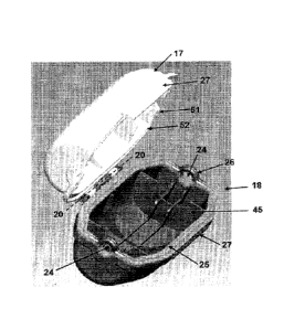
[00321 In the accompanying drawings there is schematically depicted a cover 10
to sealingly
enclose a plug assembly 11 of an electric lead or the like. The electrical
lead includes a plug
assembly 11 having a first lead portion 12 extending to a female plug portion
13, and a second
lead portion 14 extending to a male plug portion 15. The lead and plug
portions 12, 13, 14, 15
forming a plug assembly 11 and are typically electrical leads and plugs.
[0033] The cover 10 includes a hollow body assembly 16 including a first body
17 and a
second body 18. The bodies 17 and 18 extending from a base 50 to a rim 51. The
rim 51 having
a groove 52 or the like being connected by a hinge or hinges 19 so as to be
angularly movable
relative to each other about an axis 20. The axis 20 being substantially
parallel to the
longitudinal length of the cover 10 and bodies 17, 18. The bodies 17 and 18
are typically
concave in shape so that in the closed position (see Figure 10) they provide a
closed chamber 9
within which the plug assembly 11 is located. In a preferred form, one or more
of the bodies 17,
18 are transparent so that a user can see into the closed chamber 9. This will
be of assistance as
some plugs 13, 14 and the leads 15, 16 include a light or lights (not shown)
or other visual
CA 02836185 2013-11-14
WO 2012/167326 PCT/AU2012/000666
indicators to indicate to a user when electricity is flowing through the leads
15, 16. The
transparency allows a user to note this light (or visual indication) and that
leads 15, 16 are
connected. Any separation of the plugs 12, 13 will also be noted. The bodies
17, 18 may also be
of different colours and/or different shapes. For example, a rectangular or
triangular cross
section or the like may be utilised. The bodies 17, 18 when sealed will also
provide sufficient
floatation so that the cover 10 will float in a liquid while providing a water
tight seal to the
chamber 9. The cover 10 would be manufactured of a strong solid material, such
as hardened
plastic or the like, so that a user or object could place weight an the cover
10 inhibiting the cover
cracking, breaking or buckling.
100341 Each body 17 and 18 has longitudinally extending side walls 21 and end
walls 22. The
side walls 21 extend generally parallel to the longitudinal axis 23 of the
cover 10. Each of the
end walls 22 is provided with a recess or socket 24 providing a space to
receive a lead portion 12
and 14. The size and shape of the socket 24 can vary for different regions of
the world. The
cover 10 will accommodate different electrical standards. One or more ribs 45
can be included
in the bodies 17, 18 substantially perpendicular and/or parallel to the
longitudinal axis to provide
strength to the cover bodies 17, 18.
10035) One of the bodies 17, 18 has seals 25 of resilient material adapted to
sealingly engage
the other body, while the sockets 24 of the body 17 has seal ends 26 to engage
the lead portions
12 and 14. The seals 25, 26 are preferably the one seal and formed of a single
unitary piece of
resilient material to completely surround the chamber 9 and provide a water
tight seal. See for
example Figure 13. The seals 25, 26 have portions, inserts, straps, plugs or
the like (see Figure
13) at each end to fit into the sockets 24. An aperture of various sizes such
as 6.5 mm x 6.5 mm,
6.5 mm x 8.5 mm, 8.5 mm x 8.5 mm, 6.5 mm x 9.5 mm or 9.5 mm x 9.5 mm, for
example is
formed depending upon lead size.
CA 02836185 2013-11-14
WO 2012/167326 PCT/AU2012/000666
6
[0036] In the closed position, the bodies 17 and 18 are sealingly connected by
the seal 25, with
the seal ends 26 sealingly engaging the lead portions 12 and 14 so that the
plug assembly 11 is
sealingly contained within the cover 10. This arrangement also inhibits the
leads 12, 14 from
separating apart from each other.
[0037] A catch or lock 27 is provided to lock the body 18 to the body 17. The
catch 17 in one
embodiment is pivotable about an axis 28 that is parallel to the axes 20 and
23. The catch 27
could however be snap locking. A further locking device (not shown) could be
utilised to allow
the catch 27 to be padlocked closed to prevent the cover 10 from being opened
by an unwanted
person. The catch 27 can also include a pivotable bar (not shown) to be locked
into a hooked
protrusion (not shown) on the adjacent body.
[0038] Preferably the seal ends 26 frictionally engage the lead portions 12
and 14 to prevent
separation of the female plug portion 13 from the male plug portion 15 with
the cover 10. In a
further embodiment, the end walls 22 are located so as to be adjacent the end
extremities 29 to
again prevent separation of the female and male plug portions 13, 15.
[0039] As shown in Figures 12 and 13 the seal ends 26 could also include an
upper portion 100
and a lower portion 102 which connect together to seal about the lead portions
12 or 14 at one or
more end walls 22. The upper portion 100 having a flap 110 with a hole 112 to
be received by a
corresponding protrusion 114 on the lower portion 102 of the other body or
vice versa (as in
Figure 13). The portions 100, 102 can be connected by a hinge 115 or the like
and also could
include a step and groove 116 to assist fitting and sealing as shown in Figure
13. This
arrangement allows access for the leads 12, 14 and a complete water tight seal
of the cover 10. '
This arrangement will also prevent the leads 12, 14 from moving apart
separating the plug
assembly 11.
CA 02836185 2013-11-14
WO 2012/167326
PCT/AU2012/000666
7
[0040] The cover 10 could also include a strap or the like (not shown) to
allow the cover 10 to
be hung over a surface or the like. A plug (not shown) could also be included
within the cover
in case there is only one lead.
[0041] The cover 10 is adapted to meet standards and watt-amps throughout the
world and is
adjustable to the local circumstances. Accordingly, in at least a preferred
embodiment, a cover
10 for a plug assembly 11 is provided that provides a water tight seal in any
environment. Each
rim can include one or more grooves or channels to receive said seal.
[0042] Although the invention has been described with reference to specific
examples, it will
be appreciated by those skilled in the art that the invention may be embodied
in many other
forms.