Note: Descriptions are shown in the official language in which they were submitted.
CA 02836427 2014-05-22
ADJUSTABLE HOLD-DOWN ASSEMBLY FOR A SICKLE CUTTER SYSTEM
This invention relates to an adjustable hold-down guard assembly for
the sickle knife of a crop cutting apparatus such as a swather or combine
harvester.
BACKGROUND OF THE INVENTION
The present invention relates generally to a crop cutting device
comprising a plurality of knife guards arranged to be mounted in spaced
relation
along a cutter bar and projecting forwardly therefrom in transverse alignment;
each
of the guards having an upwardly facing ledger surface with opposed side edges
thereof arranged to provide first and second shearing edges; a sickle bar
mounted in
transversely extending position and being driven for reciprocating movement
relative
to the knife guards; the sickle bar having a plurality of knife blades mounted
thereon
for movement therewith; each of the knife blades having a cutting surface for
passing across the ledger surface of the knife guards and an opposed surface;
each
of the knife blades having two side cutting edges which are beveled from the
opposed surface to the cutting surface to cooperate with the shearing edges of
the
knife guards; the sickle bar being driven to carry the knife blades back and
forth
between the knife guards.
It is well known that many sickle knives of this general type include a
conventional or pointed guard where the guard is formed as an integral element
which includes a base piece attached to the cutter bar and defining the ledger
surface and a nose piece projecting forwardly from the ledger surface in front
of the
front edge of the blade which is generally pointed at a leading end so as to
separate
the crop to each side of the guard. This nose piece also stands up in front of
the
CA 02836427 2014-05-22
2
ledger surface to protect the front edge of the blade and includes a
rearwardly
extending shelf over the ledger surface which forms a slot with the ledger
surface
through which the blade passes. Guards of this type include separate hold down
members between the guards which apply downward pressure on the cutter bar to
press the blades against the ledger surface.
Pointed guards generally feature a point with a cut slot that the sickle
blades reciprocate in and out of. Various types of hold-down arrangement are
used
to apply pressure to the sickle to keep its shearing surface in close contact
with the
guard ledger as cutting occurs. Usually these are located between the guard
point or
at the rear edge of the sickles. Most are sheet metal and feature easy
adjustment
using a hammer or a simple single point threaded adjustment. By keeping the
hold-
downs separate from the guards fewer hold-downs than points may be used to
reduce the cost and number of adjustments required. Pointed guards have found
much favor in easier cutting conditions due to the ease of adjustment and
superior
performance.
Another form of guard is known as a stub guard which is formed in two
separate pieces including a base piece which carries the ledger surface and a
top
piece which extends over the ledger surface. The pieces are separate and
separately adjustable relative to the cutter bar so that the top piece can
apply
pressure onto the blade to press it onto the ledger surface. The pieces
terminate at a
front edge which is just behind the front edge of the blade so that the front
edge of
the blade is presented to the crop.
CA 02836427 2014-05-22
3
In tough cutting, stub or no-clog guards have found the most favor.
Stub guards use a separate top and bottom guard pieces that spaced slightly
more
than one sickle blade thickness apart create a slot for the blade to operate
in. The
front edge of the blade protrudes slightly past the front tip of the two
guards. This
feature is what originally gave stub-guards their non-clogging self-cleaning
action. A
major improvement in stub guard technology was made when fully adjustable top
hold-down assemblies were introduced. These arrangements allowed the gap to be
controlled much more precisely than previously so that the shearing surface of
the
blade was kept in close contact with the guard ledger surface. This
adjustability
allows the stub top piece to act as a much more effective hold-down than the
hold-
downs found on regular pointed guard systems.
The pointed guard has an advantage of presenting a point to the
incoming crop so that crop is effectively divided around it. This is
especially
advantageous when the sickle blade is at or near the end or start of each
stroke and
a front edge of each blade, which is typically a blunt front edge of a width
of the
order of 0.5 inch, is hidden partially or entirely within the guard slot.
Since the sickle
bar velocity is lowest at or near the end or start of each stroke this gives
the pointed
guard a considerable advantage over the stub guard for most crops.
The guards can be formed as single elements separately mounted on
the guard bar or as double or triple elements connected together side by side
for
common mounting and common adjustment relative to the guard bar. There is no
reason why more elements might be included but this is not typical.
CA 02836427 2014-05-22
4
In some cases the arrangement is of the double sickle type where
each sickle bar is essentially half the length of the cutter bar and the
cutter bars
reciprocate in opposite phase to minimize vibrating mass and vibrations.
Usually the
sickle bars are timed so that they move in opposite directions so that
vibrations
induced into the cutter bar assembly are minimized.
The sickle knife cutting system has been widely accepted as the most
power efficient system due to the shearing action. However due to speed
restrictions of generally less than 5 to 8 mph ground speed, other systems
such as
rotating flail systems have come into use since these can be operated at much
lo higher ground speed of up to 14 mph while maintaining a high cutting
efficiency.
Such rotary systems have however much higher power usage, are limited in width
and provide crop handling difficulties for forming effective swaths for drying
of the
crop.
Cutting crops such as soy beans where the bean pods can be located
closely adjacent the ground typically requires low ground speeds of around 4
to 5
mph to ensure that the crop is cut and fed into the combine harvester without
too
much loss of the pods. Pods can be lost if the cutting action causes some or
too
many of the lowest pods to be left at the stubble or broken up by the cutting
action, It
would be highly desirable to increase cutting speed above the typical range of
4 to 5
mph so as to increase this to or above 6 mph.
Cutting crops such as hay or forage crops such as alfalfa or grasses
typically allows higher ground speeds of up to 10 mph since the crop is more
CA 02836427 2014-05-22
resistant to a poor or inefficient cutting action. It would be highly
desirable to
increase cutting speed above the typical range of up to 10 mph so as to
increase
this to or above 12 or even 14 mph.
The term "sickle bar" as used herein is intended to refer generally to a
5 structure which supports all of the knife blades at the spaced positions
along its
length and is not intended to be limited to a single continuous element
extending
along the whole length of the structure. Thus the bar may be formed of
different
elements at different parts of the length and may include pieces below and
above
the blades.
SUMMARY OF THE INVENTION
According to one aspect of the invention there is provided a sickle
cutting apparatus comprising:
a plurality of stationary knife guards arranged to be mounted along a
cutter bar;
a sickle bar mounted in transversely extending position and arranged
to be driven for reciprocating movement relative to the knife guards;
the sickle bar having a plurality of knife blades mounted thereon for
movement therewith;
each of the knife blades having a cutting surface for passing across the
knife guards;
each of the knife blades having on first and second sides first and
second side cutting edges;
CA 02836427 2014-05-22
6
each knife guard comprising:
a base portion arranged to be mounted on the cutter bar;
at least one guard finger mounted on the base portion so that
the guard fingers are arranged to be mounted in a row along the cutter bar;
each guard finger having an upwardly facing ledger surface with
opposed side edges thereof arranged to provide first and second shearing edges
which cooperate with the side cutting edges of the knife blades;
and a plurality of hold-down members arranged to be mounted along
the cutter bar;
each hold-down member comprising a base mounting member
arranged to be attached to the cutter bar;
each hold-down member comprising two hold-down fingers thereon
carried on the base mounting member arranged to be at positions spaced
longitudinally of the cutter bar so as to be cantilevered forwardly from the
cutter bar
to a position of a front tip of each hold-down finger located at a settable
spacing in
front of the sickle bar above the ledger surface of a respective one of the
guard
fingers;
wherein each of the base mounting members is arranged to be
attached to the cutter bar by at least two threaded fasteners passing through
the
cutter bar and through the base mounting member which can be adjusted to
tighten
the base mounting member onto the cutter bar;
CA 02836427 2014-05-22
7
the threaded fasteners having axes of the threaded fasteners lying at
spaced positions along an imaginary line longitudinally of the cutter bar;
wherein each of the hold-down fingers is arranged to be adjustable on
the cutter bar to change the settable spacing thereof;
wherein each of the hold-down fingers is pivotal relative to the cutter
bar about a fulcrum extending longitudinally of the cutter bar and located at
a
position forwardly of the imaginary line;
wherein each of the two hold-down fingers includes a respective
adjustment screw for individual adjustment by extension of the adjustment
screw
located at a position rearwardly of the imaginary line;
and wherein the base mounting member connects the two hold-down
fingers and defines a bridge between the two hold-down fingers which is shaped
to
provide lateral strength and to be sufficiently flexible in torsion to provide
the
individual adjustments.
Preferably the fulcrum and the adjustment screws are located relative
to the imaginary line such that the hold-down fingers are adjustable by
extension of
the respective adjustment screw to reduce the settable spacing without
adjustment
of the threaded fasteners.
Preferably the fulcrum is arranged at a position spaced slightly forward
of the imaginary line by a distance less than a radius of the threaded
fasteners such
that there is slight sliding movement of the fulcrum rearwardly when the
adjustment
screw is extended.
CA 02836427 2014-05-22
8
Preferably the fulcrum comprises an apex of a rib along the base
mounting member arranged longitudinally of the cutter bar.
Preferably the adjustment screw is behind the threaded fasteners out
of the crop flow which allows the adjustment screw to comprise a bolt with a
head
projecting upwardly from a top surface of the hold-down member.
Preferably the hold-down member including the hold-down fingers and
the base mounting member comprises an integral member with a bottom surface
including the fulcrum arranged to directly contact an upper surface of the
cutter bar
with no intervening elements.
Preferably the bridge does not include a trash bar so that the fingers
are divided all the way back to a position behind the sickle bar.
Preferably the threaded fasteners each include a shoulder engaging an
upper surface of the hold-down member and the upper surface includes a
downwardly curved surface at least rearward of the imaginary line to allow
rotation of
the hold-down member on the shoulder during the extension of the adjustment
screw. The relief to the rear of the nuts is more important when adjusting the
hold-
down finger down. Also the direction of the curved surface is important.
However in
most cases the whole of the undersurface is arcuately curved on both sides of
the
imaginary line.
According to another important aspect of the invention there is
provided a sickle cutting apparatus comprising:
CA 02836427 2014-05-22
9
a plurality of stationary knife guards arranged to be mounted along a
cutter bar;
a sickle bar mounted in transversely extending position and arranged
to be driven for reciprocating movement relative to the knife guards;
the sickle bar having a plurality of knife blades mounted thereon for
movement therewith;
each of the knife blades having a cutting surface for passing across the
knife guards;
each of the knife blades having on first and second sides first and
second side cutting edges;
each knife guard comprising:
a base portion arranged to be mounted on the cutter bar;
at least one guard finger mounted on the base portion;
each guard finger having an upwardly facing ledger surface with
opposed side edges thereof arranged to provide first and second shearing edges
which cooperate with the side cutting edges of the knife blades;
the guard fingers being arranged to be mounted at a first
equidistant spacing in a row along the cutter bar;
the guard fingers defining first and second sets of guard fingers
arranged to be mounted alternately along the cutter bar so that each guard
finger of
the first set is located between respective guard fingers of the second set;
CA 02836427 2014-05-22
and a plurality of hold-down members arranged to be mounted along
the cutter bar;
each hold-down member comprising at least one hold-down finger
thereon arranged to extend forwardly from the cutter bar to a position
adjacent the
5 knife blades in front of the sickle bar;
the hold-down fingers being arranged to be mounted at a second
equidistant spacing in a row along the cutter bar;
wherein the second equidistant spacing of the hold-down fingers is
double that of the first equidistant spacing of the guard fingers;
10 each hold-
down finger being arranged to be located in alignment with
and at a spacing above a respective one of the second set of guard fingers for
holding down a respective one of the knife blades onto the ledger surface of
the
respective one of the second set of guard fingers.
Preferably the guard fingers of the second set each include no element
over the knife blade on the ledger surface thereof so that the knife blade on
the
ledger surface thereof is held down only by the respective guard finger and
the
guard fingers of the first set each include no element over the knife blade on
the
ledger surface thereof so that the knife blade on the ledger surface thereof
is not
held down.
Preferably a length and width of the ledger surfaces of the first set of
guard fingers is equal to a length and width of the ledger surfaces of the
second set
of guard fingers.
CA 02836427 2014-05-22
11
In one arrangement each of the guard fingers comprises a pointed
guard finger with a pointed front tip thereof in front of a front tip of the
knife blades
including an upstanding transverse shoulder at a front edge of the ledger
surface.
Preferably there is provided a cutting system including a first plurality
of first stationary knife guards each comprising a stub guard finger with a
front tip
thereof behind a front tip of the knife blades and a second plurality of
second
stationary knife guards each comprising a pointed guard finger with a pointed
front
tip thereof in front of a front tip of the knife blades, the first and second
stationary
knife guards being arranged such that a user can select either the first
stationary
knife guards or the second stationary knife guards to be mounted on the cutter
bar,
the first stationary knife guards, the second stationary knife guards and the
hold
down members are arranged such that the hold down members cooperate with the
first stationary knife guards when selected and with the stationary knife
guards when
selected.
Preferably the spacing of the hold-down fingers above the respective
one of the second set of guard fingers is adjustable by an adjustment screw at
the
cutter bar which can be preferably operated independently of the other hold-
down
fingers.
Preferably the plurality of hold-down members comprises a plurality of
first hold-down members and a plurality of second hold-down members arranged
to
be mounted alternately along the cutter bar, the first hold-down members
having a
CA 02836427 2014-05-22
12
single one of the hold-down fingers thereon and the second hold-down members
having two of the hold-down fingers thereon.
Preferably each knife guard has three fingers mounted on the base
portion and wherein each of the first and second hold-down members is
associated
with a respective one of the knife guards and is arranged to be mounted on the
cutter bar commonly therewith.
Preferably a center line spacing between each guard finger and the
next is equal to 2.0 inches. However the arrangement can be used with other
center
line spacings such as the conventional 3 inch spacing.
Preferably a stroke length of the reciprocating movement of the sickle
bar is equal to the center line spacing between each guard finger and the next
so
that each knife blade is moved between a position aligned with a guard finger
of the
first set and a position aligned with a guard finger of the second set.
Preferably the knife blades are arranged as first and second blades of
a connected pair and the reciprocating movement is arranged such that each
connected pair is moved in the reciprocating movement between a first position
in
which the first blade of the pair is aligned with a respective hold down
finger and a
second position in which the second blade of the pair is aligned with the
respective
hold down finger.
Preferably at least some of the hold-down members include a hold
down ledge arranged above a rear edge of a base of the knife blade.
CA 02836427 2014-05-22
13
BRIEF DESCRIPTION OF THE DRAWINGS
Figure 1 is a top plan view of a part of header showing a portion of the
sickle knife according to a first embodiment of the present invention using a
pointed
guard.
Figure 2 is an isometric view of the part of the header of Figure 1.
Figure 3 is a cross-sectional view along the lines 3-3 of Figure 1.
Figure 4 is a cross-sectional view along the lines 4-4 of Figure 1.
Figure 5 is bottom plan view of a hold-down member for use in the
sickle knife of Figure 1.
Figure 6 is a cross-sectional view along the lines 6-6 of Figure 1.
Figure 7 is a top plan view of a part of header showing a portion of the
sickle knife according to a first embodiment of the present invention using a
stub
guard.
Figure 8 is a cross-sectional view along the lines 8-8 of Figure 7.
Figure 9 is a top plan view of an alternative arrangement of guard
member where alternate ones of the guard fingers and pointed guard fingers
intermediate two stub guard fingers.
DETAILED DESCRIPTION
In Figures 1 and 2 is shown a first embodiment of a crop cutting device
generally indicated at 10. Only a part of the complete machine is shown since
the
remainder of the machine may vary widely depending upon requirements and since
the construction is of course well known to a person skilled in the art. In
this
i
CA 02836427 2014-05-22
14
embodiment as shown, there is a frame generally indicated at 11 which forms
only
one part of the total frame structure that is the part of the frame that is
relevant to the
present invention.
The cutting device 10 further includes a cutter bar 12 attached to the
frame structure 11. Thus the frame structure 11 in the part as shown comprises
a
guard bar 13 to which is attached a plurality of knife guards 14. The guard
bar 13 is
attached to the frame structure which supports the guard bar in fixed position
across
the front edge of the frame for a cutting action of the crop cutting device on
the
standing crop.
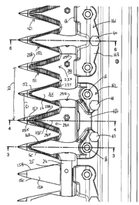
Each knife guard 14 includes three guard fingers 14A arranged ma
triple guard but guards can be arranged with a single finger, pair of fingers
or triples.
As shown the guard bar forms a triple guard construction with three fingers
where a
series of such guards are mounted on the guard bar 13 at spaced positions
along
the length of the guard bar.
The knife guards can comprise a stub guard as shown in Figure 7 but
shown in Figures 1 and 2 each guard finger 14A comprises a pointed guard which
includes a lower portion 15 and an upper portion or hold-down finger 16. These
two
portions are mounted on the guard bar 13 by a mounting arrangement 17
including
bolts 18. The mounting arrangement thus attaches a rear end 19 of the lower
portion
15 rigidly on the underside of the bar 13 so that the fingers of the guard
project
forwardly from the bar to a front nose 20. Similarly the hold-down finger 16
is
1
CA 02836427 2014-05-22
mounted on the guard bar 13 by an adjustment plate 21 attached onto the same
bolts 18. Each hold-down finger 16 extends forwardly to a nose 22.
In the embodiment shown in Figures 7 and 8 the guards are stub
guards so that the noses 20, 22 substantially overlie one another and confine
5 between them the blades 23 of the sickle bar or knife back 24.
Each pair of guards thus includes two guard elements each defined by
an upper portion or hold-down finger 16 and a lower portion or guard finger 15
and
the guard elements are shown in FIG. 1. A front crop guide bar or trash bar
can be
also provided but in the embodiment as shown no such trash bar is included so
that
3.0 the guard fingers 15 are separated and unconnected to each other all
the way back
to the sickle bar 24. In front of the rear end 19 of the lower portion 15 is
provided a
channel 25 within which the sickle bar or knife back 24 is mounted for
reciprocating
movement.
The trash bar may form a continuous bar member extending along the
15 lower guard portion 15 in front of the bar 24 to prevent any crop
reaching that area.
. However the trash bar may be formed by any part of the system which prevents
the
crop from moving rearwardly beyond the rear end of the cutting edges of the
blades.
There may be a single sickle bar 24 driven from one end or in some
cases there are two sickle bars driven from opposite ends and meeting in the
middle. The sickle bar or bars 24 are driven by the reciprocating drive motor
(not
shown but conventional) such that the bar 24 reciprocates back and forth.
CA 02836427 2014-05-22
16
In some cases the bar 24 reciprocates by a distance Si equal to the
space between the nose of one guard fingers 15 and that of the next along the
guard
bar 13 so that the blades 23 reciprocate from a position with the center line
of the
knife 23 aligned with the center line of the first guard finger to a position
aligned with
the next guard finger and back to the first. In other cases, the reciprocation
stroke
may be as shown at 52 a multiple of, typically double, the distance between
the
guards so that the knife moves from a first guard finger across a second to a
third
and back to the first. This arrangement reduces the available reciprocation
rate due
to increased acceleration forces but reduces the number of reversals.
Each sickle bar comprises the support bar member 24 and the plurality
of blades indicated at 23. As shown the blades are formed in pairs mounted on
a
common base, but individual blades may be provided or in some cases the blades
may have more than two on the same base.
Each of the blades forms a generally triangular-shaped member which
has a rear end or base 23A bolted to the bar and converges from the rear end
to a
front end 23B. Each of the blades has a top surface 23D and a bottom surface
23E.
Each of the blades has a side edge 23F and a second side edge 23G. The sides
edges are beveled from the top surface down to the bottom surface 23E so that
a
sharp edge is formed at the bottom surface at each of the side edges. The
blades
are also serrated at each cutting edge with grooves extending parallel to the
bars 24
that is at right angles to a center line 23H.
CA 02836427 2014-05-22
17
The hold-down finger 16 acts to hold the blades downwardly into
engagement with the top ledger surface 15A of the bottom portion 15. The
bottom
portion 15 has two side edges of the ledger surface 15A as best shown in FIG.
2
with those side edges 15B and 15C acting as side edges of the ledger surface
15A.
Thus the cutting action of the blades occurs between the ledger 15A and the
bottom
surface 23E of the blade as the blade reciprocates from its position at one of
the
guards to its position at the next adjacent one of the guards. In this cutting
action,
therefore, the side edge of the blade moves across the space between the
guards
and enters onto the ledger surface of the next guard in a cutting action
between the
bottom surface of the blade and the top surface of the guard which are
immediately
adjacent and generally in contact or at least closely adjacent to provide a
shearing
action on the crop.
In these guards, the hold-down finger 16 acts to prevent the pair of
blades 23A from moving away from the ledger surface 15A by applying pressure
to
that upper surface 23D of the blade and holding the blade in contact with or
closely
adjacent the ledger surface 15A of the bottom portion where the cutting action
occurs. The hold-down finger 16 therefore as shown in Figure 1 has side
surfaces
16B and 16C of the bottom surface 16A which are narrower than the ledger
surface
15A of the bottom portion 15.
The mounting and adjustment arrangements for the bottom portion 15
and the hold-down finger 16 can vary in accordance with a number of different
designs readily available to a person skilled in the art. It suffice to say
that the hold-
CA 02836427 2014-05-22
18
down portion 16 is adjustable so that the gap between the bottom surface of
the
hold-down portion and the ledger surface of the bottom portion 15 can be
adjusted to
allow the sliding action of the blades while holding the blades in the
required
position.
The disclosures of the following documents of the present Applicants
may be referred to for details of the construction not provided herein. These
show
various conventional details of the sickle knife system which can be used in
the
arrangement herein but are not described as they are known to persons skilled
in
the art.
US Patent 7,328,565 (Snider) issued February 12 2008;
U.S. Patent 4,894,979 (Lohrentz) issued Jan. 23, 1990
U.S. Patent 4,909,026 (Molzahn) issued Mar. 20, 1990.
U.S. Patent 6,962,040 (Talbot) issued Nov 8, 2005.
US Published application 2013/0192188 (Talbot) published August 1
2013.
In Figure 1, a drive for knife bar 24 can comprise any suitable drive
system known to persons skilled in this art of a type which can generate a
stroke S1
of 2 inches at a drive rate of typically 918 rpm. The system can also be
arranged in
an alternative embodiment to drive the stroke S2 of 4 inches in which case the
reciprocation rate may be lower. The drive system includes an input from a
ground
CA 02836427 2014-05-22
19
speed indicator which allows automatic adjusting of the stroke rate of the
drive
system in dependence on ground speed.
Typically each of the knife blades is generally triangular in shape with
straight side edges 23F, 23G. However other shapes of the side edges 23F, 23G
in
plan such as convex or concave can be used. Thus the side edges 23F, 23G
converge to the front apex 23K at an angle of the order of 60 degrees to the
direction of reciprocating movement. The two converging side cutting edges
23F,
23G are beveled from the upper surface 23D to the bottom cutting surface 23E
to
cooperate with the shearing edges of the knife guards. In addition the beveled
side
edges are serrated with grooves running in a direction longitudinal to the
reciprocating direction. In order to maximize the cutting action, the length
of the
cutting edge is substantially the maximum length extending from the sickle bar
24 at
the rear to a position close to the front apex 23K of the blade.
At the position in the stroke shown in Figure 1 where the center line C
of the knife blades is aligned with the center line Cl of the guard fingers,
the side
cutting edges of the knife blades 23F, 23G substantially directly overlie the
side
edges 15B, 15C of the ledger surface 15A.
Each knife blade has a front point portion in front of the side cutting
edges 23F, 23G which front point portion has side edges converging to the
front
apex 23K, where the apex and the side edges of the front point portion are
shaped
and arranged such that crop material engaging the front point portion, as the
point
portion is moved forwardly in the crop, is shed to one or other side of the
front point
CA 02836427 2014-05-22
portion for cutting by the side cutting edges and is not pushed forwardly by
the front
point portion 23X.
Thus the preferred construction provides a center line spacing between
each knife blade and the next is of the order of or equal to 2.0 inches, the
radius of
5 curvature of the front pointed portion at the apex is less than 0.25 inch
and the side
edges of the front portion are arranged relative to a center line of the blade
at an
angle of the order of 20 degrees.
As shown in Figure 1, the width between the centers of the guards is
indicated at Sl. This can be the same as the length of the cutting stroke so
that the
3.0 blades move from a position aligned with the center line of one guard
finger to that of
the next. However in some embodiments the stroke may be a multiple of the
distance D, typically twice, so that the blades move from the first guard
finger to the
third crossing the second. The reversal of the reciprocating action at the
guard
center line ensure that the blades are stationary and therefore carrying out
no cutting
15 when they are overlying the guard and not at an intermediate location.
The increase
of the stroke length to a multiple of the finger reduces the number of times
the
blades are stationary but requires a reduced stroke rate due to the increased
forces
on the drives system.
This distance Si is preferably of the order of 2.0 inches. The fore-aft
20 length of a blade has traditionally been in the order of 1.75 inches
from the front of
the trash bar to the tip of the section, or 2.2 inches from the front edge of
the knife
back to the tip of the section.
CA 02836427 2014-05-22
21
It is common practice for sickle blades to have the front edge as a
transverse straight edge in the order of 0.6 inches wide. The wide tip has the
potential for running down crop, thus leaving long uncut stems. In the present
invention the blade is designed with a pointed tip or front apex 23K, thus
eliminating
the problem.
The guard fingers have the upwardly facing ledger surface 15A with
opposed side edges arranged to provide first and second shearing edges. The
guard fingers have a downwardly facing ground engaging surface 156 shaped and
arranged to provide protection for stone engagement as the fingers slide over
the
ground. That is each finger has sufficient strength to avoid breakage when
impacting stones and obstacles causing the cutter bar to rise if the impact is
sufficient and extends over sufficient number of guard fingers to provide the
lifting
action. This shape of the ground engaging surface is well known to persons
skilled
in the art and includes a longitudinal rib which is generally triangular in
cross-section
on the underside of the upper part containing the ledger surface. The base of
the rib
thus forms an apex which runs over the ground to prevent upward forces from
snapping the guard finger at the ledger surface.
An upstanding transverse shoulder 157 is provided at a front edge of
the ledger surface 15A and extends upwardly to a top surface 158 of the finger
where the shoulder terminates. Thus there is no tang of conventional shape,
that is
no portion of the guard extends rearwardly over the ledger surface 15A from
the
shoulder 157. Above the ledger surface 15A therefore the knife blades of
alternate
i
CA 02836427 2014-05-22
22
ones of the guard fingers are free from confinement by a conventional tang as
used
in a conventional pointed guard or by a cooperating upper guard finger of the
type
used in a stub guard.
A tip portion 159 in front of the ledger surface extends forwardly from
the shoulder 157 and defines a forwardmost generally pointed tip 160 for
engaging
crop in front of the ledger surface 15A.
Each knife guard thus includes a base portion 19 mounted on the
cutter bar 13 by the two longitudinally spaced bolts 18 each of which has a
head 18A
engaging a bottom face of the base portion 19. The knife guard further
includes
three equally spaced guard fingers 15 mounted on the base portion 19 so as to
be
commonly mounted on the cutter bar at a first equidistant spacing in a row
along the
cutter bar 13.
The guard fingers are arranged also to define a first set and second set
of guard fingers arranged alternately along the cutter bar so that each guard
finger
151 of the first set is located between respective guard fingers 152 of the
second
set. Thus each triple guard defined by three fingers has either two fingers
151 either
side of a finger 152 or has two fingers 152 either side of a finger 151. All
of the
fingers 151 and 152 are identical but as explained hereinafter, the fingers
151 are
left open and have no corresponding hold-down finger, sometimes called an
upper
guard, whereas each of the fingers 152 cooperates with a respective one of the
hold-down fingers 16.
,
CA 02836427 2014-05-22
23
Thus there are provided a plurality of hold-down members 161 and 162
mounted along the cutter bar. Each hold-down member 161, 162 has at least one
hold-down finger 16 thereon extending forwardly from the cutter bar 13 to a
position
adjacent the knife blades at the ledger surfaces 15A in front of the sickle
bar 24.
Thus the hold-down members 161 have a single central finger 16
mounted on a mounting base 163 and the hold-down members 162 have two
separate spaced fingers 16 mounted on a mounting base 164. These are arranged
on the mounting bases so that the hold-down fingers are arranged in a row at a
second equidistant spacing along the cutter bar where the second equidistant
spacing of the hold-down fingers 16 is double that of the first equidistant
spacing of
the guard fingers 15. The result of this is that the hold-down fingers 16 are
arranged
on the alternate guard fingers 152 leaving the guard fingers 151 open and free
from
a hold-down. Thus each hold-down finger 16 located in alignment with and at a
spacing above a respective one of the second set 152 of guard fingers for
holding
down a respective one of the knife blades 23A onto the ledger surface 15A of
the
respective one of the second set 152 of guard fingers.
As explained previously the guard fingers 151 and 152 are pointed
guards but have no conventional tang over the knife blade on the ledger
surface
thereof which would typically define a slot so that the knife blade 23A on the
ledger
surface 15A thereof is held down only by the respective guard finger 16.
Thus the guard fingers 151 of the first set each include no element at
all, that is not a tang and not a hold -down over the knife blade on the
ledger surface
CA 02836427 2014-05-22
24
15A so that the knife blade 23A on the ledger surface 15A of the fingers 151
is not
held down at all except for the residual effect of the hold-down finger 16
over the
adjacent guard finger 152.
The guard fingers 151 and 152 are identical in other respects so that
particularly the length and width of the ledger surfaces 15A of the guard
fingers 151
is equal to a length and width of the ledger surfaces of the second set of
guard
fingers.
In Figures 1 to 6, each of the guard fingers comprises a pointed guard
finger with a pointed front tip 159, 160 in front of a front tip 23B of the
knife blades
23A. This pointed guard includes the upstanding transverse shoulder 157 at a
front
edge of the ledger surface 15A. The spacing of the tip 22 of the hold-down
fingers
16 above the respective one of the second set of guard fingers 152 is
adjustable by
an adjustment screw 40, 41, 42 at the cutter bar 13 independently of the other
hold-
down fingers 16.
Each triple knife guard is associated with a respective one of the hold-
down members 161, 162 and is mounted on the cutter bar 13 commonly therewith
by the pair of bolts 18. The bolts 18 are spaced apart along the cutter bar so
as to
engage into holes through the cutter bar aligned with holes in the base 163 of
the
hold-down member 161 and with corresponding holes in the base member 19 of the
guard member. Similarly the hold-down member 162 is bolted by two bolts 18
onto
the cutter bar 13 in association with the underlying guard member.
CA 02836427 2014-05-22
As shown in Figure 3, tightening of the two bolts 18 acts to clamp the
upper surface of the base 19 onto the underside of the cutter bar 13 and to
clamp a
bottom surface 44 of the base member 164 of the double hold-down member 162
onto the top surface of the cutter bar 13. The same arrangement is shown in
Figure
5 6 respect of the hold-down member 161.
As best shown in Figure 1, the knife blades 23X and 23Y are arranged
as first and second blades of a connected pair 23Z mounted on a common base
carried on the sickle bar 24. These pairs are separately mounted on the bar 24
by a
pair of bolts 23P and 23Q so that each pair of blades can be removed
independently
10 of the others for replacement. The reciprocating movement of the bar 24
is arranged
such the blades 23X and 23Y of the connected pair 23Z are moved in the
reciprocating movement between a first position shown in Figure 1 in which the
first
blade 23Y is aligned with the specific hold-down finger 16X and a second
position
(not shown) in which the second blade 23Y of the connected pair 23Z is aligned
with
15 the hold-down finger 16X. Thus the finger 16X is associated with the
connected pair
23Z and does not cooperate with any others of the blade pairs. This situation
is of
course repeated along the bar 24 by each of the fingers 16 and the pairs. In
this
way, in the event that a replacement blade pair is inserted into position on
the bar
24, for example due to a breakage, it sits alongside other pairs which are
older and
20 hence are more worn and therefore thinner. Each finger 16, when adjusted as
explained hereinafter to set the spacing with the respective guard finger 15,
is
CA 02836427 2014-05-22
26
associated with a respective blade pair and can be set in dependence on the
thickness of that specific pair without any reference to the other blade
pairs.
As shown in Figures 1 and 6 the single hold -down members 161
include the single finger also include a hold-down ledge 46 on each side of
the
single finger projecting forwardly from the base portion 163 to a position
above a
rear edge of a base of the knife blade. The hold-down ledge 46 covers only a
narrow strip at the rear of the base of the blade so as to assist in
preventing lifting of
the blade when it is free from the finger 16.
In Figures 1 to 6, the arrangement uses pointed guards with the
pointed portion in front of the tip 23B of the blade. In Figures 7 and 8 the
arrangement uses stub guards 115 with the tip 116 of the guard 115 just behind
the
tip 23B of the blade, as is conventional in stub guards. In both arrangements
the
hold-down fingers 16 have the tip thereof just behind the tip 23B of the
blade.
The stub guards 115 and the pointed guards 15 are arranged such that
a user can select either the stub guards 115 or the pointed guards 15 to be
mounted
on the cutter bar 13 depending on cutting conditions at the choice of the
user. That
is the dimensions of the base portion 19 are identical in both cases to match
with the
holes in the cutter bar and with the bolts 18 therein. Thus the user can
select all
stub guards for cutting so that the blade projects beyond the guard and hold-
down
fingers in the conventional cutting action.
Alternatively the user can select all
pointed guards if the cutting conditions and the crop to be cut dictate such
guards.
CA 02836427 2014-05-22
27
In an optional arrangement shown in Figure 9 some of the guard
fingers each comprise a pointed guard finger 215 with a pointed front tip 216
thereof
arranged to liein front of a front tip of the knife blades as explained above,
and some
of the guard fingers arranged intermediate the pointed guard fingers 215
comprise
stub guard fingers 315 with a front tip thereof arranged to be behind a front
tip of the
knife blades as described above. In Figure 9 there is shown a guard having
three
fingers where two of the fingers 215 are pointed guard fingers either side of
a stub
guard finger 315. In order to create and arrangement in which the pointed
guard
fingers alternate with the stub guard fingers there is provided a second guard
not
shown where there are two stub guard fingers wither side of a pointed guard
finger
and the two types are alternated along the cutter bar mounted on the bolts 18.
.
Also the stub guards 115, the pointed guards 15 and the hold-down
members 16 are arranged such that the hold-down members 16 cooperate with the
stub guards 115 when selected and with the pointed guards 15 when selected.
That
is the dimension of the hold-down members is arranged so that they overlie the
ledger surface of both the stub guards when used and with the pointed guards
when
used. Also the pointed guards have no conventional tang so that the ledger
surface
of the pointed guard is presented upwardly to cooperate with the hold-down
finger.
As best shown in Figures 4 and 5, the threaded fasteners or bolts 18
have axes 18X lying at spaced positions along an imaginary line 18Y extending
longitudinally of the cutter bar. The hold-down fingers are adjustable on the
cutter
CA 02836427 2014-05-22
28
bar to change a settable spacing S between the bottom surface 22A at the tip
22
and the ledge surface 15A of the respective guard finger 15.
In order to provide this adjustment, each of the hold-down fingers 16 is
pivotal relative to the cutter bar about a fulcrum 47 defined by an apex of a
rib 48
extending longitudinally of the cutter bar 13. The rib 48 and its fulcrum 47
are
located at a position slightly forwardly of the imaginary line 18Y joining the
axes 18X.
The pivotal movement is carried out by a respective adjustment screw
40, 41, 12 for individual adjustment of each finger 16 by extension of the
adjustment
screw located on the base portion located rearwardly of the imaginary line
18Y, that
is on the opposite side of the fulcrum from the finger. As shown in Figure 5,
each of
the adjustment screws has a respective hole 41A, 42A in the base portion 164
of the
hold-down member 162.
The base mounting member 164 connects the two hold-down fingers
and defines a bridge 165 between the two hold-down fingers which is shaped to
provide lateral strength and to be sufficiently flexible in torsion to provide
individual
adjustments of the two fingers. That is the base member 164 including the
bridge
165 and the fingers extending forwardly therefrom forms an integral casting
where
the portions 166, 167 of the base member 164 connected to the fingers 16 are
rigid
relative to the fingers with the flexibility of the base member 164 being
defined by the
narrower bridge 165.
The fulcrum 47 and the adjustment screws 41, 42 are located relative
to the imaginary line 18Y such that the hold-down fingers 16 are adjustable by
CA 02836427 2014-05-22
29
extension of the respective adjustment screw to reduce the settable spacing S
without adjustment or loosening of the bolts 18. This is obtained by the fact
that the
fulcrum 47 is only slightly forward of the imaginary line and spaced forward
of the
imaginary line by a distance less than a radius of the threaded fasteners,
that is the
fulcrum is behind the edge 18Q f the front of the bolts 18. This adjustment to
reduce the space S as the blades wear obtained by extending the bolts 41, 42
is
obtained because the fulcrum is located such that there is slight sliding
movement of
the fulcrum rearwardly when the adjustment screw 41, 42 is extended.
Each adjustment screw 40, 41 comprises a bolt with a head 40A
projecting upwardly from a top surface of the hold-down member so that the
head
can be grasped by a wrench for application of a significant adjustment force.
As the hold-down member is an integral member with a bottom surface
including the fulcrum directly contacting the upper surface of the cutter bar
13, there
are no intervening elements which need to be adjusted such as adjustment bars
or
shims.
The bolts 18 each include a nut 18N with a shoulder 183 engaging an
upper surface 168 of the hold-down member and the upper surface 18S is arched
or
convexly curved so as to include a curved surface at least rearwardly of the
imaginary line and preferably on both sides of the common line to allow
rotation of
the hold-down member on the shoulder during the extension of the adjustment
screw.
CA 02836427 2014-05-22
The double hold-down members 162 include therefore two adjustment
screws 41, 42 for individual adjustment of the fingers. The single hold-down
members 161 have a single center adjustment screw 40 to adjust the single
finger
so that no flexing of the member 161 is required.
5