Note: Descriptions are shown in the official language in which they were submitted.
81775158
RECHARGEABLE ALKALINE METAL AND ALKALINE EARTH ELECTRODES HAVING
CONTROLLED DENDRITIC GROWTH AND METHODS FOR MAKING AND USING THE SAME
CROSS-REFERENCE TO RELATED APPLICATION
This utility patent application claims priority to co-pending U.S. provisional
patent
serial no. 61/486,946, filed on May 17, 201.1, to co-pending U.S. provisional
patent
application serial no. 61/498,192, filed June 17, 2011, and to co-pending U.S.
provisional
patent application serial no. 61/565,101, filed on November 30, 2011.
BACKGROUND
The use of Lithium metal as an anode to build a rechargeable Lithium cell or
battery
system with the highest anode-specific capacity has long been desired.
However, the
1
CA 2836466 2018-09-24
CA 02836466 2013-11-05
WO 2012/158924 PCT/US2012/038360
growth of Li-metal dendrites gives rise to serious technical barriers for
developing such a
battery. Recently, modified versions of the Li metal battery, such as the
Lithium ion battery,
have been introduced with some success. However, the current modified versions
possess
limitations and inefficiencies that would not arise with a cell that uses
Lithium metal as an
anode.
Typically, a Lithium metal cell includes an anode and a cathode separated by
an
electrically insulating barrier or 'separator' and operationally connected by
an electrolyte
solution. During the charging process, the positively charged lithium ions
move from the
cathode, through the permeable separator, to the anode and reduce into Li
metal. During
discharge, the Li metal is oxidized to positively charged lithium ions which
move from the
anode, through the separator, and onto the cathode, while electrons move
through an
external load from the anode to the cathode, yielding current and providing
power for the
load. During repeated charges and discharges, Lithium dendrites begin to grow
from on the
surface of the anode. Dendritic lithium deposits, sometimes called mossy
lithium,
eventually tear through the separator and reach the cathode causing an
internal short and
rendering the cell inoperable. Lithium dendrite formation is inherently
unavoidable during
the charging and discharging processes of Li-metal cells. Thus, there remains
a need for a
lithium electrode cell system that does not suffer the effects of dendrite
growth while
simultaneously maintaining the cycle ability, ionic conductivity, voltage and
specific
capacity of the cells. The present novel technology addresses these needs.
2
81775158
Summary
In one aspect, there is provided a battery cell, comprising: an electrically
insulating
barrier having an anode-facing side and a cathode-facing side; and
functionalized
nanocarbon particles adhered to the anode-facing side of the electrically
insulating barrier;
wherein the functionalized nanocarbon particles are electrically-conductive;
and wherein
the functionalized nanocarbon particles are functionalized with ionically
associated metal
cations for seeding dendrite growth..
In another aspect, there is provided a battery cell, comprising: an
electrolyte
medium; a cathode in the electrolyte medium; a lithium-containing anode in the
electrolyte
medium and spaced from the cathode; a separator having an anode-facing side
and a
cathode-facing side disposed between the lithium-containing anode and the
cathode, the
separator being electrically insulating and electrolytically permeable; and a
plurality of
functionalized nanocarbon particles operationally connected to the anode-
facing side of the
separator; wherein the plurality of functionalized nanocarbon particles are
functionalized
with ionically-associated metal cations for seeding dendrite growth; and
wherein the
plurality of functionalized nanocarbon particles is electrically-conductive.
In yet another aspect, there is provided a battery cell comprising: an
electrode having
a metal portion, wherein the metal portion comprises lithium, calcium,
magnesium, sodium,
potassium or combinations thereof; an electrolyte permeable membrane; a metal
dendrite
seeding material disposed between the electrode and the electrolyte permeable
membrane;
and at least one dendrite extending from the electrode toward the electrolyte
permeable
membrane, the at least one dendrite extending from the electrode being
combined with at
least one dendrite extending from the metal dendrite seeding material; wherein
the
electrode, the electrolyte permeable membrane, and the metal dendrite seeding
material are
in an electrolyte matrix; and wherein the metal dendrite seeding material
comprises
electrically-conductive metal functionalized carbon nanoparticles that are
functionalized
with ionically-associated metal cations for seeding dendrite growth.
2a
CA 2836466 2018-09-24
CA 02836466 2013-11-05
WO 2012/158924 PCT/US2012/038360
DESCRIPTION OF THE DRAWINGS
FIG. 1 is schematic view of a lithium ion cell according to a first embodiment
of the
present novel technology.
FIG. ZA is a perspective view of the separator of FIG. 1.
FIG. 2B is an exploded view of the separator surface of FIG. 2.
FIG. 3A is a first perspective view of a composite electrode of FIG. 1.
FIG. 3B is a second perspective view of a composite electrode of FIG. 1.
FIG. 3C is a third perspective view of a composite electrode of FIG. 1.
FIG. 3D is a fourth perspective view of a composite electrode of FIG. 1.
FIG. 4 is a perspective view of a second embodiment coin cell implementation
of the
present novel technology.
FIG. 5 is an enlarged elevation view of a dendrite growing from an electrode
surface
of FIG. 1.
FIG. 6 is an exploded view of the surface of the separator of FIG. 1 as
partially coated
with FNC.
FIG. 7 is a process diagram a third embodiment of the present novel
technology,
showing of a method to form dendrite seeding material.
FIG. 8 is a process diagram a fourth embodiment of the present novel
technology,
showing of a method of controlling metal dendrite growth.
FIG. 9 is a process diagram a fifth embodiment of the present novel
technology,
showing of a method of extending the life a cell.
FIG. 10 is a process diagram a sixth embodiment of the present novel
technology,
showing of a method of producing an FNC-coated separator.
3
CA 02836466 2013-11-05
WO 2012/158924 PCT/US2012/038360
DETAILED DESCRIPTION
For the purposes of promoting and understanding of the principles of the novel
technology and presenting its currently understood best mode of operation,
reference will now
be made to the embodiments illustrated in the drawings and specific language
will be used to
describe the same. It will nevertheless be understood that no limitation of
the scope of the
novel technology is thereby intended, with such alterations and further
modifications in the
illustrated novel technology and such further applications of the principles
of the novel
technology as illustrated therein being contemplated as would normally occur
to one skilled in
the art to which the novel technology relates.
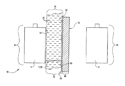
As shown in FIGs. 1-10, the present novel technology relates to a rechargeable
lithium metal electrochemical storage cell 10 having lithium metal electrodes
20. Referring
to FIG. 1, a rechargeable lithium electrode cell 10 is shown with a Li metal
cathode portion
12 and Li- metal anode portion 14. Separator 50 is positioned between the
anode 14 and
cathode 12. Separator 50 is typically coated with a layer 80 of functionalized
nanocarbons
particles 40. Separator 50 includes an anode facing side 53 and a cathode
facing side 52,
and is typically coated with a thin or very thin film 80 of the functionalized
nanocarbon
(FNC) particles 40, more typically about 0.1 gm thick, and typically oriented
facing the
surface 70 of the Li-metal electrode 20. Gap 26 is filled with an electrolyte
25 positioned
between the Li-metal electrode 20 and the FNC-coated separator 60. The
functionalized
nanocarbon particles 40 typically have Li+ ions immobilized on the surface 65
of the layer
80 of nanocarbon particles 40. The FNC film 80 is electrically connected to
the Li-metal
electrode 20. When the Li-metal electrode 20 is charged, Li dendrites 11
extend from the
4
CA 02836466 2013-11-05
WO 2012/158924 PCT/US2012/038360
surface 70 of the Li metal electrode 20 toward the FNC-coated separator 60.
Simultaneously, dendrites 55 extend from the surface 65 of the FNC film 80
toward the
surface 70 of the Li-metal electrode 20. The dendrites 55 grow in the through
plane
direction 94 of the Li metal electrode 20 and FNC coated separator 60.
Referring to FIG. 5, growth of dendrites 11, 55 is driven by the potential
difference
(AE) between the tip (Et) 59 and the base (Eb) 57 of the respective dendrites
11,55. With
cycling, dendrites 11, 55 continue extending toward each other; eventually,
the dendrites
11,55 touch each other and the potential difference (AE) dendrite 11, 55 is
approximately
zero because the FNC film BO and the Li-metal electrode 20 have the same
potential.
Consequently, dendrite 11, 55 growth is retarded or stopped along the through
plane
direction 94. In the subsequent cycles, dendrites 11, 55 may grow in a
direction
perpendicular to the major axis of the respective dendrite 11, 55 and parallel
to the plane
of the Li-metal electrode 20, also referred as the in-plane direction 84,
which prevents
dendrites 11, 55 from piercing through permeable or selectively permeable
membrane 50,
as shown in FIGs. 3A-3D. Eventually, a Li secondary surface 70 may form, from
the
intersection of the Li dendrites 11, 55. Thus, a composite Li metal electrode
20 is formed in
which an Li electrode 20 is assembled with the thin carbon layer 80.
While the lithium is typically specifically discussed herein as the electrode
metal, the
storage cell 10 may alternately include other alkaline earth and/or alkaline
metal elements
and combinations thereof as the electrode materials.
Two types of cell exemplary configurations for exploiting the Li-metal
dendrite/electrode system include a symmetric cell 400 in which a Li-metal
electrode 420
is used as both the anode 414 and the cathode 412, having the configuration of
CA 02836466 2013-11-05
WO 2012/158924 PCT/US2012/038360
Li/polymer/Li (anode/electrolyte/cathode=A/E/C), enabling Li-dendrite
mechanism study
or Li-polymer battery systems; and an asymmetric cell 500 in which Li metal is
the anode
514 and a different material is selected for the cathode 512, such as
Li/polymer
electrolyte/V205, Li/liquid electrolyte/graphite, Li/polymer
electrolyte/graphite, and
Li/polymer electrolyte/FePO4. The symmetric cell 400 provides a better medium
for Li-
metal dendrite growth and can accelerate the cycle testing, while the
asymmetric cell 500
better approximates field applications.
Dendrite growth, as shown in FIG. 5, is fundamentally unavoidable because the
metallurgic characteristics of Li-metal surfaces result in surface
imperfections of Li-metal
electrodes after the application of either mechanical stress or the
plating/stripping cycles.
While configurations known in the art focus solely on stopping dendrite 11
growth, the
novel cell design 10 focuses on controlling the direction of the Li-metal
dendrite 11,55
growth.
As described in FIG 9, one implementation 800 of the novel electrode 20 may
have a
carbon-coated layer of functionalized nanocarbon particles (FNC) 80 on a
separator 50 that
is positioned 801 in an electrolyte 25 and grows 803 Li dendrites 11, 55
simultaneously
from the surface 51 of the Li metal electrode 20 and the surface 65 of the FNC
coated
separator 60. An electrolyte 25 is placed 802 in the gap 26 the between the
electrode 20
and FNC- coated separator 60. The dendrites 11, 55 grow 803 after repeated
charging and
discharging 804 of the cell 10. Dendrites 11,55 contact each other 805 and
when contact
occurs, the dendrites 11, 55 stop extending in the through plane direction 94
due to the
zero potential difference that results from contact. The control of dendrite
growth
direction 800 occurs by contact 805 between the FNC coated separator dendrites
55 and
6
CA 02836466 2013-11-05
WO 2012/158924 PCT/US2012/038360
the electrode dendrites 11. After multiple combinations of dendrites 11, 55
the formation
806 of a Li- secondary Li surface 70 results.
The establishment of a zeroing potential difference gives the rechargeable Li-
metal
electrode 20 a high specific capacity, high cycle ability, and high safety.
Accordingly, the
rechargeable lithium metal electrode system 10 may be implemented in many
kinds of Li
batteries including Li-polymer, Li-air and Li-metal oxide cells and battery
systems as well
as any other cells or battery systems in which Li metal anodes 14 are used,
and yield
benefits for electronics, electric vehicles and hybrid electric vehicles,
large-scale energy
storage and the like.
Typically, a challenge for developing a high specific capacity and
rechargeable
Lithium metal electrode 20 for different Li batteries (i.e. Li polymer, Li-air
and Li-ion, etc),
has been stopping electrode dendrite 11 growth during the cycling 803. The Li-
metal
electrode 20 has an inherent metallurgic tendency to form dendrites 11, and
dendrite 11
growth is driven by the potential difference between the base 57 and the
dendrite tip 59.
Thus, Li electrode dendrite 11 growth is unavoidable. However, the instant
system 800
incorporates, rather than avoids, the dendrite growth mechanism.
In one embodiment, a rechargeable Li-metal electrode 220 is used in other Li
battery systems, such as Li-polymer and Li-air and may be fabricated by
coating the FNC
layers 280 on the polymer electrolyte membranes 200, which are used as the
electrolyte
225 in both Li-polymer batteries and Li-air batteries. These FNC-coated
polymer
electrolytes 225 are typically incorporated as the interlayer 280 and
assembled into a soft
packed Li-air cell 285. Such polymer electrolyte membranes 260 may include
those of
poly(ethylene oxide) (PEO), poly(vinylidene fluoride) (PVdF),
poly(acrylonitrile) (PAN),
7
CA 02836466 2013-11-05
WO 2012/158924 PCT/US2012/038360
and the other polymer electrolytes, which are widely used for both Li-polymer
batteries
and Li-air batteries.
Additionally, many modes of producing the FNC coated separator 60 are
available.
The FNC layer 80 plays a role in the novel Li-metal electrode 20 because the
immobilized
Li+ ions 30 in the FNC layer 80 serve as 'seeds' 31 for Li-metal dendrite 55
formation on
the FNC layer 80. The FNC layer 80 is typically porous, allowing the FNC
aggregates to be
bonded 605 together by the binder network 604 to form a rigid structure 606 to
hold 607
the integrity of the layer 80. The layer 80 is typically very thin with four
main properties:
1) good pore structure to facilitate the passage of Li+ ions therethrough, 2)
high electric
conductivity to reduce internal impedance, 3) high coverage of Li+ ions 30
over the
nanocarbon surface 65 for easy formation of Li metal dendrites 55, and 4) good
adhesion to
a polymer separator 50 or a polymer electrolyte membrane. All of these
properties are
similar to those for the catalyst layer in the fuel cell, (i.e. a porous layer
for gas and water
diffusion, electric conductivity necessitated for gas reactions, SO3- coverage
for proton
conduction, and good adhesion of the catalyst layer on the polymer electrolyte
membrane
for durability). The thinner the FNC layer 80, the less the loss of specific
capacity of the Li-
metal electrode 20.
The morphology of the FNC layer 80 depends on how the layer is fabricated 601.
Such techniques of applying 609 the layer 80 include (1) spraying, (2) machine
blade-
coating, (3) brush hand-painting, and the like. Carbons may be selected from
sources
including carbon blacks, nanographites, graphenes, and the like. It has been
found that the
higher the degree of graphitization, the higher the chemical stability. The
nanocarbon
particles 40 may be made from carbon black, which is inexpensive, but is an
amorphous
8
CA 02836466 2013-11-05
WO 2012/158924 PCT/US2012/038360
structure rather than a graphite structure. Graphene may also be used and
possesses
unique properties such as high electronic conductivity, high modulus, and high
surface
area.
The morphology of the FNC layer 80 is also influenced by the ink formulation.
To
make a thin carbon layer, the first step is to mix 600 the carbon source with
solvents to
make a uniformly dispersed suspension 603. To form such a well-dispersed
carbon ink,
solvent type is carefully selected based on polarity (i.e. dielectric
constant) and their
hydrophobicity in order to match those of the carbon aggregates and the
binders. This
mixture 602 is also called 'ink formulation'. The type of carbons and solvents
in an ink will
affect the morphology of the thin FNC layer 80. The type of binder 33 also
affects the
adhesion of the carbon layer 80 on the separator 50. Typically, the binder 33
has a similar
chemical structure to the separator/ electrolyte membrane 50 so that they can
be fused
together 605 through hot pressing or other techniques to form a well-bonded
interface 62
between the carbon layer 80 and the separator/electrolyte membrane 50.
The immobilized Li+ ions 30 over the surface of nanocarbon particles 40 serve
as
the 'seeds' 31 for Li dendrite 55 formation on the FNC-coated separator 60.
Immobilization
of the Li+ ions 30 is carried out by formation 900 of a dendrite seeding
material 61, such as
by diazonium reaction or similar means 902 on an appropriate 901 carbon
separator 50 to
chemically attach an SO3H group 902 onto the carbon surface 65, allowing the
carbon
separator 50 to become functionalized 903. Then, attached SO3H exchanges 906
with Li+
ions 30 to immobilize the Li+ ions 30 onto the surface 65. Thus, a dendrite
seeding
material 61 is formed 907. The dendrite seeding material 61 is typically
carbonaceous, but
may also be a metal substrate, such as Li, Na, K, Al, Ni, Ti, Cu, Ag, Au, and
combinations
9
CA 02836466 2013-11-05
WO 2012/158924 PCDUS2012/038360
thereof. The seeding material 61 may also be a functionalized metal substrate,
such as a
self-assembled monolayer structure comprised of Au with a thiol-terminated
organic
molecule that contains at least one function group, such as S03-M+, COO-M+,
and NR3+X-,
an electrically conductive organic polymer, such as polyacetylene,
polyphenylene vinylene,
polypyrrole, polythiophene, polyaniline, and plypohenylene sulfide, or a
functionalized
electrically conductive organic polymer, wherein the functional groups are
chemically
bound to the polymer. These materials 61 may be deposited using conventional
physical
deposition techniques, such as mechanical layering, or physical vapor
deposition
techniques, such a sputtering, or the like.
The novel technology allows attachment 903 of different functional groups to
the
carbon surface 65, such as through the diazonium reaction and the like. In
this reaction,
the functional group Y is attached 903 onto the carbon surface 65 through the
introduction
904 of a diazonium salt XN2C6H4-Y (wherein Y=Sulfonate, S03-M+, Carboxylate,
COO-M+;
and Tertiary amine, NR3+X-; etc.). The attachment of different chemical groups
not only
provides a platform for immobilizing Li+ ions 30 at the FNC surface 65, but
also changes
the surface energy of the carbon particles which can be used as a tool for
adjusting the
surface hydrophobicity of the carbon film 80, and is helpful for ink
formulation 603.
The adhesion 609 of the FNC layer to a separator/polymer electrolyte 50
influences
the cycle life of the novel Li-metal electrode 20. A good interface 62 between
the FNC layer
80 and the separator/electrolyte membrane 50 is typically formed 608. This
mainly
depends on the network of binders 33 in the FNC layer 80 and the techniques
for the
formation of the interface 62. Such a catalyst layer can withstand several
thousand hours of
long-term durability testing due, in part to the binder 33 in maintaining 607
the FNC layer
CA 02836466 2013-11-05
WO 2012/158924 PCT/US2012/038360
80 bound to the separator/electrolyte membrane 50. A TEM observation of such
this
catalyst/membrane interface 62 would show little or no delamination after
approximately
2000 hours of durability testing. Hot pressing is one of techniques for
fabrication, and the
parameters of the hot pressing technique (i.e. temperature, pressure, and
time) allow
systematic control of the process.
The morphology (i.e. surface area, pore structure, and geometry) of the FNC
layer 80
on the membrane 50 has a significant impact on the performance of the novel
metal
electrode 20. The FNC layer 80 porosimetry 81 (i.e. pore size, pore size
distribution and
pore volume) is a factor in controlling the direction of dendrite growth 700
because it
influences the presence 705 of metal cations 30 on the FNC membrane surface 65
and the
addition 703 of the dendrite seeding material 61 . The pore structure
typically allows metal
ions 30 to pass through smoothly during cycling 704, but not to form dendrites
inside the
pores that would block the diffusion of the metal ions 30. Thus, determining
701 and
production 702 of an appropriate FNC layer 80 with porosimetry 81 is useful in
allowing
for dendrite 11, 55 presence 706 and eventual formation 707 of a secondary
metal layer
70. On the other hand, the FNC layer 80 has to adhere to a separator/
electrolyte
membrane 50 and the diffusion barrier (if there is any) from the formed
interface 62
should be minimized.
Typically, the specific capacity of the rechargeable metal electrode 20 may be
affected by varying the thickness 89 of the FNC film 80 against the thickness
29 of the Li
metal electrode 20. The examples herein relate to the novel technology and
various
embodiments, and are not intended to limit the scope of the present novel
technology to
those modes and embodiments discussed herein.
11
CA 02836466 2013-11-05
WO 2012/158924 PCT/US2012/038360
Example 1:
The effect of the different carbon-coated layers on the specific capacity of
the Li
metal composite electrode 20 was approximately calculated and is shown in
Table 1. For
instance, for the carbon-coated layer 80 with the 0.1 gm thickness, the
corresponding
specific capacity loss of Li metal electrode 20 is only 0.026%. Even for the
thick FNC film
80, 4 gm, the corresponding loss of specific capacity is only 0.53%. Thus, the
effects of the
carbon-coated layer 80 on the specific capacity of the Li metal electrode 20
are negligible.
The thin carbon-coated layer 80 retains the advantage of the high specific
capacity of Li
metal electrodes.
Table 1
Thickness of Carbon Film Thickness of Li Metal
Reduction of Li Metal
(Itm) Electrode(mm) Electrode Specific Capacity
(0/0)
0.1 0.75 0.0133
1 0.75 0.1332
2 0.75 0.1332
3 0.75 0.1332
4 0.75 0.5305
Effect of thickness of carbon film on the Li metal electrode specific
capacity.
Therefore, carbon has been proven to be very stable in a wide potential
window. The
composite Li electrode having a very thin carbon film is very stable. Carbon
black may be
used in many battery systems (i.e. Zn/Mn02,), in particular, Li-ion batteries
(as the anode)
and Li-SOCl2 batteries (as the carbon cathode).
Referring to FIG 4, The Li metal anode 14 was assembled together with a
separator
350 (thickness=25 gm) coated with a thin nanocarbon layer 80 of functionalized
carbon
nanoparticles 340 (6=3.2 gm) and a LiPFe04 cathode 312 into a coin cell 300
configuration
12
CA 02836466 2013-11-05
WO 2012/158924 PCT/US2012/038360
using the electrolyte of 1.2 M LiPF6 in ethylene carbonate/ethyl-methyl
carbonate
(EC:EMC=3:7). A coin cell using the same components, but without the
nanocarbon coating
layer 380, was used as a baseline for the comparison. One concern for using
such a carbon
coating layer 380 is whether the addition of the FNC layer 380 on the
separator 350 would
result in the increased internal impedance from the carbon layer 380 blocking
the pores of
the separator 350, thus hindering the diffusion of Li+ ions 330 through and,
consequently,
reducing the power performance of the cell 300. However, it is clear that
coating the
carbon layer 380 on the separator 350 did not cause an increase in the
internal impedance
of the cell 300, but instead gave rise to a slight impedance reduction. The
Li/FNC cell 300
possesses a slightly higher discharge voltage than the baseline Li cell. Even
after five
hundred cycles, the same trend was observed. Noise was observed for the
baseline cell,
which was attributed to the formation of dendrites 355. In addition, the same
phenomenon
of reduction of internal impedance has been observed during the charging
process.
The cell 300 was not balanced for capacity, and the capacity of the cell 300
was
limited by the LiPFe04 cathode 312; a much higher capacity of the cell 300 is
expected if an
appropriate high energy density cathode is used (such as a V205 aerogel or an
air cathode).
The Li metal electrode 314 using an FNC layer 380 showed excellent
cycleablity,
approximately 84% capacity after 500 cycles. The estimated capacity decay rate
of the
novel Li metal electrode cell 300 after the first 45 cycles is only
0.026%/cycle. Based on
this decay rate, the cycle life of such a cell can typically achieve at least
500, more typically
at least 725 cycles, and still more typically at least 1000 cycles, with 80%
capacity (death
definition of a battery in electric vehicle (EV) applications). This decay
rate (0.026%/cycle)
of the novel Li metal electrode 320 in the coin cell 300 may be caused by the
degradation of
13
CA 02836466 2013-11-05
WO 2012/158924 PCT/US2012/038360
the LiFePO4 cathode 312 because the coin cells 300 are sealed in ambient
atmospheric
pressure, which may allow the introduction of moisture into the cell 300. The
moisture
reacts with LiPF6 to produce HF, which can react with LiFePO4, causing the
degradation.
Therefore, the true decay rate of the novel Li metal electrode 320 should be
much lower
than 0.026%/cycle if the coin cell 300 is sealed, such as inside an Argon
filled glovebox.
Example 2:
Referring to FIG. 6, an FNC-coated separator 60 was examined via SEM analysis
after
repeated cycling. Li metal dendrites 55 were observed on the surface 65 of the
FNC-coated
separator 60 facing the surface of the Li metal electrode 20. Moreover, the Li
dendrites 55
formed a unitary layer instead of aggregating as loosely arranged dendrites.
The thickness
89 of the FNC layer 80 was measured to be about 3 gm, while the Li dendrite 70
layer was
around 20 gm thick. Referring to FIG 6, and to further illustrate the function
of the FNC
layer BO for inducing Li metal dendrite 55 formation, the separator 50 was
coated with an
FNC layer 80 on half the area of the surface, while the other half was not
coated. No
dendrites 55 formed on the non-coated region of the separator 50. No Li
dendrites 55 were
found on the opposite side of the FNC-coated separator 50. Some large size
particles (50
gm or more) were observed seen underneath the separator 50; these large
particles likely
originated from the SEM conducting paste used to adhere the sample of the
separator 50 on
the SEM aluminum disc.
In another embodiment, the layer 80 formed over the electrochemical separator
50
to enable dendritic growth toward the metal anode 14 is a thin metallic layer
80. The
dendrites 55 growing from the separator 50 contact dendrites 11 growing from
the metal
14
CA 02836466 2013-11-05
WO 2012/158924 PCT/US2012/038360
anode 14, shorting the circuit and thus preventing the dendrites 11 growing
from the
anode 14 toward the separator 50 to reach and pierce the separator 50. The
anode 14 is
typically lithium, but may likewise be sodium or the like. The metal layer 80
on the
separator 50 is typically lithium, but may also be sodium or another
electrically conductive
metal, electrically conducting polymer, an organometallic matrix,
functionalized electrically
conducting polymer, or the like. More typically, the layer 30 is a non-
reactive metal, such
as Ni. The metal layer 80 on the separator 50 is typically formed thin enough
such that its
electrical resistivity is high, typically high enough such that the layer 80
is not easily
electrically or otherwise degraded. Optionally, the thin metal layer 80 may be
functionalized after deposition onto the separator 50.
While the novel technology has been illustrated and described in detail in the
drawings
and foregoing description, the same is to be considered as illustrative and
not restrictive in
character. It is understood that the embodiments have been shown and described
in the
foregoing specification in satisfaction of the best mode and enablement
requirements. It is
understood that one of ordinary skill in the art could readily make a nigh-
infinite number of
insubstantial changes and modifications to the above-described embodiments and
that it would
be impractical to attempt to describe all such embodiment variations in the
present
specification. Accordingly, it is understood that all changes and
modifications that come within
the spirit of the novel technology are desired to be protected.