Note: Descriptions are shown in the official language in which they were submitted.
CA 2836590 2017-04-26
WO 2012/170665 PCT/US2012/041306
WASHABLE LAYERED CUSHION
Technical .Field
This invention relates generally to cushioning systems for user comfort,
support,
and/or protection.
Background
Mattresses arc used in a wide variety of environments, such as in the home, in
hotels,
in hospitals. in sport facilities, in security facilities, in emergency
stations, during camping,
and for military applications. The mattresses provide comfort and impact
protection to a
user. Additionally, some mattresses may be port-able and provide a barrier
between the user's
body and one or more objects that would otherwise impinge on the user's body
in a variety of
settings. Similarly, various cushions provide similar benefits to a user as a
seating surface or
lining of a protective device (e.g., a helmet- or body pads).
A variety of structures and materials may be used to make a mattress or other
padding. For example, a pocketed spring mattress may contain an array of close-
coupled
metal springs that cushion the user's body from a bed frame. Additionally, an
array ofelose-
coupled closed-cell air andlor water chambers may be used, for exarnple, in
air and water
mattresses. Further examples include convoluted open or closed cell
polyurethane foam,
latex foam, and inversely convoluted foam.
However, conventional cushions, particularly mattresses in camping, military,
and
hospital applications, are difficult to clean between uses, and contaminants
often accelerate
the deterioration of such mattresses. The cushions often retain fluids a.nd
trap particles or
other foreign objects. Further, many portable or reusable cushions are
designed to maximize
transportability andlor storability rather than comfort. For example, a
conventional mattress
CA 02836590 2013-11-18
WO 2012/170665 PCT/US2012/041306
utilizing an array of coupled cells or springs provides an increasing
resistance to deflection
with deflection of the coupled cells or springs at a point of contact with the
user's body. The
increasing resistance to deflection may cause pressure points on the user's
body (e.g., at a
user's shoulders and hips) that protrude into the mattress more than other
portions of the
user's body. Additionally, conventional foam mattresses may result in
discomfort for a user
caused by excess compression or thermosetting. Further, conventional
mattresses may be
flammable or otherwise highly susceptible to fire hazards.
Summary
Implementations described and claimed herein address the foregoing problems by
providing a layered cushion comprising: a foam layer; a void cell layer; a
separation layer
configured to be oriented between the foam layer and the void cell layer; and
a cover
configured to envelop the foam layer and the void cell layer. The cover
constrains the foam
layer and the void cell layer in a selected position and orientation when
enveloping the foam
layer and the void cell layer. 'ale foam layer, the void cell layer, and the
cover arc removable
from one another.
Implementations described and claimed herein address the foregoing problems by
Further providing a method of assembling a layered cushion comprising:
positioning a foam
layer adjacent a first surface of a separation layer and within a cover;
positioning avoid cell
layer adjacent a second surface of the separation layer and within the cover;
and closing the
cover to envelop the foam layer and the void cell layer. The foam layer, the
void cell layer,
and the cover are removable from one anothcr.
Implementations described and claimed herein address the foregoing problems by
still
further providing a washable layered mattress comprising: a fluid permeable
foam layer; a
fluid permeable void cell layer including a matrix of four or more void cells;
a separation
layer oriented between the foam layer and the void cell layer; and a cover
that envelops and
constrains the foam layer and the void cell layer in a selected position and
orientation. The
foam layer, the void cell layer, and the cover are removable from one another.
Other implementations are also described and recited herein.
2
CA 02836590 2013-11-18
WO 2012/170665 PCT/US2012/041306
Brief Descriptions of the Drawiqg
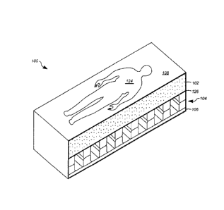
FIG. 1 illustrates a perspective cross-sectional view of an example washable
layered
mattress.
FIG. 2 illustrates an elevation cross-sectional view of an example helmet with
a
washable layered cushion therein.
FIG. 3 illustrates a partial cross-sectional view of an example layered
cushion.
FIG. 4 illustrates a perspective view of an example layered cushion in a fully
disassembled state.
FIG. 5 illustrates an elevation view of an example layered cushion with an
open
Cover.
FIG. 6 illustrates an elevation view of an example layered cushion in an
unloaded
state.
FIG. 7 illustrates an elevation view of an example layered cushion in a first
partially
loaded state.
FIG. 8 illustrates an elevation view of an example layered cushion in a second
partially loaded state.
FIG. 9 illustrates an elevation view of an example layered cushion in a
heavily loaded
state.
FIG. 10 illustrates an example pressure over deflection curve for component
and
system response characteristics of an example layered cushion.
FIG. 1 l illustrates example operations for assembling a layered cushion
according to
the presently disclosed technology.
FIG. 12 illustrates example operations for cleaning a layered cushion
according to the
presently disclosed technology.
Detailed Descriptions
FIG. 1 illustrates a perspective cross-sectional view of an example washable
layered
mattress 100. The layered mattress 100 includes a foam layer 102, a separation
layer 126, a
layer of void cells 104, a structure layer 106, and a cover 108. Details of
each of the
individual component layers of thc mattress 100 will be discussed in detail
below. FIG. I is
not drawn to scale.
3
CA 02836590 2013-11-18
WO 2012/170665 PCT/US2012/041306
The layered mattress 100 may sit atop a structural framework (not shown) that
lifts
the layered mattress 100 to a desirable height so that a user 124 may sit
andlor lie upon the
mattress 100 to comfortably rest and!or sleep. The component layers of the
mattress 100 are
specifically configured to be assembled and disassembled. This allows thc
individual
component layers of the mattress 100 to be replaced without replacing the
entire layered
mattress 100. Further, cach of thc individual component layers of thc mattress
100 arc fluid
permeable to enable easy cleaning of the layered mattress 100, either in an
assembled or
disassembled state, using water andlor a solution of water and a cleaning
agent.
FIG. 2 illustrates an elevation cross-sectional view of an example helmet 201
with a
washable layered cushion 200 therein. The layered cushion 200 includes a foam
layer 202, a
separation layer 226, a layer of void cells 204, and a cover 208. Details of
each of the
individual component layers of the layered cushion 200 will be discussed in
detail below.
FIG. 2 is not drawn to scale.
The layered cushion 200 may be inserted and secured within the helmet 201 to
comfortably cushion a user's head 224 from impacts. The component layers of
the
cushion 200 are specifically configured to be assembled and disassembled. This
allows
individual component layers of the cushion 200 to be replaced without
replacing the entire
layered cushion 200. Further, each of the individual component layers of the
cushion 200 are
fluid permeable to enable easy cleaning of the layered cushion 200, either in
an assembled or
disassembled state, using water and/or a solution of water and a cleaning
agent.
FIG. 3 illustrates a partial cross-sectional view of an example layered
cushion 300.
The layered cushion 300 includes a foam layer 302 and a layer of void cells
304 with a
separation layer 326 there between. The layered cushion 300 further includes a
structure
layer 306 and a cover 308 that at least partially encompasses the other
component layers of
the cushion 300. Further, the layered cushion 300 may include more or fewer
layers or
components as described herein. A portion of the cover 308 is missing to
illustrate the
component layers within the layered cushion 300.
The individual layers of the layered cushion 300 may be arranged in any order
or
manner. In an implementation, the cover 308 couples the other component layers
together
with the foam layer 302 providing, in conjunction with the cover 308, a user
interface. The
separation layer 326 may lie between the foam layer 302 and the layer of void
cells 304 to
prevent the foam layer 302 from collapsing into the individual cells of the
layer of void
cells 304. The structure layer 306 is the bottom-most layer of the layered
cushion 300. The
4
CA 02836590 2013-11-18
WO 2012/176665 PCT/11S2012/041306
layered cushion 300 reduces pressure points and maximizes comfort while
permitting the
transmission of fluids and particles through and out of each of the individual
layers for easy
cleaning. Low pressure support provided by the foam layer 302 and high
pressure support
provided by the layer of void cells 304 creates a layered cushion 300 that
contours to and
supports a user's body and that is soft and comfortable.
Thc foam layer 302 is porous and has low density that permits the easy
transmission
of fluids there through. The foam layer 302 is formed with relatively few
pores per inch, for
example, 25 to 35 pores per inch to maximize the hygienic characteristics
(e.g., the capability
to transmits fluids there through) of the foam layer 302. The foam layer 302
may be made of,
for example, urethane, an organic (e.g.. polyolefin) or an inorganic (e.g.,
silicone-based)
polymer, rubber, or any other material that is conformable, resilient, and has
a porous
structure that allows fluids and particles to move freely through the foam
layer 302.
In one implementation, the foam layer .302 is a reticulated urethane foam,
which has a
high tear strength, satisfactory elongation, and satisfactory resiliency.
Further, through
thermal reticulation, the pore sizes of the reticulated urethane foam may be
increased. In
another implementation, the foam layer 302 may be a cushion with
interconnected polymer
extrusions wandering in a spaghetti-like or net pattern. Because the foam
layer 302 is
designed to permit the easy transmission of fluids there through, the foam
layer 302 does not
readily retain fluid or trap particles. As such, the foam layer 302 may be
thoroughly cleaned
between uses.
Many porous, low density foams are susceptible to degradation and combustion.
Further, many such foams have low resistance to compression set. Conversely,
the foam
layer 302 is optimized to fight compression set, maximize durability, and
minimize
combustibility. The foam layer 302 may bc treated to make the foam material
fire retardant
or resistant to ignition from an open flame. For example, an intumescing
coating may be
applied to the foam layer 302 to make it fire retardant. Alternatively or
additionally, the
foam laver 302 may be made from an inherently fire retardant reticulated
urethane, which is
treated with additives at the compounding stage. Further, the low density
range of the foam
layer 302, for example, 2.2 to 3.0 pounds per cubic foot, increases the
resistance to
compression set, and the relatively low pores per inch of the foam layer 302
permits fluid
transmission through the foam layer 302. The resistance to compression set
increases the
durability of the foam layer 302 and allows for repeated use and cleaning of
the layered
cushion 300. Many types of foam soften in reaction to body heat, which may
result in
CA 02836590 2013-11-18
WO 2012/170665 PCT/US2012/041306
thermosetting of the foam. As such, in designing the foam layer 302, the
average
temperature of a human body andlor cxpcctcd storage, transportation, and usage
environment
temperatures are considered to prevent thermosetting of the foani layer 302.
The foam layer 302 contours to the user's body to maximize comfort and
interface
pressure reduction. The foam layer 302 contours and molds to the shape of the
user's body in
reaction to the user's body heat and weight and returns to its original form
oncc the pressure
from the user's body is removed from the foam layer 302. The firmness of the
foam layer
302 maximizes comfort and interface pressure reduction. For example, the foam
layer 302
may be 2 inches thick with a 55 percent usable stroke, which represents the
percentage of
compression before thc foam dcnsifies, and have a 25 to 35 indentation force
deflection
rating.
The layer of void cells 304 includes cushioning cells or support units
extending from
one or more substantially planar surfaces. The layer of void cells 304 may be,
for
example, 3.2 inches thick with a 70 percent usable stroke. As a result, the
layered
cushion 300 has a high degree of compliance while being relatively compact.
The cushioning
cells (or void cells) are hollow chambers that may create a relatively
constant force to resist
deflection. In one implementation, the cushioning cells are tapered. Further,
the cushioning
cells may be hexagonal, hemispherical, hemiellipsoidal, conical, cubical,
pyramidal,
cylindrical, etc. However, other shapes configured to resist deflection due to
compressive
forces are contemplated. The layer of void cells 304 is generally made from
materials that
are elastically deformable under expected load conditions and will withstand
numerous
deformations without fracturing or otherwise degrading. Example materials
include
thermoplastic urethane, thermoplastic elatomers, styrenic co-polymers, rubber,
Dow
Pellethane0. Lubrizol EstaneR), Dupontlm Hytrel*), ATOFINA PebaxV, and Krayton
polymers.
In one implementation, the layer of void cells 304 includes a top
substantially planar
surface opposing a bottom substantially planar surface, each surface having
one or more
indentations forming cushioning cells. For example, the cushioning cells may
have a 1.6
inches tall hemisphere with a 5-degree draft angle. The top surface links the
cushioning cells
extending from the top surface together, and the bottom surface links the
cushioning cells
extending from the bottom surface together. The cushioning cells extending
from a given
surface may be individually attached to that surface and not to each othcr. ln
the alternative,
the cushioning cells may extend from a given surface and further attach to
neighboring
6
CA 02836590 2013-11-18
WO 2012/170665 PCT/US2012/041306
cushioning cells. A cushioning cell extending from the top surface meets an
opposing
cushioning cell extending from the bottom surface at a connection interface.
The connection
interface may be perforated to allow for the transmission of fluids through
each of the
cushioning cells in the layer of void cells 304. Additionally, the surface
area of the top and
bottom surfaces corresponding to each cushioning cell may be open to further
permit the
transmission of fluids through thc layer of void cells 304. The open surfaces
and perforations
facilitate cleaning of the layer of void cells 304.
In another implementation, the individual cushioning cells arc arranged in a
top
matrix and a bottom matrix. The top matrix extends from a top surface of a
central binding
layer, and the bottom matrix extends from a bottom surface of the central
binding layer. In
onc implementation, the cushioning cells arc filled with ambient air and
closed or sealed to
prevent fluids or particles from penetrating or becoming trapped. In another
implementation,
the cushioning cells are un-filled. Further, there may be one or more holes in
the cushioning
cells and/or central binding layer through which air or fluid may pass freely
when the
cushioning cells arc compressed and de-compressed and/or to facilitate
cleaning. In yet
another implementation, the cushioning cells are filled with a foam or a fluid
other than air.
The foam or certain fluids may be used to insulate a user's body, facilitate
heat transfer from
the user's body to/from the layered cushion 300, and/or affect the resistance
to deflection of
the layered cushion 300.
In an iniplementation utilizing a central binding layer (not shown), the
cushioning
cells may compress independently of one another, within an independent
deformation range
to reduce the potential for pressure points on the user's body. The cushioning
cells
individually compress to distribute the weight of the user evenly. At least
the material, wall
thickness, size, and shape of each of thc cushioning cells define the
resistive force each of the
cushioning cells can apply. For example, the layer of void cells 304 may have
a 0.95 pounds
per square inch activation or buckling load and a 0.78 pounds per square inch
support force in
the active deflection range. This allows the layer of void cells 304 to
conform to the user's
body with an even force on the user's body to maximize comfort and reduce the
potential for
pressure points on the user's body. For example, the layer of void cells 304
has a sufficient
firmness to support a larger user (e.g., a user with a body weight greater
than the 75th
percentile) but also is capable of deforming and contouring to the body of a
smaller user (e.g.,
a user with a body weight less than thc 25th percentile). In another
implementation, the layer
of void cells 304 is a honeycomb structure.
7
CA 02836590 2013-11-18
WO 2012/170665 PCT/US2012/041306
Further, the layered cushion 300 achieves an optimal SAG factor, which
represents
the ratio of firmness between a foam layer and a secondary layer. For example,
the layered
cushion 300 may have a SAG factor of approximately 2 between the foam layer
302 and the
layer of void cells 304, which is optimal for pressure ulcer prevention.
In still another implementation, the cushioning cells are arranged in a top
matrix that
extends from a top binding layer and a bottom matrix that extends from a
bottom binding
layer. The void cells that extend from the top binding layer meet the bottom
binding layer
and the void cells that extend from the bottom binding layer meet the top
binding layer in an
interdigitated manner. The interdigitated layer of void cells may be
perforated where each
cushioning cell meets the opposite binding layer to facilitate cleaning and
allow the
transmission of fluids there through.
The structure layer 306 provides system firmness and rigidity to the layered
cushion 300 to maximize comfort and portability of the layered cushion 300.
The structure
layer 306 is planar and substantially rigid. The structure layer 306 evens the
surface the
layered cushion 300 is placed upon to maximize comfort to a user. Some
implementations
will not include the structure layer 306. The structure layer 306 may be made
from any rigid
material that does not retain fluids and that may be easily cleaned. For
example, the structure
layer 306 may be made of a plastic thermoplastic urethane. However, other
materials
including but not limited to metals, plastics, ceramics, and rubbers are
contemplated to make
the structure layer 306.
The cover 308 couples the layers, including the foam layer 302, the layer of
void cells 304, and the structure layer 306, together in a desired position
and orientation to
form the layered cushion 300 and prevents the component layers from
deteriorating as a
result of exposure to contaminants and/or environmental factors. The cover 308
may bc
removable to facilitate cleaning of the component layers separately and the
cover 308 may be
machine washable. Further, the cover 308 may be inherently fire retardant as a
result of the
material makeup, coating, etc. For example, thc cover 308 may be made from a
blend of
synthetic and natural fibers including but not limited to DupontTM Nomex0,
cotton, nylon,
and other aramid fibers. In an implementation, the cover 308 and the
separation layer 326
together includes a divider pocket to separate the foam layer 302 from the
layer of void cells
304 and to provide further structure to the layered cushion 300 and to prevent
the foam layer
302 from collapsing into the layer of void cells 304.
8
CA 02836590 2013-11-18
WO 2012/170665 PCT/US2012/041306
FIG. 4 illustrates a perspective view of an example layered cushion 400 in a
fully
disassembled state. The layered cushion 400 may be disassembled into
individual component
layers, a cover 408, a layer of void cells 404, a foam layer 402, and a
structure layer 406, to
facilitate storage or cleaning. Further, each individual component layer may
be treated with
anti-microbial substance and/or be made of an anti-microbial material.
In one implementation, each individual component layer may be replaced and
recycled without replacement of other component layers. For example, the layer
of void cells
404 and the structure layer 406 may be recycled into and/or reused as a new
layer of void
cells and a new structure layer, respectively. Further, the cover 408 and the
foam layer 402
may be recycled into a new cover and foam layer, respectively, and/or reused
for other
products. Because the layered cushion 400 may bc recycled and is easy to
clean, the layered
cushion 400 may be reused in a variety of environments, such as camping or
military
applications. Additionally, because the layered cushion 400 is hygienic and
may be easily
cleaned, the layered cushion 400 may be hygienically used by multiple users.
The cover 408 couples the component layers of the layered cushion 400 together
in a
desired position and orientation. The cover 408 is removable so that the
component layers
may be separated to facilitate cleaning (e.g., via opening a hook-and-loop
fastener 440
oriented along one side of the cover 408). The cover 408 may slip onto andlor
wrap around
the layers and it made include one or more other selectively detachable
fasteners (e.g., hook-
and-loop fasteners, buttons, snaps, etc.) to allow' for easy removal. The
cover 408 may also
be machine washable or cleaned by other methods.
Thc layer of void cells 404 includes two opposing surfaces with one or morc
open
cells extending from each surface. Each open cell meets an opposing open cell
at a
connection interface. The connection interface is perforated to facilitate
cleaning. Fluids,
such as water or cleaning agents, or air may be forced from the openings in
the surfaces
correlating to the open cells through the perforations in each connection
interface to flush out
contaminates. Fluids or air may be introduced at one surface of the layer of
void cells 404
and flushed through the perforations in each connection interface to the
opposite surface to
remove particles or contaminates.
The foam layer 402 permits fluids to move freely there through. Fluids andior
cleaning agents may be flushed from one end or side of the foam layer 402 to
the opposite
end or side to remove particles or contaminates from the foam layer 402.
Further, because
the foam layer 402 does not retain fluids, the time required for the foam
layer 402 to dry is
9
CA 0283 6590 2013-11-18
WO 2012/170665 PCT/US2012/041306
reduced as compared to other foams, which prevents molds or other moisture
born
contaminants from emerging in thc foam layer 402. The structure layer 406 is
rigid and does
not retain fluids. The structure layer 406 may be easily cleaned by rinsing
the structure layer
406 with fluids, such as water or cleaning agents.
FIG. 5 illustrates an elevation view of an example layered cushion 500 with an
open
cover 508. The layered cushion 500 includes the cover 508, a foam layer 502, a
layer of void
cells 504, and a structure layer 506. The cover 508 couples the individual
component layers
of the layered cushion 500 together in a desired position and orientation and
prevents the
individual component layers from deteriorating (e.g., by exposure to
environmental
elements). The layered cushion 500 further includes a separation layer 526 to
separate the
foam layer 502 from the layer of void cells 504 and to provide further
structure to the layered
cushion 500 and prevent the foam layer 502 from collapsing into the layer of
void cells 504.
In one implementation, the cover 508 and the separation layer 526 together
form a
pocket. The foam layer 502 is inserted into the pocket and provides a
comfortable interface
for a user. The foam layer 502 is optimized to fight compression, maximize
comfort, and
maximize durability, permitting multiple uses. The foam layer 502 contours to
the user's
body to maximize comfort and reduce pressure points on the user's body.
Further, the foam
layer 502 contours and molds to the shape of the user's body in reaction to
the user's body
heat and/or weight and returns to its original shape once pressure from the
user's body is
removed from the layered cushion 500.
The layer of void cells 504 is disposed between the foam layer 502 and the
structure
layer 506. The layer of void cells 504 includes a top substantially planar
surface 512 and an
opposing bottom substantially planar surface 510, each surface having one or
more tapered
cushioning cells (e.g., cushioning cells 514 and 516) protruding there from.
The cushioning
cells arc tapered hollow chambers that create a relatively constant force to
resist deflection.
While the cushioning cells depicted in FIG. 5 are generally truncated square
pyramids in
shape, the cushioning cells may be hemispherical, hemiellipsoidal, conical,
cubical,
pyramidal, cylindrical, or any other shape capable of having a hollow interior
volume.
The top surface 512 links the cushioning cells extending from the top surface
together, and the bottom surface 510 links the cushioning cells extending from
the bottom
surface together. Each cushioning cell extending from the top surface meets an
opposing
cushioning cell extending from the bottom surface at a connection interface.
For example,
cushioning cell 514 extends from thc top surface 512 to meet opposing
cushioning cell 516
CA 02836590 2013-11-18
WO 2012/170665 PCT/US2012/041306
extending from the bottom surface 510 at a connection interface 518. The
connection
interfaces are perforated (i.e., they have one or more holes passing there
through) to allow for
the transmission of fluids through each of the cushioning cells in the layer
of void cells 504.
Additionally, the surface arca of the top and bottom surfaces 512 and 510
respectively
corresponding to each cushioning cell is open to further permit the
transmission of fluids
through the layer of cushioning cells 504. The structure layer 520 is at the
bottom within thc
cover 508 and provides rigidity to the layered cushion 500. The structure
layer 520 is
substantially planar and rigid and evens the surface the layered cushion 500
is placed upon to
maximize comfort to the user.
FIG. 6 illustrates an elevation view of an example layered cushion 600 in an
unloaded
state. The layered cushion 600 includes a foam layer 602, a top matrix of void
cells 628, and
a bottom matrix of void cells 630. Both matrices of void cells 628, 630
collectively form a
layer of void cells 604 as discussed in detail herein. The foam layer 602 is a
porous and low-
density foam, for example, a reticulated foam. The foam layer 602 has a
resistance to
compression set and contours to a surface applying a load or pressure without
thermosetting.
The layered cushion 600 excludes a cover for illustration purposes (to allow
the foam layer
602 and the layer of void cells 604 to be viewed without obstruction).
The layered cushion 600 is placed in a compression test apparatus 620, which
includes a top surface 632 and a bottom surface 634. The layered cushion 600
is placed
between the top surface 632 and the bottom surface 634 of the compression test
apparatus 620. Compression is applied to the layered cushion 600 via the
compression test
apparatus 620. In the implementation of FIG. 6, no compressive force is
applied to the
layered cushion 600.
The top matrix of void cells 628 includes a top planar layer 612 of cushioning
cells
(e.g., cushioning cell 614) extending from the top planar layer 612. The
bottom matrix of
void cells 630 includes a bottom planar layer 610 of cushioning cells (e.g.,
cushioning cell
616) extending from the bottom planar layer 610. Each cushioning cell
extending from the
top planar layer 612 meets an opposing cushioning cell extending from the
bottom planar
layer 610 at a connection interface. For example, the cushioning cell 614
extends from the
top planar layer 612 to meet the opposing cushioning cell 616 extending from
the bottom
planar layer 610 at a connection interface 618.
In one implementation, the cushioning cells in the top matrix of void cells
628 and the
bottom matrix of void cells 630 each have a thickness that varies over a
height of the
11
CA 02836590 2013-11-18
WO 2012/170665 PCT/US2012/041306
cushioning cell. For example, where the cushioning cell 614 nears the top
planar layer 612,
thc wall thickness of thc cushioning cell 614 may be greater than where the
cushioning cell
614 nears the connection interface 618, or visa versa. Varying the thickness
of the
cushioning cells over their height may be used to yield a changing resistive
force depending
upon the amount of compression of the cushioning cells (i.e., yielding a
positive and/or
increasing spring rate). Additionally, thc top matrix of void cells 628 may be
a different
thickness than the bottom matrix of void cells 630.
FIG. 7 illustrates an elevation view of an example layered cushion 700 in a
first
partially loaded state. The layered cushion 700 includes a foam layer 702, a
top matrix of
void cells 728, and a bottom matrix of void cells 730. Both matrices of void
cells 728, 730
collectively form a layer of void cells 704 as discussed in detail herein. The
foam layer 702
is a porous and low-density foam, for example, a reticulated foam. The foam
layer 702 has a
resistance to compression and contours to a surface applying a load without
thermosetting.
The layered cushion 700 excludes a cover for illustration purposes (to allow
the foam layer
702 and the layer of void cells 704 to be viewed without obstruction).
The top matrix of void cells 728 and the bottom matrix of void cells 730
include
cushioning cells (e.g,., cushioning cells 714 and 716). Each cushioning cell
meets an
opposing cushioning cell at a connection interface. For example, the
cushioning cell 714
meets the cushioning cell 716 at a connection interface 718. The cushioning
cells deform and
compress as a load is applied to one or more of the void cells.
The layered cushion 700 is placed in a compression test apparatus 720, which
includes a top surface 732 and a bottom surface 734. The layered cushion 700
is placed
between the top surface 732 and the bottom surface 734 of the compression test
apparatus 720. A load
(e.g., 19.0 lb.) is applied to the layered cushion 700 via the compression
test apparatus 720.
The foam layer 702 compresses before the top matrix of void cells 728 and the
bottom matrix
of void cells 730 begin to compress. The foam layer 702 contours to the shape
of the top
matrix of void cells 728 and begins to collapse into the cushioning cells in
the top matrix of
void cells 728. Because the load in the testing apparatus 720 is applied to
the foam layer 702
evenly, the foam layer 702 evenly compresses. The load is insufficient to
compress the
cushioning cells in the top matrix of void cells 728 or bottom matrix of void
cells 730. For
example, cushioning cells 714 and 716 are not compressed. In another
implementation, when
the layered cushion 700 includes a separation layer between the foam layer 702
and the layer
12
CA 02836590 2013-11-18
WO 2012/170665 PCT/US2012/041306
of void cells 704, the foam layer 702 is prevented from contouring to or
collapsing into the
cushioning cells in the top matrix of void cells 728.
FIG. 8 illustrates an elevation view of an example layered cushion 800 in a
second
partially loaded state. The layered cushion 800 includes a foam layer 802, a
top matrix of
void cells 828, and a bottom matrix of void cells 830. Both matrices of void
cells 828, 830
collectively form a layer of void cells 804 as discussed in detail herein. The
foam layer 802
is a porous and low-density foam, for example, a reticulated foam. The foam
layer 802 has an
resistance to compression and contours to a surface applying a load without
thermosetting.
The layered cushion 800 excludes a cover for illustration purposes (to allow
the foam layer
802 and the layer of void cells 804 to be viewed without obstruction).
The top matrix of void cells 828 and the bottom matrix of void cells 830
include
cushioning cells (e.g., cushioning cells 814 and 816). Each cushioning cell
meets an
opposing cushioning cell at a connection interface. For example, the
cushioning cell 814
meets opposing the cushioning cell 816 at a connection interface 818. The
cushioning cells
deform and compress as a load is applied to one or more of the void cells.
The layered cushion 800 is placed in a compression test apparatus 820, which
includes a top surface 832 and a bottom surface 834. The layered cushion 800
is placed
between the top surface 832 and the bottom surface 834 of the compression test
apparatus 820. A load
(e.g., 23.3 lb.) is applied to the layered cushion 800 via the compression
test apparatus 820.
The testing apparatus 820 is applying a greater force than the test apparatus
720 of
FIG. 7, and is compressing the layered cushion 800 further. The foam layer 802
compresses
before the top matrix of void cells 828 and the bottom matrix of void cells
830 begin to
collapse. The foam layer 802 contours to the shape of the top matrix of void
cells 828 and
collapses into and around thc cushioning cells in thc top matrix of void cells
828. Because
the load in the testing apparatus 820 is applied to the foam layer 802 evenly,
the foam layer
802 evenly compresses.
The top matrix of void cells 828 and bottom matrix of void cells 830 each
collapse to
create a relatively constant force to resist deflection. For example, the
cushioning cells 808
and 812 in combination with the foam layer 802 individually compress and
conform to a
user's body with an even force on the user's body to maximize comfort and
reduce the
potential for pressure points on the user's body. In another implementation,
when the
layered cushion 800 includes a separation layer between the foam layer 802 and
the layer of
13
CA 02836590 2013-11-18
WO 2012/170665 PCT/US2012/041306
void cells 804, the foam layer 802 is prevented from contouring to or
collapsing into the
cushioning cells in the top matrix of void cells 828.
In various implementations, the top matrix of void cells 828 has a lower
resistance to
deflection and thus collapses before the bottom matrix of void cells 830,
which has a higher
resistance to deflection. However, in other implementations, the bottom matrix
of void
cells 830 has a lower resistance to deflection and thus collapses before the
top matrix of void
cells 828. In yet other implementations, the top matrix of void cells 828 and
the bottom
matrix of void cells 830 have the same or similar resistance to deflection and
thus collapse
simultaneously or nearly simultaneously.
FIG. 9 illustrates an elevation view of example layered cushion 900 in a third
heavily
loaded state. The layered cushion 900 includes a foam layer 902 and a layer of
void
cells 904. The layer of void cells 904 is arranged in a top matrix and a
bottom matrix, which
are indistinguishable in the heavily loaded state depicted in FIG. 9. The
layer of void
cells 904 includes multiple cushioning cells that deform and compress as a
load is applied to
the layer of void cells 904.
The foam layer 902 is a porous and low-density foam, for example, a
reticulated
foam. The foam layer 902 has a resistance to compression and contours to a
surface applying
a load without thermosetting. The layered cushion 900 excludes a cover for
illustration
purposes (to allow the foam layer 902 and the layer of void cells 904 to be
viewed without
obstruction).
The layered cushion 900 is placed in a compression test apparatus 920, which
includes a top surface 932 and a bottom surface 934. The layered cushion 900
is placed
between the top surface 932 and the bottom surface 934 of the compression test
apparatus 920. A load
(e.g., 35.8 lb.) is applied to the layered cushion 900 via the compression
test apparatus 920.
The testing apparatus is applying a greater force than the test apparatus 914
of FIG. 8,
and is compressing the layered sleep system components 900 further. The foam
layer 902
compresses before the layer of void cells 904 collapses. The foam layer 902
contours to the
shape of the layer of void cells 904 and collapses into and around the
cushioning cells in the
layer of void cells 904. Because the load in the testing apparatus 920 is
applied to the foam
layer 902 evenly, the foam layer 902 evenly compresses. Further, the layer of
void cells 904
is almost fully collapsed and the individual void cells are no longer
distinguishable from one
another.
14
CA 02836590 2013-11-18
WO 2012/170665 PCTPUS2012/041306
FIG. 10 illustrates an example pressure over deflection curve 1000 for
component and
system response characteristics of an example layered cushion. The graph 1000
illustrates
thc relationship between pressure (in pounds per square inch) and deflection
(in inches) of a 2
inch foam layer (1051), a4 inch layer of void cells (1052), and a layered
cushion system
including both the 2 inch foam layer and the 4 inch layer of void cells
(1053).
The graph 1000 illustrates a difference in activation and support pressure
between the
three curves. The 2-inch foam layer has an initial yield point 1036 that
provides lower
pressure support to a user's body. The lower pressure support of the 2-inch
foam layer
maximizes comfort and interface pressure reduction. "the layer of void cells
has a higher
initial yield point 1038, which provides displacement under higher loads,
which in turn
provides support for larger and/or more protruding features of the user's body
(e.g., the user's
shoulders or hips).
The layered cushion system including both the 2-inch foam layer component and
the
layer of void cells component combines the low and high-pressure support
advantages of
the 2-inch foam layer and the layer of void cells. As a result, curve 1053
does not have a
distinct initial yield point and overall has a smoother pressure-deflection
profile than curves
1051 and 1052. Accordingly, the layered cushion system combines the low and
high
pressure support of the 2-inch foam layer component and the layer of void
cells component to
provide a layered cushion that contours to and supports the user's body and
that is soft and
comfortable to the user.
FIG. 11 illustrates example operations 1100 for assembling a layered cushion
according to the presently disclosed technology. A first positioning operation
1110 positions
a foam layer within a pocket of a layered cushion cover. In one
implementation, the foam
layer is made of a fluid permeable foam with a pore size large enough to
facilitate
transmission of fluids through the foam layer with relative ease. The foam
layer collapses
under a load and provides a user a comfortable interface with the layered
cushion. In one
implementation, the layered cushion cover is made of a permeable flexible
material (e.g.,
fabric or mesh). Further, the pocket may be formed contiguously with the
layered cushion
cover and made of the same material as the layered cushion cover.
A second positioning operation 1120 positions a void cell layer adjacent the
foam
layer within the layered cushion cover with a separation layer there between.
The void cell
layer includes multiple cushioning cells or support units extending from one
or more
substantially planar surfaces. Thc individual cushioning cells collapse under
a load, and the
CA 02836590 2013-11-18
WO 2012/170665 PCT/US2012/04.1306
void cell layer collapses under a relatively greater load than the foam layer.
This provides the
user additional support. The separation layer may be formed contiguously with
the layered
cushion cover and made of the same material as the layered cushion cover or it
may be a
separate structure attached to the layered cushion cover. Further, the
separation layer may be
the interior portion of the aforementioned pocket.
A third positioning operation 1130 positions a rigid layer adjacent the void
cell layer,
away from the foam layer. and within the layered cushion cover. The rigid
layer provides a
structural foundation for the layered cushion and may be made of any rigid
material (e.g.,
wood, plastic, metal). In some implementations, a separate pocket within the
layered cushion
cover receives the rigid layer. In other implementations, no rigid layer is
included in the
layered cushion because the layered cushion is intended to be placed on a
rigid surface.
A closing operation 1140 closes the layered cushion cover around the foam
layer, the
void cell layer, and the rigid layer. This envelops and secures the layers in
a desired position
and orientation within the layered cushion cover. In one implementation, the
layered cushion
cover is equipped with selective fasteners (e.g., hook-and-loop, buttons,
snaps. etc.) oriented
along at least 1 side of the layered cushion cover. The layers are inserted
through the open
side(s) of the layered cushion cover and the layered cushion cover is
selectively closed
around the layers.
FIG. 12 illustrates example operations 1200 for cleaning a layered cushion
according
to the presently disclosed technology. An opening operation 1210 opens the
layered cushion
cover to reveal an enveloped foam layer, void cell layer, and rigid layer
within the layered
cushion cover. ln one implementation, the opening operation 1210 is
accomplished by
selectively detaching selective fasteners (e.g., hook-and-loop, buttons,
snaps, etc.) oriented
along at least 1 sidc of the layered cushion cover.
A removing operation 1220 removes the foam layer, the void cell layer, and the
rigid
layer from the layered cushion cover. In one example implementation, the
removing
operation 1220 may be performed by merely physically pulling each of the foam
layer, the
void cell layer, and the rigid layer from the layered cushion cover. A
flushing operation 1230
flushes one or more of the foam layer. the void cell layer, the rigid layer,
and the cover with a
cleansing fluid. The cleansing fluid may include water and one or more
cleansing and/or
anti-microbial agents (e.g., soaps and chemicals) to facilitate cleansing of
the layered
cushion. More specifically, thc cleansing fluid may pass over and through
holes and/or pores
16
CA 02836590 2013-11-18
WO 2012/170665 PCT/US2012/041306
in the foam layer, the void cell layer, the rigid layer, and/or the cover to
flush contaminants
from thc foam layer, the void cell layer, the rigid layer, and/or the cover.
A drying operation 1240 dries the foam layer, the void cell layer, the rigid
layer,
and/or the cover. The drying operation 1240 rnay be performed on one or more
of the layers
that was flushed in the flushing operation 1230. The drying operation 1240
further may be
performed merely by ambient temperature evaporation or by the application of
heat and/or
forced air to the foam layer, the void cell layer, the rigid layer, and/or the
cover to facilitate
the evaporation. A reassembling operation 1250 reassembles the foam layer, the
void cell
layer, the rigid layer, and/or the cover. In one implementation, thc
reassembling operation
1250 may be performed using the operations 1100 of FIG. 11.
The logical operations making up the embodiments of the invention described
herein
are referred to variously as operations, steps, objects, or modules.
Furthermore, it should be
understood that logical operations may be performed in any order, adding
and/or omitting
steps as desired, unless explicitly claimed otherwise or a specific order is
inherently
necessitated by the claim language.
The above specification, examples, and data provide a complete description of
the
structure and use of exemplary embodiments of the invention. Since many
embodiments of
the invention can be made without departing from the spirit and scope of the
invention, the
invention resides in the claims hereinafter appended. Furthermore, structural
features of the
different embodiments may be combined in yet other embodiments without
departing from
the recited claims.
17