Note: Descriptions are shown in the official language in which they were submitted.
CA 02836673 2013-11-19
AN AUTONOMOUS VALVE ASSEMBLY FOR THE REGULATION,
DEPRESSURIZATION AND PRESSURIZATION OF PNEUMATIC
EQUIPMENT
STATE OF THE ART OF THE INVENTION
Field of the Invention
The current invention is related to the field of
devices that are used in equipment that works with
pneumatic pressure and where there's a need for regulation,
such as the pressurization and depressurization of the
pneumatic circuits, more particularly the invention refers
to an autonomous valve assembly for the pressurization,
depressurization and regulation of the pressure in a
pneumatic circuit such as an inflation/disinflation circuit
for the tires of a motor vehicle.
Although the present invention's main application
will be in a circuit to maintain the pressure in the tires
of a vehicle, it is evident that the invention can be
applied to any circuit that controls the pressure of fluid
in order to trigger different types of working equipment.
Description of the prior art
The different systems to maintain, increase,
decrease and in general regulate the pressure in fluid
1
CA 02836673 2013-11-19
circuits, such as pneumatic circuits are very well known in
the field of the invention. These systems generally consist
of valve assemblies and combinations that receive a
pressurized fluid, for example air, and channel it through
several valves and plungers that multiply the pressure
received by the elevation system. These include, among
others, valve bodies with pressure regulators that are
connected to a source of pressure, for example a
pressurized air tank, and the pressurized air passes
through the different valves, causing the cyclical movement
of some of the pistons, spool valves, etc. that guide the
fluids to other pistons and plungers that pressurize the
fluid in order to obtain a greater pressure in the fluid at
the outlet of the elevation system than there was at the
inlet.
Among said valve assemblies is the elevation system
described in the Patent EP 1265761 B1 and US 6269691, which
refer to an automatic inflation system for the tires of
motor vehicles. This elevation system consists of a
combination of spool valves and retention valves with
reciprocating movement whose coordinated movements are
complex to be maintained efficiently. In general, the
components such as the pistons or spool valves lock up or
do not repeat their cycle continuously if their design is
not appropriate.
2
CA 02836673 2013-11-19
The Patent Application No. 1265761, presented on 17
March 2000, and granted on 7 August 2001 reveals a pressure
elevation system for compressed air installations that are
used to maintain pressure in the tires of a motor vehicle.
This elevation system contains a device with an air inlet
that is connected to a source of compressed air of the
vehicle, an air regulator which presents said compressed
air inlet, a valve body which is connected to said
regulator and that receives compressed air from the source
and that includes an air-diverting plunger that moves
reciprocatingly in order to cyclically divert the
compressed air through the ducts to an air compression
.
chamber which contains compressing plunger assembly which
has been arranged to move reciprocatingly within the
compression chamber and defines external and internal
compression chambers, to compress the air provided in said
air intake and increase the pressure to a level that is
higher than at said intake. This compressing plunger
assembly consists of a rod that contains plungers on both
ends that move sealedly within said air compression
chamber, and said rod is mounted within said valve body
which furthermore has inlet valves to channel the
compressed air and outlet valves to release the air that
has been used to compress the air whose pressure needs to
be increased. The valve body also presents valve plungers
3
CA 02836673 2013-11-19
. 4
to cyclically route the air towards said diverter plunger
in order to make said diverter plunger move cyclically with
reciprocating movement.
The above-mentioned elevation system shows several
functional faults. For example, this well-known elevation
system presents an air compression plunger with a rod that
causes the decompression of the escape chamber through an
orifice that is connected to the inlet pressure, i.e. with
an air inlet orifice between the regulator and the valve
body.
Furthermore, the decompression of the elevation
system's compression chambers is achieved by means of an
orifice that is located in the casings of the diverter
plunger to lead the air out into the atmosphere. This
causes faults in the cyclical operation of the diverter
plunger which eventually lock up. Consequently, this known
elevation system incorporates a lever on the casing and
pressurization chamber that is used to move the diverter
plunger.
However, the valve plungers of the known system are
moved by the force of the pressurization plungers but
return to their previous position. Therefore, if this
movement happens very quickly, not enough air enters to
move the diverter plunger, as a result of which the plunger
4
CA 02836673 2013-11-19
, r
stays in the same position and when this happens it is
necessary to use the previously mentioned lever.
Nonetheless, it is worth mentioning that in the
elevation systems of the same kind that are known in the
art, the inlet and outlet valves are located on the casings
of the pressurization chambers, and the rod of the
pressurization plunger assembly presents decompression
orifices, which generates the same above-mentioned problem,
i.e. the diverter plunger locks up and the equipment stops
functioning.
In the above-mentioned and other assemblies for the
regulation and increase of pressure for the inflation of
automotive transport tires, electrical or electronical
circuits, electronical contacts, connection cables, etc. to
guarantee the power supply of the equipment and to provide
the operator or driver of the vehicle with the necessary
visual or auditive indications about the correct operation
of the regulation elevation equipment.
These circuits,
obviously, make the installation of this equipment more
expensive.
Another restriction for the pressure regulation and
control equipment for automotive tires and other systems
that use fluid pressure is that the equipment is adjusted
for a single pressure regulation value.
CA 02836673 2013-11-19
, .
Considering the regulation and pressure elevation
systems that are described in the prior art and taking into
account their deficiencies, it would be very convenient to
have a new elevator-regulator that does not need extra
energy for its operation, for example from power supply
circuits, that also allows sufficient time to be able to
move the valve plungers preventing that they return to the
position they were in previously and locking them in their
position, and that provides more than one established
regulation pressure and is also safe and free of faults.
BRIEF DESCRIPTION OF THE INVENTION
Therefore, it is a goal of the present invention to
provide a valve assembly for the regulation and pressure
elevation in pneumatic equipment, as for example in systems
or equipment to keep the tires of a vehicle inflated, being
an autonomous assembly that does not need extra power
supply, for example electrical energy, and it is capable of
raising the pressure of the pneumatic system or equipment
with at least 75%.
It is another objective of the current invention to
provide an autonomous valve assembly for the regulation and
elevation of the pressure in pneumatic equipment that
present a valve body and an air regulator body with an
6
CA 02836673 2013-11-19
compressed air intake connected to a source of compressed
air, whereby the body presents two pressure regulators that
regulate the pressure at a desired level and communicate it
to an air diverter plunger with reciprocating movement to
cyclically divert the compressed air to a pressurization
plunger assembly that has a reciprocating movement within a
pressure casing wherein said air pressure regulators are
adjusted to regulate the passage of air to a first pressure
and a second pressure.
It is yet another objective of the current
invention to provide an autonomous valve assembly for the
pressure regulation and elevation in pneumatic equipment,
being an assembly of the type that contains an air
regulation body with a compressed air inlet connected to a
source of compressed air, a valve body that is connected to
said regulation body to receive compressed air from it and
that includes an air diverter plunger with reciprocating
movement to cyclically divert the compressed air through
the ducts to a pressurization plunger with a reciprocating
movement within a pressure casing, defining internal and
external pressurization chambers inside of which the
compressed air from said air intake is compressed and the
pressure is elevated above the pressure at the point of
entry. Said pressurization plunger assembly includes a rod
that is mounted slidingly within a duct of said valve body
7
CA 02836673 2013-11-19
that runs through the valve body connecting said internal
pressurization chambers, said rod having, at both ends, two
pressurization plungers that slides sealingly within said
air pressurization case, said rod being mounted slidingly
over said valve body, and said valve body presenting inlet
valves to channel the highly compressed air for its later
usage and outlet valves to let the compressed air escape,
and valve plungers to cyclically direct the air towards
said diverter plunger to make said diverter plunger move
cyclically with reciprocating movement, where said air
regulation body contains a first compressed air regulator
that is adjusted to a first pressure and a second
compressed air regulator that is adjusted to a second
pressure, whereby a selection switch is mounted between
said regulators to activate one of them.
It is even another objective of the present
invention to provide an autonomous valve assembly for the
regulation and elevation of the pressure in pneumatic
equipment, that presents a valve body and an air regulation
body with a compressed air inlet connected to a source of
compressed air, wherein the body presents two pressure
regulators that regulate the pressure to a desired value
and communicate it to an air diverter plunger with
reciprocating movement to cyclically divert the compressed
air towards a pressurization plunger assembly, said
8
CA 02836673 2013-11-19
compressed air inlet being connected to a feed orifice that
is connected to diversion orifices that are selectively
connected to external and internal chambers of said
diversion plunger, and said internal chamber of said
diversion plunger are alternately connected to an orifice
that feeds a power-generating turbine.
BRIEF DESCRIPTION OF THE DRAWINGS
For greater clarity and understanding of the
objective of the current invention, it has been illustrated
in several figures, where the invention has been
represented in one of the preferred embodiments, all by way
of illustration, wherein:
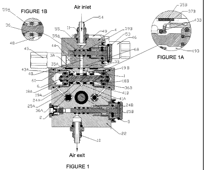
Figure 1 shows a side-section view of the pressure
elevation system in agreement with a preferred embodiment
of the invention;
Figure 1A shows an enlarged detail limited by the
circle in Figure 1;
Figure 1B shows an enlarged detail limited by the
circle in Figure 1;
Figure 2 shows a side-section view similar to that
of Figure 1 but with the switch in another position;
Figure 2A shows an enlarged detail limited by the
circle in Figure 2;
9
CA 02836673 2013-11-19
. .
Figure 3 shows a side-section view of the pressure
elevation assembly in Figure 1, at the level of the
pressure regulators and the selection switch and rotated by
900 with respect to the section in Figure 1;
Figure 4 shows a perspective cut-away view of one
of the pressure regulators;
Figure 5 shows a side-section view of the pressure
elevation assembly in Figure 3, at the level of the
pressure regulators and the selection switch and rotated by
900 with respect to the section in Figure 3;
Figure 6 shows a side-section view of the
pressurization plunger assembly according to the invention;
Figure 7 shows a side-section view of the
pressurization plunger assembly of Figure 6 but in another
working position;
Figure 7A shows an enlarged detail limited by the
circle in Figure 7;
Figure 7B shows an enlarged detail limited by the
circle in Figure 7;
Figure 8 shows a side-section view of the valve
body at the level and in the longitudinal field of the
pressurization plunger assembly but without said plunger's
components;
CA 02836673 2013-11-19
Figure 9 shows a side-section of the pressurization
plunger assembly of Figure 6 and 7 but in another working
position;
Figure 9A shows an enlarged detail limited by the
circle in Figure 9;
Figure 9B shows an enlarged detail limited by the
circle in Figure 9;
Figure 10 shows a side-section view similar to that
of Figure 1 but with the switch in another position;
Figure 10A shows an enlarged detail limited by the
circle in Figure 10;
Figure 11 shows a side-section view similar to that
of Figure 10 but with the depressurization knob in another
position;
Figure 11A shows an enlarged detail limited by the
circle in Figure 11;
Figure 12 shows a view from one end of a plunger of
the inlet and outlet valves of the pressurization plunger
assembly, where the blades for support of the plunger and
passage of the fluid can be seen.
DETAILED DESCRIPTION OF THE INVENTION
Referring now to the figures we see that the
invention consists of an autonomous valve assembly for the
H
,
CA 02836673 2013-11-19
pressure regulation and elevation in pneumatic equipment of
an automotive vehicle, being an assembly of the type that
comprises an air pressure regulation body 4 with a
compressed air inlet 54 that is connected to a source of
compressed air that has not been illustrated and can be any
of the types known in the art. For example, this could be a
tank of compressed air as is known in the art.
Figure 1 shows that the compressed air from said
tank enters through the orifice or inlet 54 through an
input socket 11 threaded onto the valve body or the
regulation body 4. This body 4 presents an orifice 55 that
is extended transversally to the orifice 54, as can be seen
more clearly in Figure 5, and that connects the two inlet
orifices 57A and 57B, which correspond to pressure
regulators 45 and 46 respectively.
In Figure 4 it can be observed that the air that
enters orifice 57A passes through the regulator 45 until it
reaches orifice 58A. It is worth mentioning that these two
regulators 45 and 46 are constantly under air pressure, as
they are interconnected through orifice 55 which can be
located on body 4 of the regulators. Once the compressed
air passes through orifice 58A, it has the pressure to
which the regulator has been set, entering once again the
body 4 through orifice 59A, as can be observed in Figure 3.
12
CA 02836673 2013-11-19
Body 4 also includes a selection switch 53 in order
to switch the compressed air from inlet 54 to one of the
regulators 45, 46. In accordance with Figure 1, the
position of the selection switch 53, the compressed air
that comes from the outlet orifice 59A or 59B is only
connected to the feed orifice 48, because in this position
the axle or rod of the switch or knob 53 has a switching
groove 36, which allows for both orifices 59A and 48 to
connect, see Figure 1B. In other words, in this position of
Figure 1 only the air pressure which has been regulated
through regulator 45, shall pass through.
If we want to feed the assembly with a different
air pressure, the selection switch 53 is moved to the
position shown in Figure 2, then the pressure that is
present in orifice 48 will be the pressure that is found in
the regulator 46. This happens because when the knob is
moved in order to change the state, the groove 36 from the
knob axle will be in another position where it is retained
using a ball 50. It is worth mentioning that the separation
that keeps the orifices 59A and 59B with the orifice 48, is
adequately sealed using o'rings or toroidal seals 70A and
69A, as can be seen better in Figure 2A.
Once the pressurized air is moving through orifice
48, it moves towards a duct or orifice 1 on the valve body
22. Orifice 1 is connected continuously with orifice 2, and
CA 02836673 2013-11-19
, .
alternately with diversion orifices 3A or 3B, according to
the position of the diversion plunger 6. For example, in
Figure 1 we can see that orifice 1 is connected to orifice
3A.
The valve body 22 contains the seals 41A and 41B
that seals the connection between the orifices 3A or 3B so
these orifices are never connected to each other. Orifices
3A and 3B connect the Chambers 8A and 8B, and the orifice 2
connects chambers 7A and 7B continuously.
The valve body 22 also contains seals 43A and 43B,
which prevent the air that comes from orifice 1 from
reaching the chambers 19A and 19B that can be observed in
Figure 1.
In Figure 6 it can be observed that the air from
orifice 3A is led through the internal part of casing 20A,
through the schematically illustrated orifice 38A,
continuing to a cover 17A that is fixed to the casing 20A,
hereby allowing the air to reach chamber 8A. Once the air
enters chamber 8A, pressure is applied on the surface of a
plunger or piston 9A, allowing for the plunger and all of
its assembly to move to the right, as can be observed in
Figure 6. The plunger 9A forms part of the pressurization
plunger assembly composed by a rod 5 and a pair of plungers
9A and 9B.
14
CA 02836673 2013-11-19
Orifice 2 distributes the air over the spring-
charged (15A and 15B) inlet plungers 14A or 14B that are
extended within the valve body 22, between the internal
pressurization chambers 7A and 7B. In the case of Figure 6,
the air moves plunger 14B considering that the pressure
within chamber 7A applies pressure on plunger 14A. The air
pressure in chamber 7A is greater than the pressure that
comes in through orifice 2, moving plunger 14B and
consequently overpowering spring 15B. Under these
conditions, the air will enter chamber 7B and will be
compressed. This compression happens because the volume of
the air that is present inside of the chamber 7A decreases
which causes the pressure within this enclosure to
increase, reaching up to 75% above the entry pressure.
Also in Figure 6 it can be observed that the valve
body 22 contains two plungers, called escape plungers 140
and 14D, which are responsible for letting out the
compressed air. This air outlet is achieved as the plunger
and its entire assembly 9A, 5, 9B is moved. In the case of
Figure 6, the plunger 14C has been moved and the plunger
14D rests on nut 42D. This is caused by the fact that the
pressure that exists within chamber 7A is greater than the
pressure that exists in chamber 7B.
It is important to mention that plungers 14A, 14B,
140 and 14D present a small lip that allows for adequate
CA 02836673 2013-11-19
. ,
sealing against the respective assembly nut 420 and 42D, as
well as the surface of valve body 22. The plungers 14A,
14B, 14C and 14D present blades 52, which can be observed
in Figure 12, in such a way that when the plungers rest
against their orifices within the valve body 22, they let
through the air and do not block its exit.
Between plungers 9A and 9B we find seals 28A and
28B, which are located on the surface of rod 5, that are
buffer seals to absorb the impact of the plungers against
the valve body 22. It can also be seen in Figure 6 that
when chamber 8B starts reducing its volume, with reference
to what has been described before, the air pressure that
exists in its interior will move towards an orifice of the
cover 17B which in turn is connected to an orifice 38B in
casing 20B, hereby causing orifice 38B to connect with
orifice 3B.
In order to follow the circuit, it is convenient to
return to Figure 1 where it can be observed that orifice 3B
is connected to the inner chamber 19B associated to the end
of plunger 6, consequently, the air pressure that is found
in chamber 8B will reach inner chamber 19B. Therefore, to
be able to decompress chamber 19B, as can be seen in Figure
1, the plunger 6 shows a groove 36B, of a pair of grooves
36A and 36B, which allows the air to enter through orifice
37B, as can be seen in Figure 1A.
16
CA 02836673 2013-11-19
Consequently, as the air pressure inside of chamber
19B is greater than the atmospheric pressure, the air
passes through orifice 68, which is connected to orifice
60, from which the air moves towards turbine 44. The air
that comes out of orifices 60 and 68 works on the blades
(not illustrated) of turbine 44 and it starts to rotate,
hereby generating a small amount of current as the turbine
is connected to a generator (not illustrated). In other
words, every time the turbine rotates, electrical current
is produced (electric pulse) which feeds a led or indicator
light, providing visual confirmation that the equipment is
functional. It is worth mentioning that this is very
important in comparison with known equipment as this piece
of equipment is autonomous, i.e. it produces its own
electrical energy, without the need for a cable or
electronic board to see if the equipment is working.
Turbine 44 is not illustrated in retail because it can be
anyone of a variety of small compressed air-driven
turbines, the same is true for the generator.
In Figure 7, the valve body 22 also includes two
valve plungers 16A and 16B that are outphased by 180
degrees and, with respect to the valve body 22, are
parallel to the plungers 14A, 14B, 14C and 14D but rotated
90 compared to Figure 6. In agreement with Figure 7, it
can be observed that when the lower surface of the plunger
17
CA 02836673 2013-11-19
. .
9A rests on the plunger 16A and 16B and the air pressure
continues to enter into chambers 8A and 7B, plungers 16A
and 16B are moved. This movement is produced exactly, as
valve body 22 and plungers 16A and 16B show peripheral
grooves that fit respective balls and the plungers are not
mounted under a load that returns them to their original
position. For the case of plunger 16A we find ball 30A
which rests on groove 31A, while on plunger 16B we can
observe ball 30B that fits in groove 31B. In Figure 7A we
can also observe that seal 40B blocks the air from entering
into the valve body 22, through orifice 24B and plunger
16A, through orifice 25B.
Another important aspect of the invention is that
rod 5 presents grooves 27A and 27B that allow for the
depressurization of chamber 7A when plunger 9A comes very
close to the surface of valve body 22, and the pressure in
chamber 7A is greater than that of chamber 7B. This is
caused by the fact that the air passes through the grooves
27A, as can be seen in Figure 7. This guarantees the
changes of state of the plungers 16A and 16B, respectively.
Finally, an o'ring 26 is placed in order to avoid
connection between chambers 7A and 7B, as one chamber
compresses and the other receives the air that comes from
orifice 2.
18
CA 02836673 2013-11-19
, .
However, the valve plunger 16A has a bigger section
on the side of the internal chamber 7B than that on the
side of chamber 7A. The objective of this difference is
that when the pressure increases in chamber 7B, it does not
move plunger 16A.
As can also be seen in Figure 7B, a seal 33A is
provided which prevents the orifices 24A and 25A from
connecting as this connection should not be made in
agreement with the position of plunger 16A that is shown in
Figure 7. However, in Figure 7A, it can be observed that
seals 40B and 34B prevent the chambers 7A and 7B from
connecting, but orifices 25B and 24B are connected. A
section of valve body 22 is represented in Figure 8, where
the orifices 24A, 24B, 25A and 25B can be observed.
In Figure 9 we can observe that the plungers 16A
and 16B have been moved from the position illustrated in
Figure 7. This movement occurs as a result of the pressure
applied by plunger 9A, thanks to the air pressure that has
entered chamber 8A, as well as chamber 7B.
Figure 9B shows that plunger 16A is not connected
to chambers 7A and 7B. This is due to the fact that the
plunger 16A is sealed by the valve body 22, i.e. using the
seals 34A and 40A. Furthermore, the orifice 25A is
connected to chamber 19A, as can be seen in Figure 1, where
the air is blown towards orifice 60 and continues on
19
CA 02836673 2013-11-19
towards turbine 44, as described previously in what
happened when the air was located in the internal chamber
19B. The orifice 25A is connected to the orifice 24A and
this orifice 24A in turn is connected to the external
chamber 18A. When observing Figure 1, it can be seen that
the depressurization of the external chamber 18A is
possible thanks to the fact that orifices 24A and 25A are
connected, and where orifice 25A is connected to chamber
19A.
In Figure 9A it can be observed that, as a result
of the movement of plunger 16B, the air that is located
inside chamber 7A will move to the interior of the valve
body 22 and the plunger 16B, hereby avoiding that in this
position the seal 40B blocks the entry of air and allowing
the air to enter freely towards opening 24B. As a result of
the movement of plunger 16B, the seal 33B closes off the
passage of air that is moving towards orifice 25B, hereby
avoiding any connection between openings 24B and 25B. The
air that comes in through orifice 24B moves into chamber
18B, hereby moving the plunger 6 and closing orifice 3B and
opening orifice 3A, as can be seen better in Figure 1.
Consequently, this way a cycle is completed which
from now on will be repeated as described while the states
of the different components change. Once the compressed air
comes out and overpowers plungers 14C and 14D (which, in
CA 02836673 2013-11-19
agreement with Figure 6, corresponds to 140), passes
through the outlet orifice 13, where it is connected to
pressurization orifice 12.
In agreement with Figure 10, orifice 12 is
connected to a second outlet selection switch or knob 21,
which is in the position that allows the air that comes out
of orifice 13 to pass through groove 73, which can be seen
in Figure 10A, corresponding to switch or knob 21, and is
connected to orifice 64 which is connected to a connector
that fits on the tubing that will lead the compressed
air to the inflation system or equipment, for example a
tire. Figure 10A shows o'rings 71A and 72B that seal off in
such a way that orifice 13 and orifice 64 remain connected,
as can be seen in Figure 10.
For example, if the switch or knob 21 is in the
position that is shown in Figure 11, it can be said that
the state of the switch has changed and it is located on
the second groove of the switch on the ball. Therefore, in
this position, it can be observed that orifice 64 is
connected to the orifice of plunger 42. As the network
pressure is higher than the atmospheric pressure, the
pressure overpowers spring 23, and as a result plunger 42
is moved, causing the air in the tubing to come out into
the atmosphere, i.e. depressurization occurs. Finally, the
CA 02836673 2013-11-19
o'ring 44 is used to avoid the entry of dirt into the
pneumatic system.
Operation of the valve assembly in a tire
pressurization circuit
During operation of the valve assembly of the
invention, the air comes from a compressor or tank and
comes in through inlet 54 of connector 11. At the
beginning, regulator 46 is supposed to be adjusted for an
outlet pressure (after exiting the elevator, it should be
75% less) of 130 psi, and that regulator 45 is set for a
pressure of 80 psi (same condition as regulator 46). Also,
the tire pressure is supposed to be 80 psi, and
consequently the switch or knob 53 should be rotated, as
illustrated in Figure 2, in such a way that the pressure
that enters orifice 48 and continues on to the pressure
elevation components, comes from orifice 598, i.e. the
pressure that has passed through regulator 46.
As the elevator increases the pressure to the
network from 80 psi to 130 psi, it is operational and the
outlet pressure, proper to the elevator, would alternately
pass through orifices 60 and 68, which cause turbine 44 to
rotate, this way generating a proper current feeding a led
that indicates the equipment is functioning. This item is
very important, as this makes the equipment autonomous,
22
CA 02836673 2013-11-19
i.e. it does not need any type of additional external
current for its operation.
When the equipment reaches a pressure of 130 psi,
the equipment would no longer need to be operational and
the led or indicator light would switch off. Nonetheless,
in case one of the tires in the network is punctured or
ruptured when the pressure is lowered from 4 to 7 psi
[sic], in agreement with the established pressure, then the
regulation-elevation assembly of the invention will start
functioning again, causing the turbine 44 to start rotating
again and the light to switch on, hereby calling the
attention of the driver of the vehicles to the existence of
a problem in one of the tires or in the network.
It can be assumed that the user has a pressure of
130 psi in the tires and needs to bring it to 80 psi. He
will need to perform the following stops:
First he needs to depressurize the system's tubing
by pulling the switch 21, as can be seen in Figure 11, in
order to release the air from the tubing into the
atmosphere through orifice 12 by overpowering plunger 42.
Then, he should return the switch 21 to the
position that is shown in Figure 10. Once the switch is
returned to this position, he should pull the selection
switch or knob 53, and place it in the position that is
shown in Figure 1, hereby allowing the pressure from
23
CA 02836673 2013-11-19
regulator 45 to enter orifice 48, and the air that exits
the elevator will be at 80 psi, causing the system's
inflation valve to operate, which would work at that
pressure. This way, the elevation assembly would work and
indicate that it is functioning by generating autonomous
current, until the established pressure is obtained, 80 psi
in this case.
The above is also obtained thanks to the fact that
the assembly of the current invention can be combined with
a valve known as "Improvement in pressure-controlled three-
way valve device", explained in Patent Application PCT
/IB2009/053017, of the same holder as the current, in such
a way that the current valve assembly inflates and keeps
the pressure after a perforation, the disinflation of the
tire pressure also being a possibility.
For example, the trailer of a truck tractor has a
tank with compressed air which inflates the tires without
the need for electric energy. In the event of a perforation
of the tire in stationary position, i.e. when the semi is
detained, this could continue inflating until the pressure
of the tank drops below 80 psi. It could also be visualized
by means of a led to show that the equipment is working.
Another characteristic of the current valve
assembly is that, depending on the perforation of the tire
or pneumatic system that the equipment is connected to, the
24
CA 02836673 2013-11-19
,
driver will be able to get an idea of the magnitude of the
loss or perforation. The bigger the air discharge, the
faster the turbine will rotate, which will increase the
on/off frequency of the light indicator.