Note: Descriptions are shown in the official language in which they were submitted.
CA 02836816 2013-11-20
WO 2012/159212
PCT/CA2012/050336
PARTICLE ACCELERATOR AND METHOD OF REDUCING BEAM
DIVERGENCE IN THE PARTICLE ACCELERATOR
FIELD OF THE INVENTION
This invention relates to beam dynamics in oscillating field particle
accelerators
and, in particular, to a method of reducing beam divergence in a particle
accelerator, the
use of an intermediate electrode for reducing beam divergence in a particle
accelerator,
and particle accelerators having such intermediate electrode.
2. Description of Related Art
Oscillating field particle accelerators use electric fields, which are
typically made
to oscillate at radio frequencies (e.g. from 10 MHz to 3 GHz), to produce an
accelerated
beam of charged particles after such particles are received from ion sources.
Ion sources
are sources of electrically charged particles.
Circular particle accelerators, such as cyclotrons, synchrocyclotrons,
isochronous
cyclotrons, FFAG accelerators, betatrons and synchrotrons, bend the particle
beam. For
example, circular particle accelerators can use magnetic fields to bend the
electrically
charged particles along a circular path. Linear accelerators (L1NACs)
accelerate the
beam particles along a straight path inside a straight, elongated chamber.
In a conventional oscillating field particle accelerator with an internal ion
source,
a beam of charged particles is extracted from the internal ion source via an
electric field
generated in an acceleration gap defined between an output aperture of the ion
source and
an electrode, which may be a radio frequency resonator electrode. The
electrode includes
an aperture from which the particle beam emerges into the main body of the
particle
accelerator. Initial acceleration of the particle beam occurs in the
acceleration gap as a
result of a non-zero electric field within the acceleration gap, whereas
further beam
guidance and acceleration occurring in the main body of the particle
accelerator typically
1
CA 02836816 2013-11-20
WO 2012/159212
PCT/CA2012/050336
involves both electric and magnetic fields and is independent of any
interaction with the
ion source itself.
However, the particle beam emerging from the electrode through the aperture
into
the main body of the conventional particle accelerator with an internal ion
source is a
diverging beam. The fact that the emerging beam is divergent causes beam
losses and
necessitates beam focusing in the main body of the particle accelerator.
United States patent No.3,867,705 to Hudson et al. discloses a slotted dc
accelerating electrode positioned between an existing ion source arc chamber
and an
existing rf accelerating slit, and a source of substantially large negative
voltage connected
to the dc accelerating electrode, whereby, during operation of the cyclotron,
heavy ion
beams being accelerated in the cyclotron on harmonics from the 5th to the 11th
harmonic
have their beam intensities increased from nanoampercs to microamperes by use
of the
dc accelerating electrode in the cyclotron. However, the substantially large
negative
voltage connected to the dc accelerating electrode, while increasing beam
intensities for
the 5th to 11th harmonic of the beam, causes a reduction in focusing and/or
increased
defocusing of the beam.
In a conventional oscillating field particle accelerator with an external ion
source,
the external ion source is a stand-alone beam extraction system which may
include
double-gap acceleration in an 'accel-accel' configuration such that the
particle beam at
the output of the stand-alone beam extraction system is non-diverging.
However, the
particle beam produced by the external ion source is a low-energy beam
requiring further
initial acceleration. The external ion source is connected to the conventional
oscillating
field particle accelerator such that the particle accelerator receives the
particle beam from
the external ion source into an acceleration gap of the particle accelerator.
The
acceleration gap, which is internal to the particle accelerator, has
therewithin a non-zero
electric field produced by an electrode, which may be a radio frequency
resonator
electrode. The beam particles are accelerated through the electric field
acceleration gap
and emerge into the remainder (e.g. main body) of the particle accelerator via
an aperture
of the electrode.
2
CA 02836816 2013-11-20
WO 2012/159212
PCT/CA2012/050336
However, the particle beam emerging from the electrode through its aperture is
a
diverging beam in a conventional oscillating field particle accelerator with
an external ion
source.
In a conventional linear accelerator, beam particles are accelerated within an
acceleration gap formed between cylindrical or tube-like electrodes which arc
spaced
apart and longitudinally aligned. Every second cylindrical electrode is at
ground
potential, and a non-zero voltage is applied to every second other electrode
interleaved
between the ground potential electrodes. The applied voltage produces an
electric field in
each gap between adjacent cylindrical electrodes, while an electric field is
not produced
within the cylindrical electrodes themselves. By varying the voltage applied
to every
second other electrode with appropriate timing, charged particles experience a
cascade of
accelerating forces when passing through each acceleration gap and "coast"
through the
cylindrical electrodes. It is known that such configuration of acceleration
gaps causes a
weak focusing of the linearly accelerated particle beam.
However, the weak focusing of the linear acceleration configuration is
insufficient
to avoid divergence of particle beams within a linear accelerator.
In a conventional oscillating field particle accelerator, a sinusoidal
electrical
voltage is applied to the radio frequency resonator electrode. Charged
particles being
accelerated by the particle accelerator are accepted into the main body of the
particle
accelerator from an initial acceleration region of the particle accelerator
within a range of
voltages and corresponding phases about a peak of each 360 degree cycle of the
sinusoidal voltage. Within a corresponding range of voltages and associated
phases
about the opposite polarity peak of each cycle of the sinusoidal voltage,
acceleration of
the charged particles is reversed and the charged particles are prevented from
entering the
main body of the particle accelerator. In the case of accelerating positively
charged
particles or ions, the maximum beam current of the beam entering the main body
occurs
at or near the negative peak of each cycle of the sinusoidal voltage.
Conversely, the
maximum beam entry current of a beam of negatively charged particles or ions
occurs at
or near the positive peak of each cycle of the sinusoidal voltage. Phase
acceptance is
3
CA 02836816 2013-11-20
PCT/CA2012/050336
16 August 2013 16-08-2013
= =
=
=
defined as the phase range within each cycle of the sinusoidal voltage during
which the
charged particles are accepted into the main body of the particle accelerator.
The
phase acceptance time period is the time period of each cycle of the
sinusoidal voltage = =
during which the charged particles are being accepted into the main body of
the particle
= 5
accelerator.= =
An object of the invention is to address the above shortcomings.
SUMMARY
=
The above shortcomings may be addressed by providing, in accordance with one
aspect of the invention an oscillating field particleaccelerator for
accelerating charged
particles. The particle accelerator includes an intermediate electrode
disposed within
the particle accelerator between a sburce of the charged particles and a
second
electrode of the particle accelerator, the charged particles being exposed to
a first
electric field extending between the source and the Intermediate electrode
prior to being
exposed to a second electric field extending between the intermediate
electrode and the
second. electrode, the second electrode having a time-varying voltage applied
thereto
such that the second electric field Is time-varying, the magnitude of the
first electric field
being less than a peak magnitude of the second electric field.
The time-varying voltage may be sinusoidal. The intermediate electrode may
have a DC voltage applied thereto such that the magnitude of the first
electric field Is
substantially non-varying in time. The intermediate electrode may be disposed
closer to
the source than the intermediate electrode Is to the second electrode. The
intermediate
electrode may define an intermediate aperture for permitting the charged
particles to
pass through the Intermediate electrode; the intermediate aperture having an
oblong
shape. The particle accelerator may be a circular type oscillating field
particle
accelerator. The particle accelerator may be a cyclotron: The second electrode
may be
an extraction electrode. The source may be internal to the particle,
accelerator. The
magnitude of the first electric field may be less than or equal to a minimum
magnitude of
the second electric field occurring during a phase acceptance time period
associated.
4
=
=
=
=
AMENDED SHEET
CA 02836816 2013-11-20
PCT/CA2012/050336
116 August 2013 16708-2013
with a phase acceptance of the particle accelerator- The phase acceptance may
be in a
range of 0 to 90 degrees. The phase acceptance may be in a range of 20 to 50
degrees. The intermediate electrode may have a voltage applied thereto such
that the
. waveform of the magnitude of the second electric field during the phase
acceptance
time period and the waveform of the magnitude of the first electric field
during a
corresponding time period offset from the phase acceptance time period have
substantially equal waveform Shapes.
In accordance with another aspect of the invention, there is providad'a method
of
reducing divergence of a beam of charged particles in an oscillating field
particle
accelerator. The method involves passing the charged particles through a first
electric =
field from a source of the charged particles toward an intermediate electrode
disposed
within the particle accelerator and than passing the charged particles through
a second
electiic field from the Intermediate electrode toward a second electrode of
the particle
accelerator when a time-varying voltage is being applied to the second
electrode such
. that the second electric field is time-varying and the magnitude of the
first electric field is
less than a peak magnitude of the second electric field. =
The charged particles may be passed through the first electric field and then
through the second electric field when the time-varying voltage is sinusoidal.
The
charged particles may be passed through the first electric field and then
through the
second electric field when the intermediate electrode has a DC voltage applied
thereto.
= such that the magnitude of the first electric field is substantially non-
varying in time. The
charged particles maybe passed through the first electric field and then
through the
second electric field when the intermediate electrode is disposed closer to
the source
than the intermediate electrode is to the second electrode. The charged
particles may
be passed through the first electric field and then through the second
electric field when
the intermediate electrode defines an intermediate aperture for permitting the
charged
particles to pass through the intermediate electrode and the intermediate
aperture has
an oblong shape. The charged particles may be passed through the first
electric field .
and then through the second electric field when the particle accelerator is a
circular type
oscillating field particle accelerator. The charged particles may be passed
through the
5
=
AMENDED SHEET
CA 02836816 2013-11-20
PCT/CA2012/050336
16 August 2013 16-08-2013
=
=
first electric field and then through the second electric field when the
particle accelerator = =
Is i cyclotron. The charged particles may be passed through the first electric
field and
then through the second electric field when the second electrode is an
extraction
electrode. The charged 'particles may be passed through the first electric
field and then
through the second electric field when the source is internal to the particle
accelerator.
The charged particles may be passed through the first electric field and then
through the
second electric field when the magnitude of the first electric field is less
than or equal to
a minimum magnitude of the second electric field occurring during a phase
acceptance
time period associated with a phase acceptance of the particle accelerator.
.The
charged particles may be passed through the first electric field and then
through the
second electric field when the phase acceptance is in a range of 0 to 90
degrees. The
= charged particles may be passed through the first electric field and then
through the
seCond electric field when the phase acceptance is in a range of 20 to 50
degrees. The
charged particles may be passed through the first electric field and then
through the
= second electric field when the intermediate electrode has a voltage applied
thereto such
that the waveform of the magnitude of the second electric field during the
phase
acceptance lime period and the waveform of the magnitude of the first electric
field
during a corresponding time period offset from the phase acceptance time
period have
substantially equal waveform shapes.
=
In accordance with another aspect of the invention, there is provided an
oscillating field particle accelerator for accelerating charged particles of a
particle beam.
The particle accelerator includes: (a) first electric field means for passing
the charged
particles froth a.source of the charged particles toward an intermediate
electrode
disposed within the particle accelerator; (b) Second electric field means for
passing the
charged particles from the intermediate electrode toward a second electrode of
the
particle accelerator; (6) time-varying field means for causing the second
electric field to
= be a time-varying field by having a time-varying voltage applied to the
second electrode;
. and (d) beam focusing means for reducing divergence of the beam by
the first electric
field means having a magnitude less than a peak magnitude of the second
electric field
"means.
6
=
AMENDED S HEE T
CA 02836816 2013-11-20
PCT/CA2012/050336
.16 August 2013 16-08-2013
-
=
The magnitude of the first electric field may be less than or equal to a
minimum
magnitude of the second electric field occurring during a phase acceptance
time period
associated with'a phase acceptance of the particle accelerator. . .
In accordance with another aspect of the Invention, there is provided a kit
for
reducing divergence of a beam of charged particles in an oscillating field
particle
accelerator. The kit includes an intermediate electrode dimensioned for
installation =
. within the particle accelerator between a source of the charged particles
and a second
electrode of the particle accelerator; and instructions for exposing the
charged particles
= to a first electric field extending between the source and the
intermediate electrode prior
to being exposed to a second electric field extending between the intermediate
electrode and the second electrode, the second electrode having a time-varying
voltage
applied thereto such that the second electric field is time-varying, the
magnitude of the
first electric field being less than a peak magnitude of the second electric
field.
In accordance with another aspect of the invention, there is provided an
Improved
oscillating field particle accelerator. The improved particle accelerator
includes an
intermediate electrode disposed within the particle accelerator between an ion
source
associated with the particle accelerator and a second electrode of the
particle
accelerator, the magnitude of a first electric field caused by the
Intermediate electrode
being less than the peak magnitude of a second electric field caused by the
second
electrode.
. The particle accelerator may be a circular particle accelerator. The
particle
accelerator maybe a cyclotron. The particle accelerator may be a linear
accelerator.
' The ion source may be operable to produce charged particles for
forming a
particle beam. The ion 'source may be internal to the particle accelerator. A
first region
may be defined within the particle accelerator. The first region may be
defined between
the ion source and the intermediate electrode. The ion source may be an
external Ion
source. The ion source may be a stand-alone ion source. The ion source may be
connected to the particle accelerator. The particle accelerator may include a
connection
7
AMENDED SHEET
CA 02836816 2013-11-20
WO 2012/159212
PCT/CA2012/050336
for receiving the ion source. The first region may be defined between the
connection and
the intermediate electrode. The particle beam may travel within the particle
accelerator.
The particle accelerator may include an intermediate electrode voltage source
for
applying an intermediate electrode voltage to the intermediate electrode. The
intermediate electrode voltage may be a fixed voltage. The intermediate
electrode
voltage may be a direct current (DC) voltage. The intermediate electrode
voltage may be
a time-varying voltage. The intermediate electrode voltage may be an
alternating current
(AC) voltage or portion thereof The intermediate electrode voltage may be a
pulsed
voltage. The intermediate electrode voltage may effect an impulse. The
intermediate
electrode may be operable to cause the first electric field within the first
region. The first
electric field may subsist between the ion source and the intermediate
electrode. The first
electric field may subsist between the connection and the intermediate
electrode. The
first electric field may subsist within the first region. The first electric
field may be
caused by the intermediate electrode. The first electric field may be caused
by the
intermediate voltage. The first electric field may be caused by the
intermediate voltage
when applied to the intermediate electrode. The intermediate electrode may
have a
substantially planar shape. The intermediate electrode may be aligned
transversely to the
direction of travel within the particle accelerator of the particle beam. The
intermediate
electrode may define an intermediate aperture for permitting beam particles to
pass
through the intermediate electrode. Beam particles passing through the
intermediate
electrode may pass through the intermediate aperture of the intermediate
electrode. The
intermediate aperture may have a rectangular shape. The intermediate aperture
may have
an elongated shape. The intermediate aperture may form an intermediate
aperture slit.
The intermediate aperture may be vertically oriented. The intermediate
electrode may be
ring-shaped. The intermediate electrode may be tube-shaped. The intermediate
electrode
may form an open-ended cylinder. The intermediate aperture may have a
substantially
circular cross-section. The first electric field may subsist within the
intermediate
aperture. The first region may be defined as the volume within the
intermediate aperture.
8
CA 02836816 2013-11-20
WO 2012/159212
PCT/CA2012/050336
Beam particles passing through the intermediate electrode may pass from the
intermediate region into a second region.
The second region may be defined within the particle accelerator. The second
region may be defined between the intermediate electrode and the second
electrode. The
second electric field may subsist within the second region. The second
electrode may be
an extraction electrode. The second electrode may be a final electrode. The
second
electrode may be a radio frequency resonator electrode. The particle
accelerator may
include a second electrode voltage source for applying a second electrode
voltage to the
second electrode. The second electrode voltage may be a fixed voltage. The
second
electrode voltage may be a direct current (DC) voltage. The second electrode
voltage
may be a time-varying voltage. The second electrode voltage may be an
alternating
current (AC) voltage or portion thereof. The second electrode voltage may be a
pulsed
voltage. The second electrode voltage may effect an impulse.
The second electrode may be operable to cause the second electric field within
the
second region. The second electric field may subsist between the intermediate
electrode
and the second electrode. The second electric field may subsist within the
second region.
The second electric field may be caused by the second electrode. The second
electric
field may be caused by the second electrode voltage. The second electric field
may be
caused by the second electrode voltage when applied to the second electrode.
The second
electrode may have a substantially planar shape. The second electrode may be
aligned
transversely to the direction of travel within the particle accelerator of the
particle beam.
The second electrode may define a second aperture for permitting beam
particles to pass
through the second electrode. Beam particles passing through the second
electrode may
pass through the second aperture of the second electrode. The second aperture
may have
a rectangular shape. The second aperture may have an elongated shape. The
second
aperture may form a second aperture slit. The second aperture may be
vertically oriented.
The second electrode may be ring-shaped. The second electrode may be tube-
shaped.
The second electrode may form an open-ended cylinder. The second aperture may
have a
substantially circular cross-section. The second electric field may subsist
within the
9
CA 02836816 2013-11-20
WO 2012/159212
PCT/CA2012/050336
second aperture. The second region may be defined as the volume within the
second
aperture. Beam particles passing through the second electrode may pass from
the second
region into a remaining portion of the particle accelerator. The remaining
portion may be
a main body of the particle accelerator. Beam particles passing through the
second
electrode may pass from the second region into a longitudinal non-accelerating
region.
The first electric field may have a magnitude that is a fraction of the peak
magnitude of the second electric field. The first electric field may have a
peak magnitude
that is less than the peak magnitude of the second electric field. The first
electric field
may have an instantaneous magnitude that is at all times less than the
instantaneous
magnitude of the second electric field. The first electric field may have an
average
magnitude that is less than the peak magnitude of the second electric field.
The first
electric field may have a root mean square magnitude that is less than the
peak magnitude
of the second electric field. The first electric field may have a root mean
square
magnitude that is less than the peak magnitude of the second electric field.
The first
electric field may have a peak magnitude that is less than the average
magnitude of the
second electric field. The first electric field may have a peak magnitude that
is less than
the root mean square magnitude of the second electric field. The first
electric field may
have a peak magnitude that is less than the root mean square magnitude of the
second
electric field. The first electric field may have an average magnitude that is
less than the
average magnitude of the second electric field. The first electric field may
have a root
mean square magnitude that is less than the root mean square magnitude of the
second
electric field. The intermediate electrode voltage may have a magnitude that
is a fraction
of the peak magnitude of the second electrode voltage. The intermediate
electrode
voltage may have a peak magnitude that is less than the peak magnitude of the
second
electrode voltage. The intermediate electrode voltage may have an
instantaneous
magnitude that is at all times less than the instantaneous magnitude of the
second
electrode voltage. The intermediate electrode voltage may have an average
magnitude
that is less than the peak magnitude of the second electrode voltage. The
intermediate
electrode voltage may have a root mean square magnitude that is less than the
peak
CA 02836816 2013-11-20
WO 2012/159212
PCT/CA2012/050336
magnitude of the second electrode voltage. The intermediate electrode voltage
may have
a peak magnitude that is less than the average magnitude of the second
electrode voltage.
The intermediate electrode voltage may have a peak magnitude that is less than
the root
mean square magnitude of the second electrode voltage. The intermediate
electrode
voltage may have an average magnitude that is less than the average magnitude
of the
second electrode voltage. The intermediate electrode voltage may have a root
mean
square magnitude that is less than the root mean square magnitude of the
second
electrode voltage.
The particle accelerator may be operable to extract charged particles from the
ion
source. The particle accelerator may be operable to receive beam particles
into the first
region from the ion source. The particle accelerator may be operable to
receive beam
particles into the first region from a longitudinal non-accelerating region of
the particle
accelerator. The particle accelerator may be operable to accelerate beam
particles
through the first region. The particle accelerator may be operable to
accelerate beam
particles through the first electric field. The particle accelerator may be
operable to cause
beam particles to pass through the intermediate aperture. The particle
accelerator may be
operable to accelerate beam particles through the second region. The particle
accelerator
may be operable to accelerate beam particles through the second electric
field. The
particle accelerator may be operable to cause beam particles to pass through
the second
electrode aperture. The particle accelerator may be operable to cause beam
particles to
pass through the second electrode aperture so as to form an output particle
beam within
the particle accelerator. The output particle beam may be a non-diverging
beam. The
output particle beam may be a particle beam of reduced divergence. The output
particle
beam may be a converging beam.
In accordance with another aspect of the invention, there is provided a method
of
reducing divergence of a particle beam in an oscillating field particle
accelerator, the
method comprising accelerating particles of the particle beam through a first
electric field
caused by an intermediate electrode disposed within the particle accelerator
between an
ion source associated with the particle accelerator and a second electrode of
the particle
11
CA 02836816 2013-11-20
WO 2012/159212
PCT/CA2012/050336
accelerator, and accelerating the particles through a second electric field
caused by the
second electrode and having a peak magnitude greater than the magnitude of the
first
electric field.
Accelerating particles of the particle beam through a first electric field
caused by
an intermediate electrode disposed within the particle accelerator between an
ion source
associated with the particle accelerator and a second electrode of the
particle accelerator
may involve accelerating the particles through a first region defined as the
volume
between the ion source and the intermediate electrode. The method may further
involve
passing the particles through an intermediate aperture of the intermediate
electrode.
Accelerating particles of the particle beam through a first electric field
caused by an
intermediate electrode disposed within the particle accelerator between an ion
source
associated with the particle accelerator and a second electrode of the
particle accelerator
may involve accelerating the particles through a first region defined as the
volume within
the intermediate electrode. Accelerating particles of the particle beam
through a first
electric field caused by an intermediate electrode disposed within the
particle accelerator
between an ion source associated with the particle accelerator and a second
electrode of
the particle accelerator may involve accelerating the particles through the
intermediate
electrode. Accelerating the particles through a second electric field caused
by the second
electrode and having a peak magnitude greater than the magnitude of the first
electric
field may involve accelerating the particles through a second region defined
as the
volume between the intermediate electrode and the second electrode. The method
may
further involve passing the particles through a second electrode aperture of
the second
electrode. Accelerating the particles through a second electric field caused
by the second
electrode and having a peak magnitude greater than the magnitude of the first
electric
field may involve accelerating the particles through a second region defined
as the
volume within the second electrode. Accelerating the particles through a
second electric
field caused by the second electrode and having a magnitude greater than the
magnitude
of the first electric field may involve accelerating the particles through the
second
electrode.
12
CA 02836816 2013-11-20
WO 2012/159212
PCT/CA2012/050336
In accordance with another aspect of the invention, there is provided a use of
the
intermediate electrode in the particle accelerator.
In accordance with another aspect of the invention, there is provided a kit
for
retrofitting an oscillating field particle accelerator. The kit includes an
intermediate
electrode dimensioned for being installed within the particle accelerator
between an ion
source associated with the particle accelerator and a second electrode of the
particle
accelerator, the intermediate electrode being connectable to an intermediate
electrode
voltage source such that a first electric field caused by the intermediate
electrode has a
lower magnitude than the peak magnitude of a second electric field caused by
the second
electrode. The kit may include the intermediate electrode voltage source.
Other aspects and features of the present invention will become apparent to
those
of ordinary skill in the art upon review of the following description of
embodiments of
the invention in conjunction with the accompanying figures and claims.
BRIEF DESCRIPTION OF THE DRAWINGS
In drawings which illustrate by way of example only embodiments of the
invention:
Figure lA is a schematic representation of a prior art single-gap
configuration,
showing a particle beam diverging after exiting the prior art configuration;
Figure 1B is a schematic representation of a dual-gap configuration
according to an
embodiment of the invention, showing reduced divergence of the particle
beam after exiting the configuration;
Figure 2A is a plan view of a prior art cyclotron, showing a diverging
beam;
Figure 2B is a plan view of a cyclotron having an intermediate electrode
according to
one embodiment of the invention;
Figure 3 is a graphical representation of the magnitudes of first and
second electric
fields in the cyclotron of Figure 2B, showing electric field magnitudes for
accelerating negatively charged particles;
13
CA 02836816 2013-11-20
WO 2012/159212
PCT/CA2012/050336
Figure 4 is a graphical representation of the magnitudes of the first
and second
electric fields in the cyclotron of Figure 2B, showing electric field
magnitudes for accelerating positively charged particles;
Figure 5A is a schematic representation of simulation results for the
prior art
cyclotron shown in Figure 2A, showing a diverging beam; and
Figure 5B is a schematic representation of simulation results for the
cyclotron of
Figure 2B, showing a beam of reduced divergence.
DETAILED DESCRIPTION
An oscillating field particle accelerator for accelerating charged particles
of a
particle beam includes: (a) first electric field means for passing the charged
particles
from a source of the charged particles toward an intermediate electrode
disposed within
the particle accelerator; (b) second electric field means for passing the
charged particles
from the intermediate electrode toward a second electrode of the particle
accelerator; and
(c) beam focusing means for reducing divergence of the beam by the first
electric field
means having a magnitude less than a peak magnitude of the second electric
field means.
The apparatus in at least one embodiment of the invention includes an
intermediate accelerating electrode to decrease the divergence of particle
beams
generated by electric fields in particle accelerators such as cyclotrons.
Referring to Figure IA and by way of explanation, beams 10 of charged
particles
extracted from ion sources 12 having an ion source wall 14 with an ion source
aperture
16 therein and accelerated with a prior art single-gap extraction electrode 18
toward its
extraction aperture 20 via the single gap 22 arc always divergent (i.e. the
single-gap
electric field 24, illustrated in Figure lA by the solid arrow, resulting from
the voltage
difference between the voltage of the ion source 12 and the voltage of the
extraction
electrode 18 forms a lens with a negative focal length). This divergence of
the particle
beam 10 envelope exiting through the extraction aperture 20 of the extraction
electrode
18 frequently leads to unwanted particle beam loss in a particle accelerator.
14
CA 02836816 2013-11-20
WO 2012/159212
PCT/CA2012/050336
For ease of illustration, Figure lA shows the single-gap electric field 24 in
the
same direction as the general direction of movement of the charged particles
from the ion
source 12 toward the extraction electrode 18, as occurs in the case where the
charged
particles are positively charged, the ion source wall 14 is at ground
potential and the
extraction electrode 18 is at a negative potential. As is known in the art,
the single-gap
electric field 24 will have the opposite polarity (not shown) to accelerate
negatively
charged particles from the ion source 12 toward the extraction electrode 18 in
a manner
analogous to that shown in Figure 1A.
Figure lA also shows single-gap constant-voltage contours 26 as dashed lines
of
constant voltage within the single gap 22 extending between the ion source
wall 14 and
the extraction electrode 18. As illustrated in Figure 1A, the single-gap
electric field 24
accelerates the charged particles of the beam 10 across the single gap 22
along a
trajectory which is generally perpendicular to the single-gap constant-voltage
contours
26. As also shown in Figure 1A, the single-gap constant-voltage contours 26
bend near
the extraction aperture 20. The single-gap electric field 24 is a vector
quantity having a
magnitude which may be approximately calculated as the absolute difference
between the
voltage at the extraction electrode 18 and the voltage at the ion source wall
14, divided by
the scalar distance of the single gap 22 extending between the extraction
electrode 18 and
the ion source wall 14. In a particular example in which the extraction
aperture 20 has a
circular cross-section and the transit time of the beam 10 charged particles
across the
single gap 22 is negligibly small compared to the time period of the
sinusoidally varying
single-gap electric field 24, the single-gap focal length may be approximated
as follows:
¨4V0
fsingle-gap ¨490
E0
where
fsingle-gap is the single-gap focal length of the prior art
configuration shown in Figure
1A;
CA 02836816 2013-11-20
WO 2012/159212
PCT/CA2012/050336
Vc, is the voltage on the single-gap extraction electrode 18;
Eo is the single-gap electric field 24; and
go is the single gap 22 distance between the ion source wall 14
and the
extraction electrode 18.
As can be seen by the approximation formula, the single-gap focal length is
negative (due to the single gap 22 distance being a positive scalar value) and
hence the
beam 10 is a diverging beam 10 as illustrated in Figure 1A.
In contrast to the prior art device of Figure 1A, Figure 1B shows an
intermediate
electrode 28 in accordance with an embodiment of the invention placed between
the ion
source 12 and the final particle beam extraction electrode 18, and voltages
are applied to
the electrodes 18 and 28 and to the ion source 12 at its wall 14 such that
when the
magnitude of the first-gap electric field 30 (voltage difference/electrode
separation)
extending between the intermediate electrode 28 and the ion source wall 14 is
less than
the magnitude of the second-gap electric field 32 extending between the
intermediate
electrode 28 and the extraction electrode 18, then the composite lens (i.e.
dual
acceleration gap 40 configuration) can have a positive focal length and the
particle beam
divergence is reduced and, with proper parameters, focused through the beam
limiting
aperture 34 of the intermediate electrode 28 and the beam limiting aperture 20
of the
extraction electrode 18. The amount of focusing/defocusing from the lens of
the present
invention depends on many parameters including, beam 10 energy, voltages on
the
electrodes 18 and 28, separation distance of the first gap 36 extending
between the ion
source wall 14 and the intermediate electrode 28, separation distance of the
second gap
38 extending between the intermediate electrode 28 and the extraction
electrode 18,
dimensions of the intermediate electrode aperture 34, and the dimensions of
the
extraction electrode aperture 20. Implementation of this invention includes
appropriately
adding the intermediate electrode 28 with appropriate voltages, given
electrode
separations and aperture dimensions so as to achieve particle beam focusing
after
crossing the dual acceleration gap 40 formed by the first gap 36 and the
second gap 38
within a particle accelerator (not shown in Figure 1B). The focusing principle
is general
16
CA 02836816 2013-11-20
WO 2012/159212
PCT/CA2012/050336
and, in fact, can be applied to particle accelerators other than cyclotrons.
Even though
the accelerator gaps used in prior art linear accelerators (LINACs) do, in
fact, have a
weak, net, positive-focusing force, the focusing can be made even stronger
with an
intermediate electrode 28 in accordance with an embodiment of the invention
that
produces a particle beam 10 with smaller transverse dimensions at and exiting
from the
aperture 20 of the final accelerating electrode 18.
The ion source 12 shown in Figure 1B may in general be any source of charged
particles, including any source of positively charged particles and any source
of
negatively charged particles, and the particle beam 10 may in general be a
beam 10 of
any type of charged particles, including ions or other positively or
negatively charged
particles.
The first-gap electric field 30 and the second-gap electric field 32 are shown
in
Figure 1B as having a polarity suitable for accelerating positively charged
particles from
the ion source 12 toward the extraction electrode 18 (via the intermediate
electrode 28).
The first- and second-gap electric fields 30 and 32 will have the opposite
polarity (not
shown) when accelerating negatively charged particles in an analogous manner
from the
ion source 12 toward the extraction electrode 18.
Figure 1B shows first-gap constant-voltage contours 42 as dashed lines of
constant voltage within the first gap 36, and second-gap constant-voltage
contours 44 as
dashed lines of constant voltage within the second gap 38. As illustrated in
Figure 1B,
the first-gap electric field 30 accelerates the charged particles of the beam
10 across the
first gap 36 in a direction which is generally perpendicular to the first-gap
constant-
voltage contours 42, and the second-gap electric field 32 accelerates the
charged particles
of the beam 10 across the second gap 38 along a trajectory which is generally
perpendicular to the second-gap constant-voltage contours 44. As also shown in
Figure
1B, the first-gap constant-voltage contours 42 bend near the intermediate
electrode
aperture 34, and the second-gap constant-voltage contours 44 bend near the
intermediate
electrode aperture 34 and near the extraction aperture 20. The first-gap
electric field 30 is
a vector quantity having a magnitude which may be approximately calculated as
the
17
CA 02836816 2013-11-20
WO 2012/159212 PCT/CA2012/050336
absolute difference between the voltage at the intermediate electrode 28 and
the voltage
at the ion source wall 14, divided by the scalar distance of the first gap 36
extending
between the ion source wall 14 and the intermediate electrode 28. Similarly,
the second-
gap electric field 32 is a vector quantity having a magnitude which may be
defined
generally as the absolute difference between the voltage at the extraction
electrode 18 and
the voltage at the intermediate electrode 28, divided by the scalar distance
of the second
gap 38 extending between the intermediate electrode 28 and the extraction
electrode 18.
The first and second gaps 36 and 38 shown in Figure 1B form a dual
acceleration
gap 40. In a particular example in which the intermediate electrode aperture
34 and the
extraction aperture 20 each have a circular cross-section, the space
adjacently following
the extraction electrode 18 (shown in Figure 1B as being the illustrated area
to the right
of the extraction electrode 18) has an electrical potential of zero, and the
transit time of
the beam 10 charged particles across the second gap 38 is negligibly small
compared to
the time period of the exemplary sinusoidally varying second-gap electric
field 32, the
dual-gap focal length may be approximated as follows:
4171
[dual-gap 4g1*
C2 ¨ Ci (" 2 ¨ 171) (AV )
g2 gl
where
[dual-gap is the dual-gap focal length of the dual acceleration gap 40
configuration
shown in Figure 1B;
is the voltage on the intermediate electrode 28;
is the first-gap electric field 30;
g1 is the first gap 36 distance between the ion source wall 14
and the
intermediate electrode 28;
V2 is the voltage on the extraction electrode 18; and
E2 is the second-gap electric field 32; and
18
CA 02836816 2013-11-20
WO 2012/159212
PCT/CA2012/050336
92 is the second gap 38 distance between the intermediate
electrode 28 and
the extraction electrode 18.
As can be seen by the dual-gap approximation formula, the dual-gap focal
length
can be made positive by appropriately selecting parameters of the intermediate
electrode
28, such as its location (indicated by the separation distances of the first
and second gaps
36 and 38) and its voltage (so as to effect an appropriate relationship
between the first-
gap electric field 30 and the second-gap electric field 32), thereby causing
convergence
and/or reducing divergence of the beam 10 as shown in Figure 1B.
By way of further explanation and with reference to Figure 2A showing a prior
art
cyclotron type particle accelerator 46, particle accelerators in general
require particle
beam 10 focusing during the acceleration process to avoid particle beam 10
loss.
Focusing is achieved by using electric and/or magnetic fields to alter the
trajectory of
particles in a beam 10 in a manner having similarities or analogies with
optical lenses and
light rays. In a particular example, cyclotrons depend on radial focusing
(usually
formulated as a focusing frequency, vr, because the focusing is periodic for
most of the
cyclotron) and vertical focusing (e.g. by frequency v) of particles in the
accelerated
beams. At outer regions 48 within a prior art cyclotron 46 where higher beam
10
energies occur in a cyclotron 46, the focusing (vertical and radial) is
dominated by
appropriate variations of the magnetic field and the electric field focusing
is negligible in
comparison. However, at or near the centre 50 of the cyclotron 46 where the
beam 10
energy is low, the vertical focusing from variations of the magnetic field is
small. Within
the central region 50 of the cyclotron, the electric field focusing dominates
and is
necessary to preserve the particle beam properties. In prior art cyclotrons 46
with an
internal ion source, the charged particles of the particle beam 10 are
extracted through a
small aperture in the ion source 12 across a single gap 22 to the ion 'puller'
or extraction
electrode 18. Usually, the extraction electrode 18 forms part of a radio
frequency
resonator at high voltage potential such that a time-varying voltage, such as
an RF
voltage, is applied to the extraction electrode 18. The single-gap electric
field 24 across
the single gap 22 between the ion source 12 and the 'puller' or extraction
electrode 18
19
CA 02836816 2013-11-20
WO 2012/159212
PCT/CA2012/050336
forms an electrostatic lens with a negative focal length (i.e; it is
defocusing). The
defocused beam 10 is shown in Figure 2A as having a diverging line width to
graphically
represent such defocusing. The single-gap electric field 24 extracting charged
particles
from the ion source 12 is usually increased, with the use of electrode 'posts'
52 (to better
define the beam exit aperture 20 of the extraction electrode 18) at the
accelerating
electrode (cyclotron 'dee') (i.e. extraction electrode 18). That is, the
extraction electrode
18 may be implemented as a pair of vertical posts 52 located on opposing sides
of the
beam 10 path. However, in prior art cyclotrons this electrode 18 increases
both the radial
and vertical divergences of the beam 10 (decreases the vr and vi). Figure 2A
shows the
gaps between the four 'dee' sections of the prior art cyclotron 46 as being
bounded by
dashed lines 54. The term 'dee' arose historically from the use of two D-
shaped sections
in the prior art cyclotron 46. Between each `dee' section is a `dee' gap 55,
one of which
is the single gap 22. The `dee' gap 55 that the beam 10 first encounters upon
exiting the
ion source 12 within the prior art cyclotron 46 is the single gap 22 disposed
between the
ion source 12 and the extraction electrode 18. Subsequent `dee' gaps 55 which
the beam
10 encounters after exiting the single gap 22 are visible in Figure 2A. The
beam 10 path
in a prior art cyclotron 46 is spiral in shape such that the charged particles
of the beam 10
encounter the subsequent `dee' gaps 55 multiple times. Typically, electrode
'posts' 52
are only used in the central region 50 of the cyclotron 46 for at most the
first few turns of
the beam 10 and are not used in the outer region 48 of the prior art cyclotron
46.
Some prior art stand-alone (i.e. not internal to an oscillating field particle
accelerator) ion beam extraction systems (i.e. ion sources) (not shown)
include an
intermediate electrode (not shown), in an `accel-accel' configuration (not
shown) used to
vary the focal properties of the ion beam extraction system (i.e. ion source)
(not shown)
to provide a beam at the exit of its extraction electrode (not shown) with
smaller radial
extent and less angular divergence. However, such prior art 'aced-aced'
configurations
of stand-alone ion sources are limited to internal configurations of such
stand-alone ion
sources. A major innovation of the present invention includes applying
principles of
what is sometimes done within stand-alone ion source extraction systems (i.e.
within ion
CA 02836816 2013-11-20
WO 2012/159212
PCT/CA2012/050336
sources) for other applications (not shown) to create novel and inventive
first turn dual
accelerating gaps 40 in oscillating field particle accelerators such as
cyclotrons and other
novel and inventive dual acceleration gap 40 configurations of oscillating
field particle
accelerators.
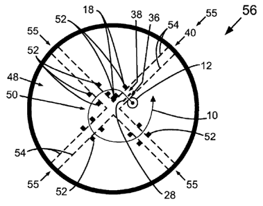
In contrast to the prior art configuration of Figure 2A, Figure 2B shows the
cyclotron 56 according to an embodiment of the invention in which, for
example, the
intermediate electrode 28 is placed between the 'puller' or extraction
electrode 18 and the
ion source 12. The ion source 12 is shown in Figure 2B as being an internal
source
which is internal to the particle accelerator 56 of Figure 2B. In conjunction
with
appropriate separation and applied voltage in accordance with an embodiment of
the
invention, then the focal length can be positive and the particle beam 10 is
focused. The
ability to better focus the beam in accordance with an embodiment of the
invention has
several positive consequences. Beam loss is reduced. Erosion of electrodes by
beam loss
is reduced. Life time of cyclotron components increases because of the
reduction of
beam loss. The total accelerated current increases. The improved focusing of
the beam
10 in accordance with the present invention is represented graphically in
Figure 2B by a
narrow line width of the beam 10.
Figure 2B also shows the first gap 36, between the ion source 12 and the
intermediate electrode 28, and the second gap 38, between the intermediate
electrode 28
and the extraction electrode 18, which together form the dual acceleration gap
40. The
`dee' gaps 55, one of which is the dual acceleration gap 40, between the four
`dee'
sections of the cyclotron 56 are shown in Figure 2B as being bounded by the
dashed lines
54. The extraction electrode 18 may be implemented as electrode posts 52, as
shown in
Figure 2B. While Figure 2B shows four `dee' gaps 55 between four `dee'
sections, the
present invention is suitable for implementation within cyclotrons and other
oscillating
field particle accelerators having any number of `dee' sections and any number
of
electrode posts 52.
While not shown in the Figures, additional or alternative instances of the
intermediate electrode 28 of the present invention may be implemented between
a point
21
CA 02836816 2013-11-20
WO 2012/159212
PCT/CA2012/050336
of entrance of the beam 10 into a given `dee' gap 55 and an electrode post 52
located at
the beam 10 exit from the given `dee' gap 55, thereby forming a dual
acceleration gap 40
configuration in accordance with embodiments of the invention which is
subsequent to
the dual acceleration gap 40 shown in Figure 2B.
Referring back to Figure 2A, another issue in prior art cyclotrons 46 is that
the
time required for charged particles to transit the `dee' gap, including the
single gap 22
(i.e. the time if takes for particles in a beam to reach full energy after
having travelled an
effective distance within the `dee' gap, including the single gap 22) limits
the useable
extraction voltage and as the extracted current is proportional to
(Voltage)3/2, the
maximum current that can be accelerated is correspondingly limited.
Referring again to Figure 2B, the introduction of an intermediate electrode 28
into
a cyclotron 56 in accordance with an embodiment of the invention, for example,
will
result in higher accelerated currents associated with the beam 10 of charged
particles.
Referring back to Figures lA and 2A, in prior art cyclotrons 46 with external
ion
sources (not shown in the Figures), a low energy beam 10 is transported to the
centre or
central region 50 of the prior art cyclotron 46 and bent into the median plane
of the prior
art cyclotron 46 at an appropriate radius and at a position to be accelerated
across a single
gap 22 by a single-gap electric field 24 produced by the extraction electrode
18 which
can be, for example, a radio frequency resonator electrode 18. As with prior
art
cyclotrons 46 (Figure 2A) with internal ion sources 12, the single-gap
electric field 24 in
this single gap 22 is usually enhanced with the use of 'posts' 52 to decrease
the transit
time to higher voltage (i.e. to full energy) of charged particles injected
into the prior art
cyclotron 46. The electrostatic lens formed at this single gap 22 generally
has a negative
focal length in prior art cyclotrons 46, especially prior art cyclotrons 46
with external ion
sources (not shown).
Referring again to Figure 2B, an appropriately designed intermediate electrode
28
in accordance with an embodiment of the invention would advantageously
decrease the
divergence following the acceleration.
22
CA 02836816 2013-11-20
WO 2012/159212
PCT/CA2012/050336
Another potential application of this technique is to the gaps of LINACs (not
shown) accelerating charged particles.
In prior art LINACs (not shown) the particles traverse a linear path in which
the
particles leave a region of negligible electric field, pass through a
collinear gap with high
electric field and enter a collinear region with negligible electric field. It
is well
established and can be calculated for circular apertures, of similar
dimensions, that the
net effect of such linearly extending accelerating gap is weak focusing. Prior
art LINACs
require additional focusing elements to maintain a beam within desired
dimensions.
In contrast to the prior art LINACs and with reference to Figure 1B, the
introduction of an appropriate intermediate electrode 28 in accordance with an
embodiment of the invention in the dual acceleration gap 40 can reduce the
transverse
size of the beam 10 at the final extraction electrode 18 and thereby enhance
the focusing
properties of these dual accelerating gaps 40. The increased focusing would
advantageously reduce the need for as many expensive focusing elements as are
currently
used with existing LINACs and consequently also advantageously reduce the
required
foot print of the LINAC accelerator.
Referring back to Figure 1A, ions or charged particles are accelerated as
beams 10
of particles by particle accelerators. Just as is the case for light beams
where optical
lenses are used to confine photons in the beams to useable dimensions, the
charged
particles in particle beams 10 must be regularly focused with the fields from
magnetic
and electric devices, to confine the particle beams to manageable dimensions.
Ions, or
charged particles, are created in ion sources such as the ion source 12. The
lens
properties of electric and magnetic devices are defined in a manner similar or
analogous
to optics lenses. Ions, or charged particles, are created in ion sources such
as the ion
source 12, extracted from the ion source to form particle beams 10 and then
further
accelerated. When the charged particles are extracted from an ion source 12
with a small
aperture 16 (planar diode) with a single-gap extraction electrode 18, as in
known in the
prior art, the resultant beam 10 is always defocusing (see figure 1A). For
circular
apertures 16 and 20, the focal length (1) can be calculated to be about -4g0,
where g0 is
23
CA 02836816 2013-11-20
WO 2012/159212
PCT/CA2012/050336
the distance between the electrodes 14 and 18 for this geometry. This
divergence
(defocusing because f is always negative for this single-gap electrode
arrangement)
frequently leads to particle beam loss in the accelerator (not shown in Figure
1A).
In contrast to the prior art single-gap configuration of Figure 1A, if an
intermediate electrode 28 as shown in Figure 1B in accordance with an
embodiment of
the invention is placed between the ion source 12 and the final acceleration
(extraction)
electrode 18, and voltages arc applied to the electrodes 28 and 18 and the ion
source wall
14 such that that the first-gap electric field 30 strength (voltage
difference/electrode
separation) between the intermediate electrode 28 and the ion source wall 14
is less than
the second-gap electric field 32 strength between the intermediate electrode
28 and the
extractor or extraction electrode 18, then the beam 10 can advantageously be
focussed or
have reduced defocusing.
Figure 1B shows schematically this type of electrode arrangement in accordance
with an embodiment of the invention. In this case the focal length (with some
simplifying assumptions) can be calculated to be about 4Vf/(Eõit ¨F
_entrance), where Vf is
the voltage gain, Eexit is the electric field in the second gap 38 with a gap
38 distance of
g2, and Eentrance is the electric field at the entrance of the dual
acceleration gap 40 (i.e. in
the first gap 36) having a gap 36 distance of gl . The intermediate electrode
28 position
and voltage can be varied to realize a wide range of ratios for
Eexit/Eentrance, the aperture
dimensions of the ion source aperture 16, intermediate electrode aperture 34
and the
extraction aperture 20 can be arranged to be consistent with beam transverse
dimensions,
and thereby change the focal length from being positive to negative or vice
versa. The
typical cyclotron apertures (not shown in Figure 1B) are rectangular, or
otherwise oblong,
and not circular. The equations for calculating dual-gap focal length in the
case of
rectangular or otherwise oblong apertures are more complicated but the
focusing/defocusing principle remains the same. The structure described above
in
relation to embodiments of the invention shows how intermediate electrodes 28
with
selected voltages applied thereto can be used to manipulate the focal
properties of particle
beams 10 in a variety of different particle accelerators (not shown in Figure
1B),
24
CA 02836816 2013-11-20
WO 2012/159212
PCT/CA2012/050336
including to advantageously reduce beam divergence of beams 10 exiting dual
acceleration gaps 40 as shown in Figure 1B.
As noted above and with reference to Figures IA and 2A, accelerators require
particle beam 10 focusing during the acceleration process to avoid beam 10
loss. In a
particular example, prior art cyclotrons 46 depend on radial (usually
formulated as a
focusing frequency and given the symbol, vr) and vertical focusing (vi) of
particles in the
accelerated beams. At outer regions 48 within a prior art cyclotron 46 where
higher beam
energies occur, the beam 10 focusing in a prior art cyclotron 46 is dominated
by
appropriate variations of the magnetic field and the electric field focusing
is negligible in
10 comparison. However at or near the centre 50 of the prior art cyclotron
46 the radial
focusing from variations of the magnetic field is small and the electric field
focusing
dominates.
Figure 2A schematically shows some of the critical elements found in a prior
art
cyclotron 46 with an internal ion source 12. In prior art cyclotrons 46, the
defocusing
problem is usually reduced with the use of electrode posts 52 (referred to as
a 'puller' or
extraction electrode 52) at the entrance and exit of the 'dee' gap 55 where
the beam 10 is
accelerated. This is valid for both prior art cyclotrons 46 with internal ion
sources 12 and
for prior art cyclotrons 46 with external ion sources (not shown).
Nevertheless, even with
these 'posts' 52, including the extraction electrode 18, the particle beam 10
entering the
`dee' electrode subsequent to exiting the single gap 22 remains radially
defocusing in a
prior art cyclotron 46.
Referring again to Figure 2B, an intermediate electrode 28 in accordance with
an
embodiment of the invention is placed between the 'puller' or extraction
electrode 18 and
the ion source 12 (or inflector for external ion sources, not shown), with
appropriate
separation and applied voltage, then the beam 10 advantageously becomes better
focused.
This technique of embodiments of the invention is suitable for use in
cyclotrons 56 with
internal ion sources 12 and at the early acceleration gaps (e.g. dual
acceleration gaps 40)
for cyclotrons 56 with external ion sources (not shown), for example.
CA 02836816 2013-11-20
WO 2012/159212
PCT/CA2012/050336
Still referring to Figure 2B, the consequences of being able to better focus
the
beam 10 through the puller or extraction electrode 18 in accordance with
embodiments of
the invention are beneficial and numerous. Beam 10 loss is reduced. More
particles are
accelerated. The particle accelerator of the present invention becomes
potentially more
efficient with less induced radio-activity which would otherwise result from
beam 10
loss. Erosion of electrodes 18 by beam 10 loss is reduced. Life time of
cyclotron 56
components increases because of the reduction of beam 10 loss. Beam 10 loss
leads to
activation of components, component heating, surface sputtering, and erosion
of
components with eventual component failure. In brief, the total accelerated
current
increases and the downtime due to beam 10 loss failures decreases.
Referring back to Figures lA and 2A, another issue in prior art cyclotrons 46
is
that the time required for particles to transit the 'dee' gap, including the
single gap 22,
limits the maximum useable extraction voltage and, as the extracted current is
proportional to (Voltage)3/2, the maximum current that can be accelerated is
correspondingly limited under existing schemes.
However, with reference to Figures 1B and 2B, this approach of the present
invention results in the net transit time being advantageously reduced and the
extraction
voltage being advantageously higher. Implementing this invention involves
adding this
intermediate electrode 28 with appropriate voltages and electrode separations
so to
achieve particle beam focusing or reduced defocusing across the dual
acceleration gap
40. The focusing principle is general and, in fact, can be applied to dual
accelerating gaps
40 of particle accelerators other than cyclotrons 56.
Referring back to Figures IA and 2A, the single accelerator gaps 22 used in
prior
art linear accelerators (LINACs) (not shown) do have a weak, net, positive-
focusing
force.
However, referring to Figure 1B, the focusing in a LINAC (not shown) can
advantageously be made stronger with an intermediate electrode 28 in
accordance with an
embodiment of the invention that produces a smaller electric field in the
first gap 36
compared to the electric field in the second gap 38.
26
CA 02836816 2013-11-20
WO 2012/159212
PCT/CA2012/050336
In a first embodiment of the invention and with reference to Figure 1B, an
oscillating field particle accelerator (not shown in Figure 1B) includes an
intermediate
electrode 28 disposed between an internal ion source 12 and an extraction
electrode 18 of
the particle accelerator. The intermediate electrode 28 is formed of a planar
sheet aligned
transversely to the direction of travel of the particle beam 10. There is an
aperture 34 in
the planar sheet through which the particle beam 10 may traverse. The aperture
34 may
be a rectangular slit aperture, or otherwise be oblong in shape, may be
circular or may
have any suitable shape for example. There is a voltage source (not shown)
applied to
the intermediate electrode 28, which may be a fixed, direct current (DC)
voltage or may
be a time-varying voltage. The magnitude of the first-gap electric field 30
between the
ion source 12 and the intermediate electrode 28 is less than the peak
magnitude of the
second-gap electric field 32 between the intermediate electrode 28 and the
extraction
electrode 18. The extraction electrode 18 is disposed further from the ion
source 12 than
is the intermediate electrode 28, thus the extraction electrode 18 is a final
electrode 18.
In a second embodiment of the invention, an oscillating field particle
accelerator
(not shown in Figure 1B) includes a connection to an external ion source (not
shown) and
includes an internal dual acceleration gap 40 having an input end connected to
the
external ion source and an output end defined by a final extraction electrode
18 from
which a particle beam emerges into the remainder (e.g. main body) of the
particle
accelerator. In the second embodiment, an intermediate electrode 28 is
disposed between
the input and output ends of the internal dual acceleration gap 40 such that
the
intermediate electrode 28 is disposed between the connection to the external
ion source
(not shown) and the final electrode 18. The intermediate electrode 28 is
formed of a
planar sheet aligned transversely to the direction of travel of the particle
beam 10. There
is an aperture 34 in the planar sheet through which the particle beam 10 may
traverse.
The aperture 34 may be a rectangular slit aperture, or otherwise oblong in
shape, may be
circular or may have any suitable shape for example. There is a voltage source
(not
shown) applied to the intermediate electrode 28, which may be a fixed, direct
current
(DC) voltage or may be a time-varying voltage. The magnitude of the first-gap
electric
27
CA 02836816 2013-11-20
WO 2012/159212
PCT/CA2012/050336
field 30 between the input end and the intermediate electrode 28 is less than
then the peak
magnitude of the second-gap electric field 32 between the intermediate
electrode 28 and
the output end.
In a third embodiment of the invention analogously represented by Figure 1B, a
linear particle accelerator (LINAC) (not shown) includes a sequence of
longitudinally
aligned tube-like or cylindrical electrodes. The cylindrical electrodes are
longitudinally
spaced apart so as to form linear acceleration gaps between adjacent
electrodes. Charged
particles are accelerated through these acceleration gaps by electric fields
caused by
voltage differences existing between adjacent cylindrical electrodes. In the
third
embodiment, an intermediate electrode, represented by analogy in Figure 1B by
the
intermediate electrode 28, having a ring-like or tube-like structure is placed
within a dual
acceleration gap 40 so as to be longitudinally aligned with, spaced apart
from, adjacent to
and between an initial cylindrical electrode (typically at ground potential),
represented in
Figure 1B by the ion source wall 14, and a final cylindrical electrode
(typically having
applied thereto a time-varying voltage), which is represented in Figure 1B by
the
extraction electrode 18. The ring-like or tube-like structure of the
intermediate electrode
28 defines a ring-shaped or tube-shaped intermediate aperture 34. The
intermediate
aperture 34 may be cylindrical and have a circular cross-section. In the
direction of travel
of the beam particles through the linear accelerator (not shown), each
intermediate
electrode 28 precedes its corresponding final electrode 18 and is disposed
between an ion
source 12 associated with the linear accelerator and its corresponding final
electrode 18.
In the direction of travel of the beam particles through the linear
accelerator, one or more
intermediate electrodes 18 may follow adjacently corresponding initial
electrodes 14.
There is a voltage source applied to the intermediate electrode 28, which may
be a fixed,
direct current (DC) voltage or may be a time-varying voltage. The voltage
applied to the
intermediate electrode 28 causes a first-gap electric field 30 to form between
the
immediately preceding initial electrode 14 and the intermediate electrode 28.
The
magnitude of the first-gap electric field 30 is related to the voltage
difference between the
intermediate electrode 28 and its corresponding initial electrode 14. A second-
gap
28
CA 02836816 2013-11-20
WO 2012/159212
PCT/CA2012/050336
electric field 32 is formed between the intermediate electrode 28 and the
immediately
following final electrode 18, and the magnitude of the second-gap electric
field 32 is
related to the voltage difference between the intermediate electrode 28 and
its
corresponding final electrode 18. The magnitude of the first-gap electric
field 30 is less
than the peak magnitude of the second-gap electric field 32.
Referring to Figures 3 and 4, a sinusoidally time-varying second-gap electric
field
32 is shown in accordance with exemplary embodiments of the invention. The
second-
gap electric field 32 shown in Figures 3 and 4 can be created by applying a
sinusoidally
time-varying voltage to the extraction electrode 18 (Figure 2B) of the dual
accelerating
gap 40 (Figure 2B), for example. In the exemplary embodiment of Figures 3 and
4, and
for ease of discussion, the ion source wall 14 is at ground potential (i.e.
zero volts)
relative to the intermediate electrode 28 (Figure 2B) and the extraction
electrode 18
(Figure 2B).
Figure 3 represents acceleration of negatively charged particles or ions, in
which
the first-gap electric field 30 has a positive value, such as may be caused by
applying a
positive direct current (DC) voltage to the intermediate electrode 28 (Figure
2B). On the
other hand Figure 4 represents acceleration of positively charged particles or
ions, in
which the first-gap electric field 30 has a negative value, such as may be
caused by
applying a negative DC voltage to the intermediate electrode 28 (Figure 2B).
In general,
the ion source wall 14 need not be at ground potential relative to the
intermediate
electrode 28 (Figure 2B) and the extraction electrode 18 (Figure 2B), provided
the
electrical potential of the intermediate electrode 28 is negative relative to
electrical
potential of the ion source wall 14 when accelerating positively charged ions
and positive
when accelerating negatively charged ions.
The exemplary phase acceptance of the embodiment of Figures 3 and 4 is 90
degrees (from -45 degrees to +45 degrees), as shown in Figures 3 and 4 by
dashed lines
58. While Figures 3 and 4 show the phase acceptance time period as being
symmetrical
about the occurrence in each cycle of the peak value 60 of the second-gap
electric field
32, in general the phase acceptance need not be precisely symmetrical with
respect to the
29
CA 02836816 2013-11-20
WO 2012/159212
PCT/CA2012/050336
peak of the second-gap electric field 32 due to phase lagging or phase leading
within the
dual acceleration gap 40 configuration. Phase acceptance values other than 90
degrees
are possible. For example, phase acceptance is typically in the range of 0 to
90 degrees,
and may be in the range o120 to 50 degrees. In some embodiments, the phase
acceptance
may be substantially equal to 36 degrees, which corresponds to a percentage
acceptance
of ten percent of the 360 degree cycle.
In the exemplary embodiments shown in Figures 3 and 4, the magnitude of the
first-gap electric field 30 is equal to the minimum magnitude of the second-
gap electric
field 32 occurring during the phase acceptance time period associated with the
phase
acceptance shown in Figures 3 and 4. In variations of embodiments, the first-
gap electric
field 30 may have a magnitude which is less than (i.e. closer to zero) than
the magnitudes
of the second-gap electric field 32 for which charged particles will be
accepted into the
main body of the particle accelerator. Reducing the magnitude of the first-gap
electric
field 30 relative to the magnitude of the second-gap electric field 32
advantageously
increases the focusing and/or decreases the defocusing of the beam 10 of
charged
particles. However, such reduction in the magnitude of the first-gap electric
field 30 can
cause a reduction in beam 10 current entering the main body of the particle
accelerator.
Thus, for some embodiments of the invention an optimal magnitude of the first-
gap
electric field 30 is equal to the minimum phase acceptance magnitude of the
second-gap
electric field 32.
Further optimization of embodiments of the invention may be achieved by
implementing a time-varying first-gap electric field 30, albeit with the
possibility of
introducing additional variability in the beam 10 current of the beam 10
entering the main
body of the particle accelerator. For example, a first-gap electric field 30
magnitude
having a waveform offset from or otherwise corresponding to the second-gap
electric
field 32 magnitude waveform during phase acceptance can result in desired
focusing
characteristics of the beam 10 during phase acceptance. By way of example, a
first-gap
electric field 30 magnitude which is less than the second-gap electric field
32 magnitude
by a constant offset magnitude during phase acceptance such that their
respective
CA 02836816 2013-11-20
WO 2012/159212
PCT/CA2012/050336
waveform shapes match (not shown) during phase acceptance, albeit with an
appropriate
phase offset to account for beam 10 transit time through the dual acceleration
gap 40
(Figure 28), will advantageously result in a constant amount of focusing
and/or a
constant amount of the reduction in defocusing.
Referring to Figures 5A and 5B, comparative simulations of beam 10 dynamics
have been performed by the inventor of the present invention and comparative
simulation
results are shown.
Figure 5A shows a plan view of a portion of a simulated prior art cyclotron 46
in
which an ion source 12 and extraction electrode 18 form an initial
acceleration single gap
22. Upon exiting the single gap 22, the beam 10 diverges such that a portion
of the beam
10 is thereafter blocked when passing a first of subsequent pairs of electrode
posts 52
associated with a first subsequent `dee' gap 55, such that only a limited and
small beam
10 current is able to pass into the main body (not shown in Figure 5A) of the
prior art
cyclotron 46. When Figure 5A shows divergence of the beam 10 in the plan view,
a
similar divergence occurs in the transverse plane as could be seen in a side
view (not
shown).
Figure 5B shows a plan view of a portion of a simulated cyclotron 56 having
the
intermediate electrode 28 positioned between the ion source 12 and the
extraction
electrode 18, thereby forming the first gap 36 and the second gap 38 of the
dual
acceleration gap 40 configuration. Upon exiting the dual acceleration gap 40
configuration, the beam divergence is reduced such that less or no portion of
the beam 10
is blocked by the first subsequent pair of electrode posts 52 associated with
the first
subsequent 'dee' gap 55, thereby permitting a larger beam 10 current to pass
into the
main body of the cyclotron 56. While Figure 5B shown reduced divergence of the
beam
10 in the plan view in accordance with embodiments of the invention, a similar
reduction
in divergence occurs in such embodiments in the transverse plane as could be
seen in a
side view (not shown).
Thus, there is provided an oscillating field particle accelerator for
accelerating
charged particles, the particle accelerator comprising an intermediate
electrode disposed
31
CA 02836816 2013-11-20
WO 2012/159212
PCT/CA2012/050336
within the particle accelerator between a source of the charged particles and
a second
electrode of the particle accelerator, the charged particles being exposed to
a first electric
field extending between said source and said intermediate electrode prior to
being
exposed to a second electric field extending between said intermediate
electrode and said
second electrode, the magnitude of said first electric field being less than a
peak
magnitude of said second electric field.
Method of Operation
With reference to Figures 1B, 2B, 3, 4 and 5B and the first embodiment of the
invention, the internal ion source 12 produces ions or charged particles that
form a
particle beam 10. Particles of the beam 10 are accelerated through a first
region, such as
the first gap 36 shown in Figures 1B, 2B and 5B, defined between the ion
source 12 and
the intermediate electrode 28, by a first-gap electric field 30 present in the
first gap 36.
The first-gap electric field 30 is caused by a voltage applied to the
intermediate electrode
28 such that a potential difference between the ion source wall 14 and the
intermediate
electrode 28 is created. At least some of thc beam 10 particles pass from the
first gap 36
through an aperture 34 in the intermediate electrode 28 into a second region,
such as the
second gap 38 shown in Figures 1B, 2B and 5B, defined between the intermediate
electrode 28 and the extraction electrode 18. There is a second-gap electric
field 32 in
the second gap 38 which is caused by a voltage applied to the extraction
electrode 18
such that a potential difference between the intermediate electrode 28 and the
extraction
electrode 18 is created. The beam 10 particles passing into the second gap 38
are
accelerated by the second-gap electric field 32. At least some of the beam 10
particles
accelerated in the second gap 38 pass through an aperture 20 of the extraction
electrode
18 to emerge into the remainder of the particle accelerator as an extracted
particle beam
10. By appropriately setting the voltage applied to the intermediate electrode
28 and the
relative separation distances of the first and second gaps 36 and 38,
divergence of the
extracted beam 10 can be reduced or eliminated, including causing the
extracted beam 10
32
CA 02836816 2013-11-20
WO 2012/159212
PCT/CA2012/050336
to converge.
With reference to Figures 1B, 2B, 3, 4 and 5B and the second embodiment of the
invention, the external ion source (not shown) produces ions or charged
particles that
form a particle beam 10. Particles of the beam 10 are received into the
particle
accelerator via a connection between the external ion source and the particle
accelerator.
Particles of the received beam 10 are accelerated through a first region, such
as the first
gap 36 shown in Figures 1B, 2B and 5B, defined between the ion source 12 and
the
intermediate electrode 28, by a first-gap electric field 30 present in the
first gap 36, in a
manner analogous to that of the first embodiment. The remainder of the
operation of the
second embodiment of the invention is identical, similar or analogous to that
of the
corresponding operation of the first embodiment.
With reference to Figures 1B, 2B, 3, 4 and 5B and the third embodiment of the
invention, the ion source associated with the linear accelerator (not shown)
is typically an
external ion source (not shown) that produces ions or charged particles in the
form of a
particle beam 10 received into the longitudinal chamber of the linear
accelerator.
Particles of the beam 10 are successively accelerated in longitudinally
aligned
acceleration gaps which, in the third embodiment, arc configured as dual
acceleration
gaps 40 having an intermediate electrode 28. Within each dual acceleration gap
40 of the
third embodiment, beam 10 particles entering the acceleration gap are
accelerated
through a first region, such as the first gap 36 shown in Figures 1B, 2B and
5B or another
first gap analogous thereto, defined adjacent to and preceding the aperture of
the ring-like
or tube-like intermediate electrode 28 by a first-gap electric field 30 caused
by an
intermediate electrode 28 voltage applied to the intermediate electrode 28,
and then
accelerated through a second region, such as the second gap 38 shown in
Figures 1B, 2B
and 5B or another second gap analogous thereto, defined adjacent to and
following the
aperture 34 of the intermediate electrode 28 by a second-gap electric field 32
caused by
the final extraction electrode 18, before exiting the dual acceleration gap 40
into a
subsequent non-acceleration region.
Accordingly in embodiments of the invention, the oscillating field particle
33
CA 02836816 2013-11-20
WO 2012/159212
PCT/CA2012/050336
accelerator receives ions or charged particles in the form of a particle beam
from an ion
source, passes the beam particles through a first electric field caused by an
intermediate
electrode of the particle accelerator, and then passes the beam particles
through a second
electric field caused by an electrode of the particle accelerator such that
the particle beam
emerging from the second electric field region is of reduced divergence or is
a non-
diverging particle beam, including a converging particle beam.
Thus, there is provided a method of reducing divergence of a beam of charged
particles in an oscillating field particle accelerator, the method comprising
passing the
charged particles through a first electric field from a source of the charged
particles
toward an intermediate electrode disposed within the particle accelerator and
then passing
the charged particles through a second electric field from said intermediate
electrode
toward a second electrode of the particle accelerator when the magnitude of
said first
electric field is less than a peak magnitude of said second electric field.
While embodiments of the invention have been described and illustrated, such
embodiments should be considered illustrative of the invention only. The
invention may
include variants not described or illustrated herein in detail. For example,
the material of
the intermediate electrode may be selected for achieving desired
characteristics of the
particle beam passing through the intermediate electrode or aperture thereof,
including
selecting the intermediate electrode material to be an electrically conductive
material.
Thus, the embodiments described and illustrated herein should not be
considered to limit
the invention as construed in accordance with the accompanying claims.
34