Note: Descriptions are shown in the official language in which they were submitted.
CA 02837029 2013-12-17
REMOVAL OF ARTIFACTS FROM MAP DATA
FIELD OF THE INVENTION
The present invention relates generally to
measurements of physical parameters, and specifically to
measurements of parameters associated with a body organ
such as the heart.
BACKGROUND OF THE INVENTION
In medical procedures, such as mapping the
electrical activity of the heart, the measurements are
typically relatively noisy. A system to reduce the effect
of the noise on the measurements would be beneficial.
1
CA 02837029 2013-12-17
SUMMARY OF THE INVENTION
An embodiment of the present invention provides a
method for mapping, including:
receiving an initial set of measured values of a
physiological parameter, which were measured at
respective locations in a body organ;
receiving a three-dimensional (3D) map of the organ
comprising an array of spatial map elements;
forming a correspondence between the respective
locations at which the measured values were measured and
a sub-group of the map elements;
in response to the correspondence, associating
respective element values of the physiological parameter
with map elements other than the sub-group;
adjusting the respective element values so that
contiguous sets of the map elements form a geodesic; and
displaying a map of the organ showing the adjusted
element values.
In one embodiment the body organ includes a heart,
and the physiological parameter consists of a local
activation time of the heart.
Typically, the spatial map elements include planar
polygons having vertices corresponding to positions on a
wall of the body organ. In a disclosed embodiment the
planar polygons include triangles, and the sub-group
includes respective nearest triangles to the respective
locations. The map elements other than the subgroup may
include one or more adjacent triangles having a common
side with each of the respective nearest triangles.
The method may further include identifying the one
or more adjacent triangles in response to a slowness
2
CA 02837029 2013-12-17
,
vector associated with each of the respective nearest
triangles.
Adjusting the respective element values may include
adjusting element values of centroids of a given nearest
triangle and of the one or more triangles adjacent to the
given nearest triangle to form the geodesic.
Alternatively or additionally, adjusting the respective
element values may include minimizing localized
displacement vectors associated with the centroids.
In an alternative embodiment the map elements other
than the subgroup include one or more triangles not
having a common side with each of the respective nearest
triangles.
In a further alternative embodiment the geodesic
includes a spatial geodesic.
In a yet further alternative embodiment displaying
the map includes incorporating isochronal lines
associated with the organ into the map.
In a further disclosed embodiment the geodesic
includes a temporal geodesic.
Receiving the initial set of measured values may
include simultaneously receiving a plurality of measured
values of the physiological parameter from a plurality of
respective electrodes at the respective locations.
There is further provided, according to an
embodiment of the present invention, apparatus for
mapping, including:
a probe configured to:
generate an initial set of measured values of a
physiological parameter, which were measured at
respective locations in a body organ, and
3
CA 02837029 2013-12-17
generate a three-dimensional (3D) map of the organ
comprising an array of spatial map elements; and
a processor, configured to:
form a correspondence between the respective
locations at which the measured values were measured and
a sub-group of the map elements,
in response to the correspondence, associate
respective element values of the physiological parameter
with map elements other than the sub-group,
adjust the respective element values so that
contiguous sets of the map elements form a geodesic, and
display a map of the organ showing the adjusted
element values.
The present disclosure will be more fully
understood from the following detailed description of the
embodiments thereof, taken together with the drawings, in
which:
4
CA 02837029 2013-12-17
BRIEF DESCRIPTION OF THE DRAWINGS
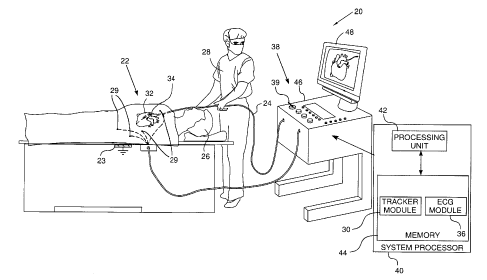
Fig. 1 is a schematic illustration of an
electrophysiological signal analysis system, according to
an embodiment of the present invention;
Fig. 2 is a schematic diagram illustrating a three-
dimensional map of interior walls of a heart, according
to an embodiment of the present invention;
Figs. 3A and 3B are schematic diagrams of three
triangles in the map of Fig. 2, according to an
embodiment of the present invention;
Fig. 4 is a flowchart of steps performed by a
processor, in calculating estimated local activation
times in a heart, according to an embodiment of the
present invention; and
Fig. 5 shows schematic illustrations of isochronal
lines, according to an embodiment of the present
invention.
5
CA 02837029 2013-12-17
DETAILED DESCRIPTION OF EMBODIMENTS
OVERVIEW
An embodiment of the present invention provides a
method for mapping a physical parameter associated with a
body organ. Typically, and as assumed herein, the body
organ is the heart of a subject, and the physical
parameter comprises local activation times (LATs)
associated with the beating of the heart. The LAT is an
indication of the flow of electrical activity through
walls of the heart, and embodiments of the present
invention use an initial set of measured values of the
LATs.
A correspondence is formed between the initial set
of LATs and a sub-group of spatial map elements,
typically polygonal elements in the form of a mesh, of
the heart wall. Except where otherwise stated, in the
following description the polygonal spatial map elements
are assumed to comprise triangular elements. The spatial
map elements, including the sub-group, may be generated
from measured positions of the heart wall.
Once the correspondence has been performed, LATs
associated with map elements other than those of the sub-
group, i.e., with triangles apart from the sub-group of
triangles, are estimated. The estimated LAT values may be
adjusted so that centroids of the triangles associated
with the LATs, typically including triangles included in
the sub-group, form a geodesic. The geodesic is typically
a spatial geodesic, wherein distances are minimized. In
some embodiments the geodesic comprises a temporal
geodesic, in which case the measured times between LATs
6
CA 02837029 2013-12-17
of the centroids are minimized. The estimation process
typically forms multiple geodesics.
Once the LATs have been adjusted to form the
multiple geodesics, the LATs may be sorted to generate
isochrones. A map of the heart, typically based on the
mesh described above, may be displayed showing the
adjusted LATs in the form of isochronal lines.
Adjusting the LATs so that they form a geodesic on a
map of the heart wall allows the LATs to be smoothed in
relation to positions of sections of the heart wall. The
inventors have found that such smoothing gives superior
results compared to smoothing by prior art methods.
SYSTEM DESCRIPTION
Reference is now made to Fig. 1, which is a
schematic illustration of an electrophysiological signal
analysis system 20, according to an embodiment of the
present invention. System 20 may be configured to analyze
substantially any physiological parameter or combinations
of such parameters, but in the description herein, by way
of example, the signals analyzed are assumed to be intra-
cardiac electrocardiogram (ECG)
potential-time
relationships. In order to fully characterize such
relationships, the signals need to be referenced in time
to each other.
In embodiments of the present invention, the time
referencing is accomplished by measuring to an instance
in time, herein termed the reference instance, on a
reference signal. Herein, by way of example, the
reference signal is assumed to comprise a reference ECG
potential vs. time signal. Also by way of example, the
reference instance is assumed to be the beginning of the
7
CA 02837029 2013-12-17
QRS complex of the ECG reference signal. For any given
location in the heart being mapped, a physical parameter
termed a local activation time (LAT) of the electrical
activity of the location may be defined in terms of the
electrical activity satisfying a predefined condition.
In the following description, the predefined
condition is assumed to comprise a time of occurrence of
the largest rapid change of potential at the location,
and the LAT is assumed to be the time from the reference
instance to the following onset of the largest rapid
potential deflection at the location. LATs may be
positive or negative. Methods for determining the time of
occurrence of the largest rapid potential deflection, and
other definitions and conditions for determining the LAT,
will be familiar to those skilled in the art, and all
such methods, definitions, and conditions are assumed to
be comprised within the scope of the present invention.
For simplicity and clarity, the following
description, except where otherwise stated, assumes an
investigative procedure wherein system 20 senses
electrical signals from a heart 34, using a probe 24. A
distal end 32 of the probe is assumed to have an
electrode 22. Those having ordinary skill in the art will
be able to adapt the description for multiple probes
having one or more electrodes, as well as for signals
produced by organs other than a heart.
Typically, probe 24 comprises a catheter which is
inserted into the body of a subject 26 during a mapping
procedure performed by a user 28 of system 20. In the
description herein user 28 is assumed, by way of example,
to be a medical professional. During the procedure
8
CA 02837029 2013-12-17
subject 26 is assumed to be attached to a grounding
electrode 23. In addition, electrodes 29 are assumed to
be attached to the skin of subject 26, in the region of
heart 34.
System 20 may be controlled by a system processor
40, comprising a processing unit 42 communicating with a
memory 44. Processor 40 is typically mounted in a console
46, which comprises operating controls 38, typically
including a pointing device 39 such as a mouse or
trackball, that professional 28 uses to interact with the
processor. The processor uses software, including a probe
tracker module 30 and an ECG module 36, stored in memory
44, to operate system 20. Results of the operations
performed by processor 40 are presented to the
professional on a display 48, which typically presents a
graphic user interface to the user, a visual
representation of the ECG signals sensed by electrodes
22, and/or an image or map of heart 34 while it is being
investigated. The software may be downloaded to processor
40 in electronic form, over a network, for example, or it
may, alternatively or additionally, be provided and/or
stored on non-transitory tangible media, such as
magnetic, optical, or electronic memory.
ECG module 36 is coupled to receive electrical
signals from electrodes 22 and electrodes 29. The module
is configured to analyze the signals and may present the
results of the analysis in a standard ECG format,
typically a graphical representation moving with time, on
display 48.
Probe tracker module 30 tracks sections of probe 24
while the probe is within subject 26. The tracker module
9
CA 02837029 2013-12-17
typically tracks both the location and orientation of
distal end 32 of probe 24, within the heart of subject
26. In some embodiments module 30 tracks other sections
of the probe. The tracker module may use any method for
tracking probes known in the art. For example, module 30
may operate magnetic field transmitters in the vicinity
of the subject, so that magnetic fields from the
transmitters interact with tracking coils located in
sections of the probe being tracked. The coils
interacting with the magnetic fields generate signals
which are transmitted to the module, and the module
analyzes the signals to determine a location and
orientation of the coils. (For simplicity such coils and
transmitters are not shown in Fig. 1.) The Carto system
produced by Biosense Webster, of Diamond Bar, CA, uses
such a tracking method. Alternatively or additionally,
tracker module 30 may track probe 24 by measuring
impedances between electrode 23, electrodes 29 and
electrodes 22, as well as the impedances to other
electrodes which may be located on the probe. (In this
case electrodes 22 and/or electrodes 29 may provide both
ECG and tracking signals.) The Carto3 system produced by
Biosense Webster uses both magnetic field transmitters
and impedance measurements for tracking.
Using tracker module 30 processor 40 is able to
measure locations of distal end 32. In addition, using
both tracker module 30 and ECG module 36 the processor is
able to measure locations of the distal end, as well as
LATs of the signals detected at these particular
locations. For clarity, in the present disclosure and in
the claims, measured locations of the distal end that do
CA 02837029 2013-12-17
not have associated LAT measurements are herein termed
non-LAT-locations, and measured locations of the distal
end having respective LAT measurements are termed LAT-
locations. In embodiments of the present invention, non-
LAT-locations are assumed to be used to generate a three-
dimensional (3D) anatomic map of walls of heart 34.
Fig. 2 is a schematic diagram 60 illustrating a 3D
map 62 of interior walls of heart 34, as well as LAT-
locations, according to an embodiment of the present
invention. Diagram 60 may be presented on display 48. For
simplicity, only a portion of a complete map is shown in
Fig. 2. Map 62 is formulated as a mesh comprising a
multitude of non-LAT-location points 64, the positions of
which have been evaluated by tracker module 30. The heart
wall is moving, but in the evaluation of the positions of
the non-LAT-location points, the module allows for such
movement, for example by adjusting all measured points to
a reference time during a heartbeat, such as the
initiation of atrial systole. By methods known in the
art, processor 40 connects points 64 by straight inter-
point lines 66 so as to form a mesh of connected planar
polygons. The planar polygons may have any convenient
numbers of sides, and for example may comprise pentagons,
or hexagons. For simplicity, in the following description
the connected planar polygons are assumed to comprise
triangles 70, and those having ordinary skill in the art
will be able to adapt the description for the case of
planar polygons having other than three sides. Connected
triangles 70 form a surface that approximates to the
heart interior wall surface.
The diagram also shows LAT-locations 68, each LAT-
11
CA 02837029 2013-12-17
location having an associated LAT. Typically, LAT-
locations and their associated LATs are evaluated at a
different time period from the time used by processor 40
to generate map 62. (In presenting diagram 60 on display
48, the value of the LAT associated with a given LAT-
location may be indicated by color-coding the dots
representing the LAT-locations.) In the present
disclosure, and as required, specific non-LAT-locations
64, lines 66, and LAT-locations 68 are distinguished by
adding reference letters as a suffix and/or prefix to the
identifying numeral. For example, in diagram 60, three
non-LAT-locations 64D, 64E, 64F, form a triangle 70D, and
an LAT-location 68D is close to, but separate from,
triangle 701J.
As for non-LAT-locations, LAT-locations are adjusted
to the reference time. In principle, LAT-locations 68
should be in registration with surfaces of triangles 70,
since both types of locations, LAT-locations and non-LAT-
locations, should lie on the heart wall. In practice,
however, the locations are not in registration, due for
example, to errors in measurements of the locations, and
to errors in adjusting the measured locations. The errors
are typically at least partially due to the heart's
movement. Embodiments of the present invention correct
for the mis-registration of the two types of locations.
Figs. 3A and 33 are schematic diagrams of three
triangles 70A, 70B, 70C in map 62, according to an
embodiment of the present invention. The diagrams are
drawn with reference to a set of orthogonal xyz axes, so
that Fig. 3B is a side view of the three triangles, and
Fig. 3A is a top view. Triangle 70A has as vertices non-
12
CA 02837029 2013-12-17
LAT-locations 64L, 64M, 64N, the vertices being connected
by lines 66L, 66M, 66N. Triangle 70B has as vertices non-
LAT-locations 64P, 64M, 64N, connected by lines 66Q, 66M,
66P. Triangle 70C has as vertices non-LAT-locations 64L,
64M, 64Q, connected by lines 66L, 66Q, 66S. Vertices 64M,
64N and line 66M are common to triangles 70A, 70B, and
vertices 64M, 64L and line 66L are common to triangles
70A, 70C. By way of example the xyz orthogonal axes are
assumed to have the z-axis parallel to line 66M, and to
be configured so that triangle 70A lies in a plane 72
parallel to the xz plane. An LAT-location 683 is close to
triangle 70A, and is not in plane 72.
Triangle 70A has a geometric centroid C70A, triangle
70B has a geometric centroid C70B, and triangle 70C has a
geometric centroid C70C. It will be understood that
centroids C70A, C70B, C70C may be calculated from known
values of the vertices of respective triangles 70A, 70B,
70C. Other elements of Figs. 3A and 33 are described
below.
The electrical activity of the heart may be thought
of as a potential which initiates, at the beginning of
every heart beat, at the sinus node, and which flows
through the cardiac muscle and connective tissue
comprising the heart. At any point on a cavity wall of
the heart, an LAT at that point is caused by the
potential flowing passed the point. As explained above,
mesh 62 approximates to the wall of the heart.
Embodiments of the present invention generate estimates
of LATs at points on heart cavity walls, using measured
LAT-locations and their associated values of LAT,
together with measured non-LAT-locations, by estimating
13
CA 02837029 2013-12-17
flows of the electrical activity through mesh 62, and
LATs at centroids of triangles of the mesh, as described
below.
Fig. 4 is a flowchart 100 of steps performed by
processor 40, in calculating estimated LATs in heart 34,
according to an embodiment of the present invention.
In a mapping step 102, the processor and tracker
module 30 receive and acquire 3D values of non-LAT-
locations 64. The reception and acquisition may be
accomplished by moving distal end 32 of probe 24 until
the distal end contacts the heart wall.
In a mesh generating step 104, the processor
connects non-LAT-locations 64 with straight lines, so as
to form mesh 62. Mesh 62 is formed as an array of spatial
map elements comprising triangles 70. Methods of forming
a mesh of triangular elements from a set of 3D points are
known in the art, and typically comprise joining any
given point to one or more of its nearest neighbors.
In a centroid step 106, the processor calculates the
value of respective centroids of each of the mesh
triangles.
In a "raw" LAT step 108, processor 40, using tracker
module 30 and ECG module 36, receives and acquires sets
of LAT-locations 68, and their associated LATs. The
acquisition is substantially similar to the acquisition
of non-LAT-locations 64 (step 102), but typically the
dwell time of distal end 32 at each LAT-location 68 is
longer than the times at non-LAT-locations, to allow the
processor to acquire the LAT of the location.
Steps 102 and 108 are independent of each other.
Thus, the steps may be performed one after the other, or
14
CA 02837029 2013-12-17
alternatively they may be performed substantially
simultaneously.
In the remaining steps of flowchart 100, the
processor performs calculations on substantially all
triangles 70 of mesh 62, and on substantially all LAT-
locations 68. For clarity, the explanation of the steps
refers to triangles 70A, 70B, and 70C of Figs. 3A and 3B.
In a projection step 110, the processor determines
the closest triangle 70 to, i.e., in correspondence with,
each LAT-location 68. Such triangles are herein termed
base triangles. Once the base triangle for a given LAT-
location 68 has been determined, the processor projects
the LAT-location onto the base triangle at an LAT-
projection point. Thus, referring to Fig. 3A, processor
40 determines that triangle 70A is closest to LAT-
location 68B, and so triangle 70A is a base triangle. The
processor projects LAT-location 68B to an LAT-projection
point P68B on base triangle 70A.
In an adjacent triangle step 111, the processor
determines triangles that are adjacent, i.e., contiguous
with, the base triangles located in step 110.
In a y and LAT assignment step 112, for each base
triangle element in the mesh, i.e., each triangle having
an LAT-projection point, the processor assigns a map
element value, herein assumed to comprise a centroidal
local activation time, according to equation (1):
ti--)/id 'Tk Et (1)
where t is the assigned local activation time (LAT)
of the centroid of the base triangle,
i is an identifier of the base triangle,
CA 02837029 2013-12-17
T is the LAT of the LAT-location,
k is an identifier of the LAT-location,
Et is a constant that is a measure of the similarity
of the measured LAT-value (T1) and the desired value LAT
ao in a triangle centroid. Et can be preset as a small
random value, typically in a range +(-0.01-0.05) ms, and
Tki is a parameter.
This equation will be used in step 119.
The parameter yki is typically in a range from 0 -
1, and the value of the parameter may be adjusted, as
explained below, by processor 40. Typically, the value of
the parameter is set closer to 1 as the distance between
the LAT-location and the centroid decreases.
In one embodiment, an exponential function may be
used to formulate a pre-set value for parameter loci,
according to equation (la):
- a= d(i,k)
Yki = e (la)
where a is a scaling constant, and
d(i,k) is a distance between the ith centroid and
the kth LAT location.
For the triangles illustrated in Figs. 3A and 3B,
triangle 70A is a base triangle, and equation (1)
becomes:
t70A =:)/6813,70B.T6813 (lb)
16
CA 02837029 2013-12-17
Equation (1) may be considered to be derived from
measurements made by a single electrode 22 on probe 24. A
more general case (in which equation (1) is included) is
the case where LATs are measured simultaneously by M
multiple electrodes 22 on probe 24, where M is a positive
integer. For such a general case equation (lc) applies:
A
ti+m ¨ (, _L
yki ' Lakm) = Et (lc)
where t, i, T, Et, and k are as defined above for
equation (1),
m is an electrode number, 1 s m 5 M, and
Akm is a time delay of the mth electrode at the kth
LAT-location.
In equation (lc), parameter ykiis common for all m
simultaneously measured points. In an embodiment a value
of the parameter yki may be calculated as an average, or
as a weighted average, of the individual parameter values
given by equation (1d):
-a=d(i+m,m)
Yk,i[1111 e (1d)
where a is as defined above for equation (la), and
d(i+m,m) is a distance between the (i+m)th centroid
and the mth electrode location for the kth measurement.
For simplicity, the following description assumes
that equations (1) and (la), for the case of measurements
being made by a single electrode, apply. Those having
17
CA 02837029 2013-12-17
ordinary skill in the art will be able to adapt the
description for the case covered by equations (lc) and
(1d), i.e. for multiple electrodes making measurements
simultaneously.
In a geodesic step 117, processor 40 calculates a
spatial geodesic A between a base triangle centroid and
an adjacent triangle centroid. The processor performs
this calculation for all triangles in the mesh. The
spatial geodesic minimizes the displacement between two
centroids, and spatial geodesic A may be defined
according to equation (2):
= Min(di + =
di) (2)
-4
where di, di are localized displacement vectors,
respectively from the base and adjacent triangle
centroids to the line common to the two triangles; the
two vectors have a common vertex on the common line.
In the disclosure and in the claims, a geodesic
between elements is to be understood as the shortest path
between the elements, and a geodesic transfer is the
transfer of a parameter along such a path. A geodesic may
be a spatial geodesic, in which case the shortest path is
the shortest spatial path between the elements. Equation
(3) is an example using a spatial geodesic. Alternatively
a geodesic may be a temporal geodesic, in which case the
shortest path is the shortest temporal path between the
elements.
-4
Exemplary localized displacement vectors dm, dm,
18
CA 02837029 2013-12-17
between centroids C7OB and C70A, are illustrated in Fig.
3A, and have a common vertex 76 on line 66M. (For
clarity, the displacement vectors between centroids C70A
and C70C, having a common vertex on line 66L, are not
drawn in the figure.)
In an LAT and slowness estimation step 119, for all
triangles (base and adjacent, i.e., those identified in
steps 110, 111), the processor calculates a slowness
¨0
vector SI to be assigned to respective centroids of the
triangles. The slowness value can be defined according to
relation (3):
V,
S = = (3)
1 Ivii2
where 1/1 is an estimated velocity vector, measuring
a speed and a direction, of the flow of electrical
activity in the ith base triangle.
As is apparent from equation (3), slowness is a
vector having a magnitude that is the reciprocal of the
speed, and a direction that is the same as the velocity
direction.
An exemplary slowness vector SmA, connected to
centroid C70A, is illustrated in triangle 70A.
In step 119, processor 40 uses equation (4) below to
calculate slowness vectors for all triangles.
19
CA 02837029 2013-12-17
S1-S=Es (4)
where i is an identifier of one triangle,
j is an identifier of a triangle that is bordering
triangle i, and
Es is a constant vector that is a measure of the
similarity of slowness values of neighboring locations;
lEsi O. Typically, Kil is approximately 0.01% - 1% of the
expected value of the slowness.
A value of Es may be provided to the processor by
user 28, and may apply for all mesh 62. In some
embodiments, different values of Es may be provided
typically on the basis of where in relation to elements
of the heart triangles i,j are.
S70B, connected to centroid C70B, illustrates an
exemplary triangle slowness vector.
Also in step 119, for each base triangle, processor
40 uses equation (1) above to calculate the assigned
local activation time (LAT) of the centroid of the base
triangle
The processor calculates activation times to be
assigned to the triangle centroids, according to equation
(5) below.
ti - ti = SI = i + Si . i
-4 -d --+ 11 (5)
where i is an identifier of a pre-cursor triangle,
j is an identifier of a triangle bordering pre-
cursor triangle i, i.e., a post-cursor triangle,
CA 02837029 2013-12-17
ti, tj are respective local activation times (LATs)
of centroids of the i and j triangles,
S1 ,S1 are slowness vectors of the i and j
triangles, and
-4 ¨=
di, di are generated from equation (2). Inspection of
the right side of equation (5) indicates that the first
term equals the time of travel of the component of the
electrical activity in the pre-cursor triangle, from the
common triangle line to the pre-cursor triangle centroid.
Similarly, the second term equals the time of travel of
the electrical activity in the post-cursor triangle,
between the common triangle line and the post-cursor
triangle centroid.
Processor 40 applies equation (5) to connect values
of tj and SJ, both for the pre-cursor triangle centroid,
and for the post-cursor triangle centroid. The
application of equation (5) is implemented for all base
and conjugate triangles, so generating activation times
and slownesses for all triangles determined steps 110 and
It will be understood that application of equation
(5) assumes a geodesic transfer of electrical activity
between all triangle centroids of the zone of interest.
In a continuation step 122, the process of
calculating di is extended by performing the calculation
for triangles contiguously surrounding the zone of
interest. Each pre-cursor triangle typically has one or
more further pre-cursor triangles associated with it, the
further pre-cursor triangles forming a contiguous
21
CA 02837029 2013-12-17
sequence of pre-cursor triangles. The identification of
the further pre-cursor triangles may be implemented by
analyzing the sides intersected by the slowness vectors.
Similarly, each post-cursor triangle may have one or
more further post-cursor triangles associated with it,
the further post-cursor triangles also forming a
contiguous sequence of post-cursor triangles.
For example, in Fig. 3A, slowness vector S7013,
intersects side 66P, so that there is a further pre-
cursor triangle (not shown) having a common side 66P with
triangle 70B. Similarly, the slowness vector (not shown)
attached to centroid C70C intersects either side 66R or
66S, so there is a further post-cursor triangle, having
one of these sides as a common side with triangle 70C.
The two sequences may be considered to start from
one base triangle, and all centroids of the triangles in
the path formed by the two sequences lie on a spatial
geodesic.
In step 122, the processor applies the actions of
step 111 to identify further adjacent triangles. As each
further adjacent triangle is identified, the processor
applies the actions of step 117. The processor continues
the generation of adjacent triangles and their activation
times until either an edge of mesh 62, or a triangle on
another geodesic, is encountered.
The actions up to and including step 122 generate a
set of spatial geodesics. Each geodesic comprises a group
of contiguous triangles that are connected to form a path
taken by the flow of electrical activity being mapped.
Typically, once step 122 has completed, there may
remain triangles of mesh 62 that are not on identified
22
CA 02837029 2013-12-17
geodesics, and so do not have assigned activation times.
In a step 124, the processor calculates activation
times and slownesses for adjacent triangles found after
implementation of step 122. The activation times and
slownesses are calculated by solving the system of
equations (4) and (5) for these triangles and using the
already determined activation times and slownesses found
in step 119 for triangles bordering the zone of interest.
In a final step 128, the processor displays the
activation times, and/or the slowness vectors, of the
centroids of triangles of mesh 62, on display 48.
Typically, the smoothed isochronal lines are incorporated
into the display.
By reviewing the description of flowchart 100 it
will be understood that equations presented above
(equations (1), (4) and (5)) are not independent, and
cannot be solved sequentially.
Fig. 5 shows schematic illustrations of isochronal
lines, according to an embodiment of the present
invention. A diagram 150 shows isochronal lines generated
from local activation times generated as described above
for step 108. The lines are drawn using only the measured
LATs, with minimal interpolation and extrapolation. A
diagram 152 shows isochronal lines generated according to
flowchart 100, as applied to the same LATs used for
diagram 150. For clarity, the isochronal lines are
separated by different gray levels, indicative of the
different times associated with the lines. As is evident
from diagram 152, the isochronal lines in diagram 152 are
considerably smoother than those of diagram 150.
While the description above has been generally
23
CA 02837029 2013-12-17
directed to having system 20 analyze and adjust local
activation times, it will be understood that the analysis
and adjustments described above may be applied to other
physiological parameters associated with an organ such as
the heart. For example, rather than operating with times,
system 20 may be configured to operate with voltages
traversing an organ. As another example, there is heat
flow during ablation of an organ, and the heat flow
through the organ may manifest itself as temperature
changes of the organ. System 20 may be configured to
analyze and adjust measured temperatures of the organ.
Those having ordinary skill in the art will be able to
identify other physiological parameters that system 20 is
applicable to, such as the infra-red radiation from an
organ as it functions, and all such parameters are
assumed to be included in the scope of the present
invention.
In addition, while the description above has assumed
that the geodesic transfer of electrical activity
comprises transfer via spatial geodesics, embodiments of
the present invention also include transfer via temporal
geodesics. Those having ordinary skill in the art will be
able to adjust the description, for example by not using
equation (3) but rather minimizing equation (5), to
accommodate temporal geodesic transfer.
It will thus be appreciated that the embodiments
described above are cited by way of example, and that the
present invention is not limited to what has been
particularly shown and described hereinabove. Rather,
the scope of the present invention includes both
combinations and subcombinations of the various features
24
CA 02837029 2013-12-17
described hereinabove, as well as variations and
modifications thereof which would occur to persons
skilled in the art upon reading the foregoing description
and which are not disclosed in the prior art.
25