Note: Descriptions are shown in the official language in which they were submitted.
CA 02837194 2013-11-22
WO 2012/166670 PCT/US2012/039736
DISINFECTING WATER USED IN A FRACTURING OPERATION
FIELD OF THE DISCLOSURE
[0001] Embodiments disclosed herein relate to disinfecting wellbore
treatment fluids to
reduce biological contamination of the fluid prior to placement of the
treatment fluid
into the wellbore and use of the treatment fluid downhole. More specifically,
embodiments disclosed herein relate to disinfecting treatment fluids using a
mixed
oxidant generated at a well site. Embodiments disclosed herein also relate to
disinfecting wellbore treatment fluids to reduce biological contamination of
the
wellbore and rock formations in contact with the treatment fluid, and the flow
back
water recovered from the wellbore.
BACKGROUND
[0002] Treatment fluids may be used in a variety of subterranean
operations, including,
but not limited to, stimulation treatments, damage removal, formation
isolation,
wellbore cleanout, scale removal, scale control, drilling operations,
cementing,
conformance treatments, water injection, steam injection, and sand control
treatments.
Treatment fluids may also be used in a variety of pipeline treatments. As used
herein,
the term "treatment," or "treating," refers to any operation that uses a fluid
in
conjunction with a desired function and/or for a desired purpose. The term
"treatment," or "treating," does not imply any particular action by the fluid
or any
particular component thereof.
[0003] One common well production stimulation operation that employs a
treatment
fluid is hydraulic fracturing. Hydraulic fracturing operations generally
involve
pumping a treatment fluid (e.g., a fracturing fluid) into a well bore that
penetrates a
subterranean formation at a sufficient hydraulic pressure to create or enhance
one or
more cracks, or "fractures," in the subterranean formation. "Enhancing" one or
more
fractures in a subterranean formation, as that term is used herein, is defined
to include
the extension or enlargement of one or more natural or previously created
fractures in
the subterranean formation. The treatment fluid may comprise particulates,
often
referred to as "proppant particulates," that are deposited in the fractures.
The proppant
particulates, inter alia, may prevent the fractures from fully closing upon
the release
of hydraulic pressure, forming conductive channels through which fluids may
flow to
the well bore. The proppant particulates also may be coated with certain types
of
CA 02837194 2013-11-22
WO 2012/166670 PCT/US2012/039736
materials, including resins, tackifying agents, and the like, among other
purposes, to
enhance conductivity (e.g., fluid flow) through the fractures in which they
reside.
Once at least one fracture is created and the proppant particulates are
substantially in
place, the treatment fluid may be "broken" (i.e., the viscosity of the fluid
is reduced),
and the treatment fluid may be recovered from the foimation.
[0004] Depending upon the source of the treatment fluid, or portions
thereof, the
treatment fluid may contain bacteria or other microorganisms that may attack
downhole formations (e.g., growing downhole and plugging the formation), may
attack polymers and other materials used as proppants, may attack treatment
fluids
(e.g., affecting fluid properties and performance), or may attack well
servicing
equipment, including tanks and pipes, for example. In addition to restricting
flow,
bacteria may also produce unwanted gases downhole. The treatment fluid may
contain organic material, either from the source water or from the chemicals
and other
materials added to the water that constitute a food source for the bacteria or
other
microorganisms and help promote their growth. The treatment fluid may also
contain
other chemical components that could be harmful to the performance of the
treatment
fluid or to the wellbore itself.
10005] A wide variety of biocides have been used in these treatment
fluids to control,
limit, or eliminate the undesired effect of these microorganisms. For example
bactericides may be used to control sulfate-reducing bacteria, slime-forming
bacteria,
iron-oxidizing bacteria and bacteria that attack polymers in fracture and
secondary
recovery fluids. Biocides may also include, among others, fungicides, and
algaecides.
[0006]
Biocides are, by their very nature, dangerous to handlers. Handlers must avoid
eye _____________________________________________________________________ nd
skin contact and, when liquid biocides are utilized, must avoid splashing or
spilling the liquid biocide, as spilled biocides can contaminate potable water
sources.
As a result, regulators are becoming more stringent on the use of harsh
biological
agents, and on their introduction into the environment, either downhole or on
the
surface.
SUMMARY OF THE DISCLOSURE
[0007] It
has been found that a mixed oxidant produced via electrolysis of a salt
solution may be used to effectively disinfect water and other fluids for use
in well
treatment fluids, including fracturing fluids. These mixed oxidants may
provide for a
2
CA 02837194 2013-11-22
WO 2012/166670 PCT/US2012/039736
sufficient reduction in undesirable bacteria, spores, fungi, etc. They may
also provide
a reduction in the organic material that can provide a food source for the
bacteria and
other microorganisms, and provide a reduction in other harmful components,
such as
hydrogen sulfide gas. The mixed oxidants are of low or no toxicity and
additionally
have a short half-life (less than 24 hours, for example) and may degrade
rapidly to
naturally occurring chemicals following use or contact with the downhole
formation,
minimizing the environmental impact post-use. Due to the rapid degradation,
the
sterilization provided by the present invention may be considered virtually
chemical
free. It has also been found that the mixed oxidants may be provided to a well
site
using a unique, transportable delivery system as will be described below.
[0008] In one aspect, embodiments disclosed herein relate to a process for
disinfecting
a treatment fluid, the process including the step of admixing an aqueous
solution
comprising two or more oxidants generated via electrolysis of a salt solution
with a
treatment fluid.
[0009] In another aspect, embodiments disclosed herein relate to a method
of servicing
a weilbore, the method including: transporting a portable tank containing a
quantity of
one or more salts to a well site to be serviced; generating a salt solution by
passing
water through the portable tank to dissolve a portion of the salt; converting
the salt
solution to an aqueous solution comprising one or more oxidants via
electrolysis;
contacting the aqueous solution with a treatment fluid to form a treated
treatment
fluid; and providing the treated treatment fluid for placement into the
wellbore.
[0010] In another aspect, embodiments disclosed herein relate to a portable
system for
disinfecting water, including: a fluid connection for connecting to a water
supply; a
treatment system for conditioning the water supplied; a tank for admixing at
least a
portion of the conditioned water with one or more salts to form a salt
solution; an
electrolytic oxidant producing unit for converting at least a portion of the
salt solution
to an aqueous solution comprising mixed oxidants; optionally one or more tanks
for
storing the aqueous solution; and a fluid connection for transporting the
aqueous
solution from the one or more tanks for storing for contact with a fluid to be
disinfected. in some embodiments, the system is modular and/or containerized.
[0011] In another aspect, embodiments disclosed herein relate to a method
of
disinfecting a fluid, including: disposing a quantity of one or more salts in
a tank;
3
CA 02837194 2013-11-22
WO 2012/166670 PCT/US2012/039736
receiving water from a water supply; treating the water received in a water
treatment
system to form a conditioned water stream; generating a salt solution by
passing a
first portion of the conditioned water through the tank to dissolve a portion
of the one
or more salts; combining the salt solution with a second portion of the
conditioned
water to foiiii a diluted salt solution; feeding the diluted salt solution to
an electrolytic
oxidant producing unit to convert the salt solution to an aqueous solution
comprising
one or more oxidants via electrolysis; contacting the aqueous solution with a
fluid to
form a treated fluid.
[0012j In another aspect, embodiments disclosed herein relate to a method
for
disinfecting a treatment fluid, including: admixing an aqueous solution
comprising
hypobromous acid generated from a bromide salt solution with a treatment
fluid.
[00131 In another aspect, embodiments disclosed herein relate to a method
for forming
a treatment fluid using an ammonia-containing water source, the method
including:
admixing an aqueous solution comprising hypobromous acid generated from a
bromide salt solution to the ammonia-containing water.
[00141 In another aspect, embodiments disclosed herein relate to a method
for
recycling flow-back water from a fracturing operation including: admixing an
aqueous solution comprising hypobromous acid generated from a bromide salt
solution with the flow-back water; and re-using the flow-back water in a
fracturing
operation.
[00151 In another aspect, embodiments disclosed herein relate to a method
recycling
flow-back water from a fracturing operation including: storing the flow-back
water
containing ammonia and a bromide salt in a tank or pond; admixing the flow-
back
water with an oxidant solution generated by on-site electrolysis of a chloride
salt
solution; and re-using the flow back water in a fracturing operation.
[00161 This summary is provided to introduce a selection of concepts that
are further
described below in the detailed description. This summary is not intended to
identify
key or essential features of the claimed subject matter, nor is it intended to
be used as
an aid in limiting the scope of the claimed subject matter.
[0017] Other aspects and advantages will be apparent from the following
description
and the appended claims.
4
CA 02837194 2013-11-22
WO 2012/166670 PCT/US2012/039736
BRIEF DESCRIPTION OF DRAWINGS
[0018] Figure 1 is a simplified process flow diagram of a process for
disinfecting a
treatment fluid according to embodiments disclosed herein.
[0019] Figure 2 is a simplified process flow diagram of a process for
disinfecting a
treatment fluid according to embodiments disclosed herein.
[0020] Figure 3 is a simplified process flow diagram of a system for
generating and
delivering a mixed oxidant according to embodiments disclosed herein. In some
embodiments, the system is modular and/or containerized, as illustrated by the
simplified process flow diagrams for Figure 4 and Figure 5, which illustrate
one
possible manner to contain all of the desired equipment in a transportable
module
having a relatively small footprint.
[0021] Figure 6 is a simplified process flow diagram of a system for
generating and
delivering a mixed oxidant according to embodiments disclosed herein.
DETAILED DESCRIPTION
[0022] As used herein, the term "treatment fluid" is meant to include those
fluids
having oil field applications, such as any number of fluids suitable for
pumping
downhole to service or treat a wellbore. "Treatment fluid" may thus refer to a
fluid
used to drill, complete, enhance, work over, fracture, repair, or in any way
prepare a
wellbore for the recovery of materials residing in a subterranean formation
penetrated
by the wellbore, including water in ponds and pits, as well as fluids produced
during
drilling operations, such as flowback water and produced water that may
contain
residual polymers and dissolved metals in a non-oxidized state, such as Fe,
Mn, and S.
It is to be understood that "subterranean formation" encompasses both areas
below
exposed earth and areas below earth covered by water, such as ocean or fresh
water.
Examples of treatment fluids may include, but are not limited to, cement
slurries,
drilling fluids or drilling muds, spacer fluids, packer fluids, fracturing
fluids, steam or
water injection fluids, or completion fluids, all of which are well known in
the art.
Without limitation, servicing the wellbore includes positioning the treatment
fluid in
the wellbore to isolate the subterranean formation from a portion of the
wellbore; to
support a conduit in the wellbore; to plug a void or crack in the conduit; to
plug a void
or crack in a cement sheath disposed in an annulus of the wellbore; to plug an
opening
between the cement sheath and the conduit; to prevent the loss of aqueous or
non-
CA 02837194 2013-11-22
WO 2012/166670 PCT/US2012/039736
aqueous drilling fluids into loss circulation zones such as a void, vugular
zone, or
fracture; to be used as a fluid in front of cement slurry in cementing
operations; to seal
an annulus between the wellbore and an expandable pipe or pipe string; to
fracture a
formation; to flood a formation to improve hydrocarbon recovery, to work over
the
wellbore to remove scale, bacteria or other accumulations or blockages; or
combinations thereof.
[0023] In one aspect, embodiments disclosed herein relate to disinfecting
wellbore
treatment fluids to reduce biological contamination of the fluid prior to
placement of
the treatment fluid into the wellbore and use of the treatment fluid downhole.
More
specifically, embodiments disclosed herein relate to disinfecting treatment
fluids
using a mixed oxidant generated at a well site.
[00241 Any number of the treatment fluids noted above may be formed using
water or
other fluids contaminated with various microorganisms, including sulfate-
reducing
bacteria, slime-forming bacteria, iron-oxidizing bacteria and/or bacteria that
attack
polymers in fracture and secondary recovery fluids, as well as fungi and/or
algae and
organic food sources or other components that can be treated by this
invention. Prior
to use of the contaminated fluids to form the desired treatment fluids, or
concurrent
with the formation of the treatment fluids with the contaminated fluid, it is
desirable
to disinfect the water or treatment fluid to minimize the impact the
microorganisms
may have on drilling, completion, fracturing, and/or production.
[00251 It has been found that a mixed oxidant may be used to control the
growth of the
microorganisms. The mixed oxidant may be generated in some embodiments by the
electrolysis of a brine or salt solution, such as a solution of one or more
salts in water.
The one or more salts may include at least one of an alkali metal halide, an
alkaline
earth metal halide, and a transition metal halide, where the halide may
include
fluorine, chlorine, bromine, or iodine, for example. In particular
embodiments, the
salt may be sodium chloride, sodium bromide, potassium bromide or a mixture
including sodium chloride, sodium bromide, or potassium bromide, among others.
Electrolysis of the salt solution may produce a mixture of oxidants, including
two or
more of ozone, hydrogen peroxide, hypohalite (e.g., hypochlorite), hypohalous
acid
(e.g., hypochlorous acid or hypobromous acid), halogen oxides (e.g., chlorine
dioxide,
bromine dioxide), and halogen (e.g., chlorine, bromine), and other halo-oxygen
(e.g.,
6
CA 02837194 2013-11-22
WO 2012/166670 PCT/US2012/039736
chlor-oxygen) species, for example. However, it should be understood that the
term
"mixed oxidant" as used herein may also include a solution of only one oxidant
except where defined otherwise.
[0026] The combination of oxidants and halide salts in a water-based
solution,
produced via electrolysis of a salt solution, may enhance the potential of the
disinfecting formulation and create an unexpected synergistic effect for
substantially
increasing rates of disinfection as compared to oxidants, such as ozone,
utilized alone.
In some embodiments, for example, the mixed oxidant system may result in a
reduction of bacterial concentration in water by a 6 log reduction or more.
The
reduction in bacteria concentration may be realized by contacting the fluid to
be
treated with the aqueous solution comprising the mixed oxidants for a time
period of
up to about 2 weeks, such as in the range from about 1 second to about 2 hours
in
some embodiments; in the range from about 1 minute to about 30 minutes in
other
embodiments; and in the range from about 2 minutes to about 10 minutes, such
as
about 5 minutes, in yet other embodiments.
[0027] In addition to treatment fluids mentioned above, a mixed oxidant
generated
according to embodiments disclosed herein may also be useful for treating
other
oilfield waters, such as tanks, ponds, recycled waters, discharged waters,
flow back
waters, and recycling of water used in steam injection. The treatment may be
used for
all fresh or recycled water (flow back, produced, water from drilling fluids,
in frac
tanks, water produced during air drilling, stagnant ponds, etc.), water and
steam
injection (enhanced recovery), packer fluids, oilfield pipelines, disposal
wells,
workovers, production (replace biocides, remove slime), and other applications
in the
downstream areas.
[0028] Referring now to Figure 1, a simplified flow diagram of a process
for
contacting a mixed oxidant with a treatment fluid according to embodiments
disclosed
herein is illustrated. Water 2 and one or more salts 4 are admixed to form a
salt
solution, which then undergoes electrolysis in mixed oxidant generating system
6,
which includes an electrolytic oxidant producing unit (not shown), to form an
aqueous
solution comprising mixed oxidants 8.
[0029] A treatment fluid may be formed by admixing a base fluid 10 with one
or more
additives 12, 14, 16 in one or more mixing devices or tanks 18, 20. For
example, a
7
CA 02837194 2013-11-22
WO 2012/166670 PCT/US2012/039736
base fluid 10, such as water or brine, may be mixed with proppants, weighting
agents,
or other additives 12, 14, 16, in a precision continuous mixer (PCM) 18 and a
programmable optimum density blender (POD) 20 to form a treatment fluid.
[00301 The fluid to be treated may be contacted with mixed oxidant solution
8 to
disinfect the treatment fluid prior to placement of the treatment fluid into
the wellbore
22, such as at varying positions along the length of the missile. Contact of
the
treatment fluid with the mixed oxidant may be initiated in the mixers,
blenders,
pumps, or associated piping, and may be initiated at one or more locations so
as to
provide a sufficient residence time for obtaining the desired reduction in
biological
contamination. For example, as illustrated, a first portion of the mixed
oxidant
solution may be combined with the treatment fluid upstream of PCM 18, and a
second
portion of the mixed oxidant solution may be combined with the treatment fluid
upstream of POD 20, prior to delivery of the disinfected fluid downhole to
missile 22.
[0031] The effectiveness of the mixed oxidant treatment may be monitored or
controlled using one or more analyzers to measure or determine residual
halogen
content, such as free available chlorine (FAC) or free available bromine
(FAB),
residual oxidant content, oxidation reduction potential (ORP), pH,
microorganism
concentrations, or other relevant indicators known to one skilled in the art.
For
example, for a mixed oxidant produced using chlorine salts, a sample of the
treated
fluid may be analyzed for residual chlorine content, which may provide a
measure of
the effectiveness of the biological reduction as well as an indication as to
the excess
or shortage of the dosage provided. A residual chlorine content of about 2
ppm, for
example, may indicate that the treatment fluid has been sufficiently
disinfected.
Higher residuals may also be targeted to ensure that the treatment water has
been
sufficiently disinfected and/or to ensure that little or no bacteria is
present in the
flowback water. Higher residuals may also be targeted to provide some
treatment
capacity for the fluid flowing downhole, which may aid in the treatment,
removal
and/or prevention of biofilm buildup and other biological contamination of one
or
more of the mixing tanks 18, 20, associated piping, the wellbore, and rock
formations
that come into contact with the treatment fluid during the treatment process.
[0032] As illustrated and by way of example only, a sample of the treated
treatment
fluid may be obtained via flow line 24 and analyzed for residual oxidant
levels via
8
CA 02837194 2013-11-22
WO 2012/166670 PCT/US2012/039736
measurement of oxidation reduction potential (ORP) using an appropriate
analyzer
(not shown), which may be located in mixed oxidant generating system 6 (feed
back
control loop). Samples may additionally or alternatively be obtained from the
PCM
18, the POD 20, or the transfer line 26 between the PCM and POD (feed back
control). If desired, a sample of the fluid to be treated may be taken from
flow line 10
upstream of PCM 18 (feed forward control loop). A combination of feed back and
feed forward control may also be used. The volumetric ratio of mixed oxidant
solution to treatment fluid (dosage ratio) may then be adjusted or controlled
based
upon the analyses from the various samples. Additionally or alternatively, the
point
of contact or a throughput rate may be adjusted or controlled to vary the
contact time
provided before use of the treated fluid downhole.
[0033] As another example, the effectiveness of the mixed oxidant treatment
may be
monitored or controlled using one or more sample points measuring free
available
chlorine and oxidative reduction potential. Due to chemical species that may
be
present in the water used to generate the treatment fluid or in the chemicals
and
additives added to the water, contact with the mixed oxidant solution may
result in
reactions that form chemical species that may mask the actual effect achieved.
For
example, ammonia may react with hypochlorous acid to form monochloramines
(NH2C1), dichloramines (NHC12), and trichloramines (NC13), which may be
detected
when measuring residual chlorine levels, but may be accounted for by
additionally
measuring oxidative reduction potential. Thus, in some embodiments, use of
multiple
analytical techniques may provide an indication of the true effectiveness of
the mixed
oxidant treatment, enhancing the control of the mixed oxidant treatment
(dosage rates,
etc.). Real time or near real time measurement of ORP, FAC, pH or other
properties
of the treated treatment fluid may thus provide for fully integrated control
of the
system to ensure disinfection dose rates are suitable to achieved the desired
disinfection, and may allow for optimal dosage rates to be used, preventing
under
dosing or excess dosing of the treatment fluid with the mixed oxidants.
[00341 Depending upon the concentration of salt in the salt solution and
the electrolysis
results, the mixed oxidant solution may contain 100 ppm to 10,000 ppm
oxidants,
such as about 2000 ppm to about 8000 ppm oxidants in some embodiments, or from
about 3000 ppm to about 6000 ppm oxidants in other embodiments, such as about
9
CA 02837194 2013-11-22
WO 2012/166670 PCT/US2012/039736
4000 ppm to about 5000 ppm (by weight). To achieve the desired reduction in
biological microorganisms, the mixed oxidant solution may be used in some
embodiments at a volume ratio in the range from about 1 gallon mixed oxidant
solution per 10 barrels treatment fluid to about 1 gallon mixed oxidant
solution per
500 barrels treatment fluid (1 gallon : 10 barrels to 1 gallon : 500 barrels).
In other
embodiments, the volume ration may be in the range from about 1 gallon to 20
barrels
to about 1 gallon to 100 barrels; from about 1 gallon to 30 barrels to about 1
gallon to
50 barrels in yet other embodiments.
[0035] Electrolysis of the salt solution may be performed using an
electrolytic oxidant
producing unit. Such units are disclosed or referenced in, for example, U.S.
Patent
Nos. 7,922,890, 5,853,579, 7,429,556, and 6,524,475, among others.
Electrolytic
oxidant producing units are available from MIOX Corporation (Albuquerque, New
Mexico), for example.
[0036] The electrolytic oxidant producing units may be sensitive to various
metals and
other components that may be present in the water supplied via flow line 2.
One of
the major failure mechanisms of undivided electrolytic cells is the buildup of
unwanted films and scaling on the surfaces of the electrodes. The source of
these
contaminants is typically either from the feed water to the on-site generation
process
or contaminants in the salt(s) that is (are) used to produce the brine
solution feeding
the electrolytic system. As such, it may be desirable or necessary to treat
the water
supplied via flow line 2 to reduce, regulate, or control the total dissolved
solids (TDS)
of the water to be less than about 5000 mg/L in some embodiments; less than
about
3000 mg/L in other embodiments; and less than about 1000 mg/L in yet other
embodiments. To minimize unwanted contaminants, the water fed to the system
may
be processed through one or more filtration systems and/or a water softening
system.
Further, the quality of the salt provided may be specified to minimize the
incidence of
electrolytic cell cleaning operations.
[0037] Operation of the electrolytic cells may also be sensitive to the
temperature and
pressure of the salt solution. As native water supplies (streams, rivers,
lakes, etc.) and
other water supplies (wells, public water supply, etc.) may be provided at
varying
temperatures and pressures, it may be necessary to boost or reduce the supply
pressure
and/or to increase or reduce the temperature of the water or salt solution. In
some
CA 02837194 2013-11-22
WO 2012/166670 PCT/US2012/039736
embodiments, the temperature of the water supplied may be adjusted to be
within the
range from about 45 F to about 100 F; in the range from about 50 F to about 90
F in
other embodiments; and in the range from about 55 F to about 80 F in yet other
embodiments. In some embodiments, the pressure of the water supplied may be
adjusted to be within the range from about 20 to about 200 psig; in the range
from
about 40 to about 150 psig in other embodiments; and in the range from about
60 to
about 110 psig in yet other embodiments. Depending upon the design of the
electrolytic cells, other temperatures and pressures may also be used.
[0038] Referring now to Figure 2, a simplified flow diagram of a process
for
contacting a mixed oxidant with a treatment fluid according to embodiments
disclosed
herein is illustrated, where like numerals represent like parts. Water 2 and
one or
more salts 4 are admixed to form a salt solution, which then undergoes
electrolysis in
mixed oxidant generating system 6, which includes an electrolytic oxidant
producing
unit (not shown), to form an aqueous solution comprising mixed oxidants 8.
[0039] In this embodiment, the treatment fluid may be formed by admixing
one or
more portions (a, b, c) of a base fluid 10 with one or more additives 14, 16
in one or
more mixing devices or tanks 18, 20, with the admixture being combined with
additional base fluid for pumping of the treatment fluid downhole (i.e., a
split line frac
system, limiting the overall amount of base fluid being pumped through mixing
vessels). For example, a first portion 10a of base fluid 10, such as water or
brine, may
be mixed with proppants, weighting agents, or other additives 14, 16, in a
precision
continuous mixer (P CM) 18 and a programmable optimum density blender (POD) 20
to form a treatment fluid 21. If desired, a second portion 10b may be added to
the
POD 20.
[0040] The mixed oxidant solution 8 may be contacted with the treatment
fluid 21, or a
treatment fluid precursor, such as base fluid 10 or a portion thereof or an
admixture
within or an effluent from PCM 18 or POD 20, to disinfect the treatment fluid
prior to
placement of the treatment fluid into the wellbore 22, such as at varying
positions
along the length of the missile. Contact of the treatment fluid with the mixed
oxidant
may be initiated in the mixers, blenders, pumps, or associated piping, and may
be
initiated at one or more locations so as to provide a sufficient residence
time for
obtaining the desired reduction in biological contamination. For example, as
11
CA 02837194 2013-11-22
WO 2012/166670 PCT/US2012/039736
illustrated, a first portion of the mixed oxidant solution may be combined
with the
base fluid portion 10a upstream of PCM 18, a second portion of the mixed
oxidant
solution may be combined with the effluent from PCM 18 upstream of POD 20, and
a
third portion of the mixed oxidant may be contacted with the remaining base
fluid
portion 10c prior to delivery of the disinfected fluid downhole to missile 22
via high
pressure pump 27. A sample of the treated treatment fluid may be obtained via
flow
line 24 upstream of pump 27 (i.e., on the low pressure side of the pump) for
analyses
as described above, including one or more of residual oxidant content, a pH, a
free
available halogen content, and an oxidation reduction potential, among others.
[0041] Control of the flow of mixed oxidant may be based on the specific
needs of the
various streams. For example, the bulk of the base fluid may be contained in
portion
10c, which may require more or less oxidation, depending upon the supply. In
contrast, the lower flow of base fluid through PCM 18 and POD 20 may require
less
treatment (lower base fluid flow) or possibly more treatment (possibly due to
chemical injection / additive mixing or stagnant areas within the mixing tanks
and
associated piping, if any, allowing for growth of biological contaminants).
The
multiple injection points for the mixed oxidant solution may thus be
controlled to
meet the specific needs of the particular mixing system and additives used,
resulting
in a properly treated fluid injected downhole.
[0042] Referring now to Figure 3, a simplified process flow diagram of a
mixed
oxidant generating system 6 according to embodiments disclosed herein is
illustrated,
where like numerals represent like parts. Pumps, flow control valves, pressure
control
valves, block valves, and other related equipment are not illustrated for
simplicity of
illustration. Water may be supplied via flow line 2 and fed to a water
treatment
system 30. In water treatment system 30, the water may be filtered, softened,
and
heat exchanged to result in a conditioned water stream 32 having a desired
temperature and TDS content.
[00431 A first portion 33 of the conditioned water may then be combined
with one or
more salts 4 in salt solution generation system 34. For example, a quantity of
salt
may be disposed in a tank, and the salt solution may be generated by passing
the first
portion of the conditioned water through the tank to dissolve a portion of the
salt. The
12
CA 02837194 2013-11-22
WO 2012/166670 PCT/US2012/039736
resulting salt solution, recovered via flow line 36, will be saturated or
close to
saturated with salt.
[0044] The salt solution 36 may then be combined with a second portion 38
of the
conditioned water to form a diluted salt solution 40 for feed to an
electrolytic oxidant
producing unit 42. The diluted salt solution should be at the desired feed
temperature,
such as between about 55 F and 80 F, and may have a dissolved salt content in
the
range from about 0.01% to 5% by weight, such as in the range from about 0.1%
to
about 3% by weight. Electrolysis of the dissolved salt solution in
electrolytic oxidant
producing unit 42 may result in various oxidant compounds, including ozone,
hydrogen peroxide, hypohalite (e.g., hypochlorite), hypohalous acid (e.g.,
hypochlorous acid), halogen oxides (e.g., chlorine dioxide), and halogen
(e.g.,
chlorine), and other halo-oxygen (e.g., chlor-oxygen) species, for example.
The
mixed oxidant solution may then be recovered from unit 42 via flow line 44 and
fed,
optionally to one or more storage vessels 46, via flow line 8 for contact with
a fluid to
be disinfected. Electrolytic cells useful in electrolytic oxidant producing
unit 42 may
vary in size / capacity, and some embodiments of systems disclosed herein may
include two or more electrolytic oxidant producing units 42.
[0045] Disinfection of the treatment fluids may not be desired during the
entire drilling
process, and may only be desired, for example, during fracturing of a well
with a
fracturing fluid. In such instances, it would be desirable to have a mixed
oxidant
delivery system arrive at the drill site for only the time needed to disinfect
the
treatment fluid during the desired drill site operation.
[0046] To facilitate the temporary need at a drill site, the mixed oxidant
generating
system may be transportable in some embodiments disclosed herein, where the
mixed
oxidant system may be containerized and may be modular using two or more
containerized modules. In some embodiments, the mixed oxidant generating
system
may be contained within one module that is no greater in size than one forty-
foot
equivalent unit (FEU). In other embodiments, the mixed oxidant generating
system
may be contained within two modules, where the first and second modules are no
greater in size than one FEU. In yet other embodiments the mixed oxidant
generating
system may be contained within two modules, where the first module is no
greater in
size than one twenty-foot equivalent unit (TEU), and the second module is no
greater
13
CA 02837194 2013-11-22
WO 2012/166670 PCT/US2012/039736
in size than two TEU. As used herein, one FEU is defined as being similar in
size to
that of a typical transport container 40 feet long by 8 feet wide by 9.5 feet
tall (12.2 m
x 2.4 m x 2.9 m) (approximately 3040 cu ft or 87 m3), and one TEU is defined
as
being similar in size to that of a typical transport container 20 feet long by
8 feet wide
by 9.5 feet tall (6.1 m x 2.4 m x 2.9 m) (approximately 1520 cu ft or 43 m3).
For
example, as illustrated in Figure 3, a first module 50 may contain water
treatment
system 30 and salt solution generation system 34, among other components (not
illustrated), and a second module 52 may contain the electrolytic oxidant
producing
unit 42 and one or more mixed oxidant storage tanks 46. In this manner, the
system
for generating and delivering a mixed oxidant may be modular, containerized,
easy to
transport, and easy to set up at or remove from the well site. For example, to
facilitate
setup at the drill site, the modular system may be outfitted with fluid
connections to
quickly connect water supply line 2 to a water supply, to connect mixed
oxidant
stream 8 to fluid conduits for transporting the mixed oxidant for admixture
with the
treatment fluid, and to connect various lines between the modules 50, 52,
including
rinse lines, process returns lines, and other lines not shown.
[0047] Drill sites may be space constrained, and delivery or storage of
chemicals may
not always be possible or even desired due to potential for spillage and other
handling
issues. For example, delivery, storage, and handling of biocides at a drill
site is
generally not desirable, but is often tolerated for the short duration of a
fracturing
operation.
[0048] To avoid or minimize the handling of salts and other components,
transportable
systems for generating a mixed oxidant according to embodiments disclosed
herein
may arrive at the drill site containing all necessary components and
chemicals,
including salts for forming the salt solution and acid or other compounds used
for
cleaning the electrolytic cells. For example, salt solution generating system
34 may
include a tank (not shown). A quantity of salt may be disposed in the tank at
a remote
location. The tank may then be transported to the drill site to be serviced
and used to
generate a salt solution by passing water through the transported tank.
Similarly, an
acid storage tank may be provided in the module(s) for containing acid to be
used for
cleaning the electrolytic cells. In this manner, the salts and acids do not
have to be
shipped separately to the drill site and loaded into the tanks, thereby
minimizing the
14
CA 02837194 2013-11-22
WO 2012/166670 PCT/US2012/039736
need for delivery, storage, and handling of these compounds at the drill site,
and
simultaneously minimizing possible spillage and exposure.
[00491 Figures 4 and 5 illustrate simplified process flow diagrams for one
possible
embodiment of modules 50 and 52, respectively, where like numerals represent
like
parts. As shown, the equipment in module 50 may be arranged and sized to fit
in one
TEU, and the equipment in module 52 may be arranged and sized to fit in one
FEU.
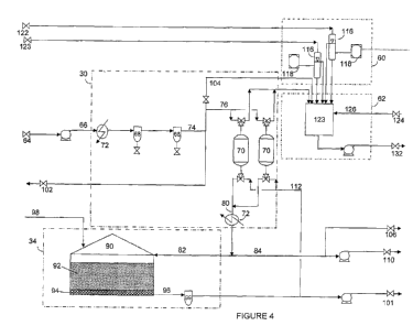
100501 Referring now to Figure 4, module 50 may include a water treatment
system 30,
a salt solution generating system 34, a sampling system 60, and a process
returns
treatment system 62. As described above, water connection 64 may be connected
to a
water supply at the drill site. The water may then be pumped via conduit 66 to
water
treatment system 30, which may include one or more filtration systems 68, and
one or
more water softening systems 70. Filtration system 68 may include bag filters,
cartridge filters, and the like. Water treatment system 30 may also include
one or
more heat exchangers 72, the location of which may depend upon whether it is
desired to heat or cool the water before, intermediate, or after filtration
and softening.
10051] The water in conduit 66 passes through the one or more filters 68 to
result in a
filtered water stream 74, a portion of which is fed via flow line 76 to water
softening
systems 70. Conditioned water (i.e., filtered and softened, and optionally
heated /
cooled) may be recovered via flow line 80. A first portion of the conditioned
water
may then be forwarded to salt solution generation system 34 via flow line 82,
and a
second portion of the conditioned water may be recovered via flow stream 84.
[0052] Salt solution generating system 34 may include one or more tanks 90
that may
be loaded with a quantity of one or more salts 92 over top of a bed of
granular
material that prevents the salt from flowing as a solid into conduit 96. As
noted
above, the salt may be loaded at the drill site or may be pre-loaded at a
remote
location, such as via an inlet 98 located on an upper portion of the tank 90.
The
conditioned water may be passed through the tank, dissolving a portion of the
salt,
and a salt solution may be recovered via flow line 96. Filter 99 may be
provided to
protect downstream equipment from any solids that may happen to pass out of
tank
90. The salt solution is then pressurized and pumped to connection 101.
100531 As illustrated, the filtered water in conduit 74 is divided into
three fractions,
fraction 76 being described above. Additionally, a portion of the filtered
water may
CA 02837194 2013-11-22
WO 2012/166670 PCT/US2012/039736
be used occasionally during routine operation of the system or for cleaning of
the
system, and may be routed to rinse water connection 102, or may be fed via
flow line
104 to purge the process returns treatment system 62. Conditioned water stream
84
may similarly serve as a softened water rinse supply, being fed to softened
water rinse
connection 106. Conditioned water stream 84 is also fed to a booster pump 108
for
feed to boost water connection 110.
[0054] Water softening system 70 may require periodic regeneration, which
may be
performed using the salt solution generated in system 34. During regeneration
of the
softening system 70, a portion of the salt solution in conduit 96 is routed
via flow line
112 to water softening system 70. The discharge is then fed via flow line 114
to
process returns system 62.
[0055] Sampling system 60 may include one or more sample valves / diverters
116,
each associated with one or more analyzers 118 for measuring residual chlorine
content, conductivity, or other properties of the treatment fluid following
contact with
the mixed oxidant solution. The samples may be transported from various points
in
the drilling or completion system, routed to module 50 via connections 120,
122.
[0056] Process returns treatment system 62 may include a storage tank 123
to
accumulate materials from various streams and vessels during operation of the
system, including process returns generated during startup of the electrolysis
unit,
sampling, water softening agent regeneration, and cleaning of the electrolytic
cells
(described below for Figure 5), among others. Process returns from cleaning of
the
electrolytic cells may be routed to module 50 via connection 124 and conduit
126, for
example.
[0057] The fluids accumulated in storage tank 123 may include water,
treatment fluid
samples, discharge from regeneration, and spent acid from electrolytic cell
cleaning.
As acid cleaning is only performed when needed, it may not be necessary to
clean the
cells at each well site or even during the disinfecting process. The process
returns
fluids generated during the operation of the mixed oxidant generation system
may
thus be fed via conduit 130 to connection 132 for fluid communication to other
well
site processes or storage tanks. For example, the process returns fluids or a
portion
thereof may be used to faun at least a portion of the treatment fluid. In this
manner,
the process returns are effectively used to form a product, and all liquid
"process
16
CA 02837194 2013-11-22
WO 2012/166670 PCT/US2012/039736
returns" generated from the system may be consumed during other well site
operations, resulting in negligible waste production as a result of the
disinfecting
process (other than solid wastes collected, such as filter cartridges, etc.).
100581 Referring now to Figure 5, module 52 may include salt solution
storage system
46, electrolytic oxidant producing unit 42, and acid wash system 136. Salt
solution
provided via connection 101 and conduit 138 and boost water provided via
connection
110 and conduit 140 are fed to the electrolytic oxidant producing unit 42. The
flow
rates and pressure of the boost water and salt solution are controlled such
that a
diluted salt solution 142 is provided to the electrolytic cells in chambers
144, 146,
producing an effluent comprising a mixed oxidant recovered via flow line 148.
The
mixed oxidant is then fed, optionally via flow line 44 to mixed oxidant
storage system
46 when storage is provided and/or desired, via flow lines 8 to connections
149 for
fluid transport of the mixed oxidant solution for contact with the treatment
fluid.
[0059] Mixed oxidant storage system 46 may include one or more vessels 150,
each
having a size of at least 500 gallons. For example, as illustrated, module 52
may
include three storage vessels 150 each holding approximately 800 gallons, for
a total
reserve volume of about 2400 gallons.
[0060] The mixed oxidant produced in electrolytic oxidant producing unit 42
is stable
for a period of about 24 hours. As such, it is not desirable to produce mixed
oxidant
solution until needed. The vessels 150, when used, may provide a buffer for
storage
of mixed oxidant solution in the event of a power failure, such as where the
power to
electrolytic oxidant producing unit 42 is inadvertently or temporarily cut
off. As it is
desired to continue feed of the mixed oxidant solution for the disinfecting
process,
even in the event of a power loss to the remainder of the system, module 52
may also
be provided with a power generator (not shown) to operate pumps 154 and the
associated control valves, so as to maintain continuity of the disinfecting
during the
fracturing operation.
[0061] A byproduct of electrolytic oxidant producing unit 42 is hydrogen,
which may
accumulate in vessels 150. To prevent excessive accumulation of hydrogen, and
to
maintain the hydrogen concentration well below flammability or explosion
limits, a
blower 160 may circulate air or nitrogen through the head space of vessels
150,
venting a hydrogen-containing vapor stream via flow line 162, which may then
be
17
CA 02837194 2013-11-22
WO 2012/166670 PCT/US2012/039736
vented to the atmosphere, fed to a flare, or otherwise disposed of safely.
Alternatively, a degassing column (not shown) may be used upstream of the
vessels
150 to separate hydrogen.
[0062] As noted above, it may be necessary to periodically clean the
electrolytic cells
due to film formation on the electrodes. Acid wash system 136 may include a
tank
containing an acid suitable to clean the electrodes, such as muriatic acid or
hydrochloric acid. The acid may then be diluted with rinse water, if
necessary, and
circulated through chambers 144, 146 to clean the electrodes. The process
returns
generated during the cleaning operation may then be routed to the process
returns tank
123, or may alternatively be managed as an individual process returns stream.
Cleaning operations and routine operation of the unit may be monitored, for
example,
using one or more analyzers 180. In some embodiments, the cleaning step may be
performed using acid generated on site using an acid generating electrolytic
cell, such
as described in U.S. Patent No. 7,922,890, for example.
100631 Cleaning water for flushing or purging components in module 52 may
be
supplied as described for Figure 4, where module 52 includes connections for
mating
with the flow line connections in module 50. These are similarly labeled in
Figure 5,
with an (a) or (b) indicating that the flow may be split to different units
following the
mating connection between the two modules.
[0064] A significant amount of particulates (sand, dust) may be present in
the air at the
drill site, especially during fracturing operations due to transport of the
proppant. To
prevent damage to electrolytic oxidant producing unit 42, the unit may be
located in
an enclosure 168 having a filtered air cooling system 170, thus providing for
circulation of filtered air through the enclosure, removing heat generated or
given off
during the electrolysis process and protecting the equipment from exposure to
conditions normally encountered at a well site during fracturing operations.
[0065] When the modular system arrives at a well site, the system may be
set up and
operational in a matter of hours (such as less than 8 hours). Connections must
be
made for fluid communication between the modules (connections 102, 106, 124,
where each may be split in the modules into one or more fractions (a), (b)),
for fluid
communication with a water supply (connection 64), for transport of the boost
water
and salt solution to the electrolytic oxidant producing unit 42 (connections
101, 110),
18
CA 02837194 2013-11-22
WO 2012/166670 PCT/US2012/039736
and for transport of the mixed oxidant solution via one or more flow lines 8
(connections 149). The remaining needs of the system are a power supply for
the
electrolytic cells, and communication conduits (hard or wireless) for
communicating
the treatment fluid flow rate, compositions, analyses, time to completion,
time to start,
and/or other information and process data to a control system 200, where the
control
system is configured to use the communicated information to control or adjust
the
flow rate of the mixed oxidant solution for contact with the treatment fluid
based on
the analyses and measured flow rates, among other possible variables. In this
manner,
the control system for the mixed oxidant systems disclosed herein may
communicate
with internal and/or external sources to control the supply of mixed oxidant
solution
to the treatment fluid.
[0066] For example, the external control system of fracturing operation may
communicate the flow rate of a fracturing fluid or one or more components of a
fracturing fluid to a well so that dosage of mixed oxidant solution added may
be
controlled to match the changes in the flow rate and/or composition through
the
cycles of a fracturing operation. As another example, the communication may
provide an indication of when to start or stop feeding of the aqueous
solution, such as
for when fracturing operations are to be concluded or to avoid mixing of the
aqueous
solution during an acid spear, commonly used at the beginning of a fracturing
operation, or when other potentially incompatible fracturing fluid additives
may be
used. As yet another example, the conamunication may provide an indication of
a
property or composition of the fluid to be disinfected, so as to properly
adjust a flow
rate of the mixed oxidant, such as when a treatment fluid additive type or
relative
amount of a treatment fluid additive is changed.
10067] As a specific control example, it may be common during a fracturing
operation
to change from an acrylamide based polymeric additive to guar. Communications
may be received by the control system indicating that the composition of the
polymeric additive is changing, and the control system may then adjust the
flow rate
of the mixed oxidant to account for an increase in oxidant demand due to the
change
in additives. Similarly, fracturing operations may switch from a non-coated
proppant
to a resin coated proppant, resulting in an increase in mixed oxidant demand.
Further,
when live breakers (e.g., non-encapsulated ammonium persulfate) are used, it
may be
19
CA 02837194 2013-11-22
WO 2012/166670 PCT/US2012/039736
desirable to decrease mixed oxidant feed rates to avoid potential reactions
that may
affect performance of breaker.
[00681 By further example, embodiments of the control process may include
one or
more of the steps of: (a) Receiving a signal indicating the flow rate of one
or more
components of a treatment fluid. The flow rate signals may be volumetric,
mass, or
weight flow rates and may provide the identity of the component_ The signal
may be
provided by the external control system of a fracturing operation, and the
signal may
be received by the control system. (b) Calculating a flow rate (also referred
to as a
dose rate) of the aqueous solution comprising oxidants from the component flow
rate
based on a predetermined oxidant demand per volumetric, mass, or weight unit
of the
component. (e) Selecting the predetermined oxidant demand for the dosing rate
calculation when the signal indicates the component corresponding to the
demand is
present in treatment fluid from a group of oxidant demands stored in the
control
system. (d) Calculating an aggregate dose rate of the aqueous solution based
on the
sum of the calculated dose rates for two or more components of the treatment
fluid.
(e) Admixing the aqueous solution to the treatment fluid at or in response to
the
calculated dose rate or aggregate dose rate. (f) Using the calculated dose
rate (or
aggregate dose rate) as the rate of admixing of the aqueous solution to the
treatment
fluid for a predetermined period of time, and then controlling, based on a
signal
indicating at least one of a residual oxidant content, a pH, a free available
halogen
content, and an oxidation reduction potential of the treated fluid. This may
be done
during the initial stages of a fracturing operation, e.g. until the operator
has
confidence that residual oxidant levels in the treatment fluid are relatively
steady. (g)
Using the calculated dose rate (or aggregate dose rate) as the rate of
admixing of the
aqueous solution to the treatment fluid until a signal indicating at least one
of a
residual oxidant content, a pH, a free available halogen content, and an
oxidation
reduction potential of the treated fluid is not changing at more than a pre-
set rate (i.e.
is steady). (h) Switching from the rate of admixing controlling based on a
signal
indicating at least one of a residual oxidant content, a pH, a free available
halogen
content, and an oxidation reduction potential of the treated fluid to using
the
calculated dose rate as set point for the rate of admixing during an ongoing
fracturing
operation when the calculated dose rate changes for a predetermined period of
time or
CA 02837194 2013-11-22
WO 2012/166670 PCT/US2012/039736
until at least one of a residual oxidant content, a pH, a free available
halogen content,
and an oxidation reduction potential of the treated fluid is steady. (i)
Increasing the
dose rate of the aqueous solution in response to the signal indicating the
composition
of the treatment fluid changing during a fracturing operation such that flow
rate of an
acrylamide-based polymeric additive decreases and the flow rate of a guar
additive
increases. (j) Decreasing the dose rate of the aqueous solution in response to
the
signal indicating the composition of the treatment fluid changing during a
fracturing
operation such that flow rate of a guar additive decreases and the flow rate
of an
acrylamide-based polymeric additive increases. (k) Increasing the dose rate of
the
aqueous solution in response to the signal indicating the composition of the
treatment
fluid changing during a fracturing operation such that flow rate of non-coated
proppant decreases and the flow rate of resin coated proppant increases. (1)
Decreasing the dose rate of the aqueous solution in response to the signal
indicating
the composition of the treatment fluid changing during a fracturing operation
such
that flow rate of resin coated proppant decreases and the flow rate of non-
coated
proppant increases. (m) Decreasing the dose rate of the aqueous solution in
response
to the signal indicating the composition of the treatment fluid during a
fracturing
operation changing such that the flow rate of a live breaker increases.
[0069] Thus, embodiments of control systems herein may be configured to
determine a
mixed oxidant demand, as well as control or adjust a flow rate of the mixed
oxidant,
based on information provided by the local or remote communications conduits.
Such
control may include feedback control, such as based on sample analyses or on-
line
measurement of residual halogen content or ORP, feedforward control, such as
based
on flow rates, compositional analyses or other information that may be
provided with
respect to the treatment fluid upstream from the mixed oxidant injection
location(s).
[0070] Control systems herein may also be configured to generate a
treatment report
that can be provided to the operator of the drilling operations. The report
may include
process operations history, presented in the form of charts, graphs, or raw
data, for
example, to summarize the performance of the disinfecting process during the
fracturing operation. For example, data may include mixed oxidant type, mixed
oxidant flow rates, measured ORP, measured pH, measured residual free
available or
total halogen concentration or other oxidant concentration, and other data
available
21
CA 02837194 2013-11-22
WO 2012/166670 PCT/US2012/039736
from the control system for monitoring and operating the disinfecting process.
In
some embodiments, the control system may be configured to integrate
disinfecting
process operations data with information received from the remote source, such
as
fracturing fluid additive types, compositions, flow rates, etc., so as to
provide an
integrated or overall operations report, inclusive of data related to the
treatment fluid
or fracturing fluid provided by the remote communications.
[0071] In other embodiments, the control system for the mixed oxidant
systems
disclosed herein may rely on the sample analyses to control the process, such
as
where external communications are not available. Containerized modules may
include such communication conduits, and control systems of containerized or
non-
containerized processes disclosed herein may be configured to operate in the
presence
or absence of such communications, thus providing flexibility to meet the
needs of the
various wellsites, regardless of their communication capabilities, that may be
treated
with mixed oxidants produced by the systems disclosed herein. Systems
disclosed
herein may also include hardware and/or software to provide for transmitting
and
receiving communications to and from the control system, such as wired or
wireless
communications from a phone, computer, or satellite, to allow remote
monitoring,
diagnostics, and/or control of system operations, for example.
[0072] As shown in Figure 5, the containerized system may include one
electrolytic
oxidant producing unit 42. While flow of fracturing or other treatment fluids
at the
well site may vary or be intermittent, it is preferred to operate the
electrolytic oxidant
producing unit 42 continuously when needed. Appropriate sizing of the
electrolytic
oxidant producing unit 42 and the buffer tanks 150 is thus important. For
example, it
may be anticipated that treatment fluid flow rates may vary from 0 barrels per
minute
to 120 barrels per minute or more during fracturing operations. Depending upon
the
water quality at the well site, at peak fracturing fluid flow rates, mixed
oxidant
solution flow rates may be on the order of 15 to 30 gallons per minute. In
such a
scenario, a mixed oxidant producing unit 42 that produces about 20 gallons per
minute, and three buffer tanks 150 each holding about 800 gallons could be
sufficient
to meet the need for disinfecting fluid at the well site throughout the
fracturing
operation, the buffer tank volume varying significantly due to the
intermittent flow of
treatment fluid. If desired, however, two or more electrolytic mixed oxidant
22
CA 02837194 2013-11-22
WO 2012/166670 PCT/US2012/039736
producing units 42 of the same or different capacity may be connected in
parallel to
provide the desired mixed oxidant supply rate. These units may be housed
within a
common enclosure 168, or in a separate enclosure 168 located on the same or
different modules.
[0073] The mixed oxidant solutions discussed herein may include
hypobromous acid
as an oxidant. In some cases, such as when disinfecting a water source
containing
ammonia, for example, hypobromous acid may be more effective than other
oxidants,
such as hypochlorous acid, possibly due to the stability of the mono halo
amines,
monochloramine being more stable than rnonobromamine. For example, fracturing
operation operations often used chemicals that generate ammonia as a by-
product,
such as glutaraldehyde, or contain ammonium salts such as ammonium persulfate,
ammonium bisulfite. Hypochlorous acid in the presence of ammonia or ammonium
salts may react to form chloramines, which are regarded as a poor disinfectant
with
less than 5% of the effectiveness of hypochlorous acid. Hypobromous acid in
the
presence of ammonia reacts to folln bromamines, which are considered to be
almost
equally effective disinfectant to hypobromous acid, and only slightly less
effective
than hypochlorous acid.
[0074] Methods for disinfecting a treatment fluid according to
embodiments disclosed
herein may include admixing a mixed oxidant aqueous solution comprising
hypobromous acid generated from a bromide salt solution with a treatment
fluid. In
one embodiment, the hypobromous acid may be generated by feeding a bromide
salt
solution to an electrolytic oxidant producing unit. Optionally, the bromide
salt
solution may be fed to the electrolytic oxidant producing unit together with
another
salt, such as a chloride salt.
[0075] Referring now to Fig. 5, a simplified flow diagram of a process
for contacting a
mixed oxidant with a treatment fluid according to embodiments disclosed herein
is
illustrated, where like numerals represent like parts. In
this embodiment,
hypobromous acid may be generated by feeding a salt solution 40, such as a
chloride
salt, to the eletrolytic oxidant producing unit 42. The oxidant solution
produced by
the electrolytic oxidant producing unit 42 may be combined with a bromide salt
solution 45 to generate hypobromous acid. For example, hypochlorous acid
produced
by electrolysis of a chloride salt solution, such as sodium chloride, may be
combined
23
CA 02837194 2013-11-22
WO 2012/166670 PCT/US2012/039736
with a bromide salt solution, such as sodium bromide or potassium bromide,
downstream from the electrolytic cell. The hypoehlorous acid oxidant reacts
with free
bromide ions in solution formed during dissolution of the bromide salt to
produce
hypobromous acid and chloride ions. For example, the mixed oxidant and bromide
salt solutions may be combined by mixing of streams 44, 45 at a mixing point
47 or
by adding the bromide salt to a reaction vessel, such as storage vessel 46,
via line 49.
The bromide salt solution may be mixed on-site by admixing the salt and water
or
transported already pre-mixed. Similar to the formation of a saturated salt
solution in
tank 34, a bromide salt may be loaded into a tank 54, on site or at a remote
site prior
to transport to the site, and contacted with water to form a bromide salt
solution.
Optionally, the premixed bromide salt solution may be further diluted with an
aqueous solution before being combined with the oxidant.
[00761 Mixed oxidants produced using chlorine salts, as noted above, may
contain
various chemical species, including hypoehlorous acid, hypochlorite, and
others.
Contact with bromide salts may be at a ratio so as to provide sufficient
bromine
content to react with some or all of the hypochlorous acid, the content of
which in the
mixed oxidant solution may depend upon numerous factors, including
electrolytic cell
type and performance, among others. Use of excess bromide salt may be
undesirable,
as bromide salts are generally more expensive than chlorine salts. In some
embodiments, a bromide salt solution and a mixed oxidant solution formed from
a
chlorine salt solution may be admixed in respective proportions to provide a
bromine
to chlorine ratio in the range from about 1:50 to about 1:1; in the range from
about
1:20 to about 1:2 in other embodiments; and in the range from about 1:5 to
about
1:15, such as about 1:10, in yet other embodiments.
[0077] As noted above, the transportable systems disclosed herein may be
delivered to
wellsites having varying degrees of communication or ability to interface with
the
control systems used in embodiments herein. As such, the control systems must
be
flexible to meet the environment encountered at the wellsite. Similarly,
transportable
systems disclosed herein may encounter wellsites having various types of
water, frac
water, chemical additives, etc., that may affect the performance of systems
disclosed
herein. Accordingly, systems as illustrated in Figure 6, including a bromide
salt
addition system may provide for flexibility between drill sites and their
varying
24
CA 02837194 2013-11-22
WO 2012/166670 PCT/US2012/039736
conditions. One wellsite may require use of bromide salts, possibly due to
ammonia,
sulfides, oxidizable iron, manganese, or other oxidant consuming species in
the frac
water / treatment fluid, and the next wellsite may not require use of bromide
salts.
Thus, embodiments disclosed herein may include use of analytical or other
techniques
to determine if use of bromide salts is necessary (e.g., measuring treatment
fluid water
quality, communicating with wellsite to determine types of chemicals added,
etc.).
[0078] Another embodiment of the method may comprise forming a treatment
fluid
from an ammonia containing water source by adding hypobromous acid to
disinfect
the water. As mentioned, other oxidants, such as hypochlorous acid, may not be
as
effective as hypobromous acid to disinfect a treatment fluid in the presence
of
ammonia. Ammonia is often found in flow-back water from fracturing operations.
By using hypobromous acid as a disinfectant, fracturing flow-back water may be
recycled for re-use during the same or in a subsequent fracturing operation.
10079] Some formations or water sources already contain bromide salts that
may be
used to generate the hypobromous acid. For example, flow-back waters from
fracturing operation in some locations in the U.S. state of Arkansas contain
bromide
salts. Thus, in some embodiments, the treatment fluid may be disinfected by
admixing an oxidant, like hypochlorous acid generated by electrolysis as
disclosed
herein, with the bromide salt-containing water to produce the hypobromous acid
with
the already existing bromide salt. Thereby, the need to transport bromide salt
to the
site of disinfection operation may be reduced or eliminated.
[0080] As described above, a system for generating a mixed oxidant useful
for
disinfecting a treatment fluid is provided. Advantageously, the system may
provide
for virtually chemical-free sterilization, using a mixed oxidant that has low
or no
toxicity, a short half life, and which degrades rapidly to naturally occurring
chemicals
following use or contact with the downhole formation. Thus, the disinfecting
process
provided by systems disclosed herein may have no or minimal environmental
impact.
The system is robust, may tolerate the harsh conditions of a well site,
including
dusting and other environmental conditions, and may use available surface
water, thus
minimizing the impact on the potable water supply at the well site.
CA 02837194 2013-11-22
WO 2012/166670 PCT/US2012/039736
[00811 In some embodiments, the system for generating a mixed oxidant may
be
containerized and transportable. Advantageously, this system may have a small
footprint, may be transported to the well site only when needed, and may be
set up
and removed from a drill site rapidly. Further, pre-loading of chemicals in
storage
tanks before transport of the system to a well site may minimize or eliminate
the need
for chemical delivery and handling at the well site.
[0082] Overall, embodiments of the processes and systems disclosed herein
may have
one or more of the following advantages:
= The treatment may be used for all fresh or recycled water (flow back,
produced, water from drilling fluids, in frac tanks, water produced during air
drilling, stagnant ponds, etc.), water and steam injection (enhanced
recovery),
packer fluids, oilfield pipelines, disposal wells, workovers, production
(replace
biocides, remove slime), and other applications in the downstream areas.
= The treatment is non-damaging to frac fluids.
= The treatment is non-damaging to the wellbore, pumps, pipelines, etc.
= The treatment is effective under all foreseeable conditions; pH,
temperature,
pressure, etc.
= The treatment will oxidize and reduce other harmful components in the
fluid:
o Organics forming food for bacteria and help prevent re-growth.
o H2S, iron and possibly some other inorganics.
= The treatment can remove slime.
= The residual may be sufficient to prevent re-growth in the wellbore and
effectively reduce the bacteria in the flow-back fluid.
= The equipment is responsive to changing water properties.
= The equipment may have single well autonomy, able to treat a frac without
re-
supply (except for diesel fuel).
= The equipment may be mobile ¨ able to go to any frac site or other
application.
= The process may have complete redundancy ¨ back-up power supply, control
system and pumps, back-up disinfectant, etc.
= The process may significantly reduce the carbon footprint and improve HSE
over existing processes.
26
CA 02837194 2013-11-22
WO 2012/166670 PCT/US2012/039736
[0083] For the sake of brevity, only certain ranges are explicitly
disclosed herein.
However, ranges from any lower limit may be combined with any upper limit to
recite
a range not explicitly recited, as well as, ranges from any lower limit may be
combined with any other lower limit to recite a range not explicitly recited,
in the
same way, ranges from any upper limit may be combined with any other upper
limit
to recite a range not explicitly recited. Additionally, within a range
includes every
point or individual value between its end points even though not explicitly
recited.
Thus, every point or individual value may serve as its own lower or upper
limit
combined with any other point or individual value or any other lower or upper
limit,
to recite a range not explicitly recited.
[0084] All priority documents are herein fully incorporated by reference
for all
jurisdictions in which such incorporation is permitted and to the extent such
disclosure is consistent with the description of the present invention.
Further, all
documents and references cited herein, including testing procedures,
publications,
patents, journal articles, etc. are herein filly incorporated by reference for
all
jurisdictions in which such incorporation is permitted and to the extent such
disclosure is consistent with the description of the present invention.
[0085] While the disclosure includes a limited number of embodiments, those
skilled
in the art, having benefit of this disclosure, will appreciate that other
embodiments
may be devised which do not depart from the scope of the present disclosure.
Accordingly, the scope should be limited only by the attached claims.
[0086] As described above, systems and processes disclosed herein may
provide for
one or more of the following embodiments, among others:
1. A process for disinfecting a treatment fluid, comprising:
admixing an aqueous solution comprising two or more oxidants generated via
electrolysis of a salt solution with a treatment fluid.
2. The process of embodiment 1, admixing one or more salts and water to form
the salt
solution.
3. The process of embodiment 1 or embodiment 2, wherein the one or more salts
comprise at least one of an alkali metal halide, an alkaline earth metal
halide, and a
transition metal halide.
27
CA 02837194 2013-11-22
WO 2012/166670 PCT/US2012/039736
4. The process of any one of embodiments 1-3, further comprising converting
the salt
solution to an aqueous solution comprising the two or more oxidants via
electrolysis.
5. The process of any one of embodiments 1-4, wherein the two or more mixed
oxidants
comprise two or more of ozone, hydrogen peroxide, hypochlorite, hypochlorous
acid,
chlorine dioxide, hypobromous acid, bromine, and chlorine.
6. The process of any one of embodiments 1-5, further comprising contacting
the
treatment fluid with the two or more oxidants for a time in the range from 1
second to
2 hours.
7. The process of any one of embodiments 1-6, further comprising measuring at
least
one of a residual oxidant content, a pH, a free available halogen content, and
an
oxidation reduction potential.
8. The process of any one of embodiments 7, further comprising adjusting at
least one of
a volumetric ratio of the aqueous solution to the treatment fluid and a
contact time
based upon the measured at least one of a residual oxidant content, a pH, a
free
available halogen content, and an oxidation reduction potential.
9. The process of any one of embodiments 2-8, further comprising treating the
water
prior to the admixing the water with the one or more salts.
10. The process of embodiment 9, wherein the treating comprises at least one
of filtering,
softening, heating, and cooling.
11. A method of servicing a wellbore, comprising:
transporting a portable tank containing a quantity of one or more salts to a
well
site to be serviced;
generating a salt solution by passing water through the portable tank to
dissolve a
portion of the salt;
converting the salt solution to an aqueous solution comprising one or more
oxidants via electrolysis;
contacting the aqueous solution with a treatment fluid to form a treated
treatment
fluid; and
placing the treated treatment fluid into the wellbore.
12. The process of embodiment 11, wherein the salt comprises at least one of
an alkali
metal halide, an alkaline earth metal halide, and a transition metal halide.
28
CA 02837194 2013-11-22
WO 2012/166670 PCT/US2012/039736
13. The process of embodiment 11 or embodiment 12, wherein the one or more
oxidants
comprise one or more of ozone, hydrogen peroxide, hypochlorite, hypochlorous
acid,
chlorine dioxide, hypobromous acid, bromine, and chlorine.
14. The process of any one of embodiments 11-13, wherein the converting step
comprises:
admixing the generated salt solution with additional water to produce a
diluted salt
solution;
electrolyzing the diluted salt solution to foul' the aqueous solution.
15. The process of embodiments 14, wherein the diluted salt solution contains
from
0.01% to 5% by weight dissolved salts_
16. The process of any one of embodiments 11-15, wherein the contacting step
comprises
contacting the treatment fluid with the two or more oxidants for a time in the
range
from 1 second to 2 hours before placing the treated treatment fluid into the
wellbore.
17. The process of any one of embodiments 11-16, further comprising measuring
at least
one of a residual oxidant content, a pH, a free available halogen content, and
an
oxidation reduction potential of the treated treatment fluid_
18. The process of any one of embodiment 17, further comprising adjusting at
least one of
a volumetric ratio of the aqueous solution to the treatment fluid and a
contact time
based upon the measured at least one of a residual oxidant content, a pH, a
free
available halogen content, and an oxidation reduction potential.
19. The process of any one of embodiments 11-18, further comprising treating
the water
prior to the use of the water in at least one of the generating step and the
converting
step.
20. The process of embodiment 19, wherein the treating comprises at least one
of
filtering, softening, heating, and cooling.
21. A portable system for disinfecting water, comprising:
(a) a fluid connection for connecting to a water supply;
(b) a treatment system for conditioning the water supplied;
(c) a tank for admixing at least a portion of the conditioned water with
one or
more salts to form a salt solution;
(d) at least one electrolytic oxidant producing unit for converting at
least a
portion of the salt solution to an aqueous solution comprising mixed oxidants;
29
CA 02837194 2013-11-22
WO 2012/166670 PCT/US2012/039736
(e) one or more tanks for storing the aqueous solution; and
(f) a fluid connection for transporting the aqueous solution from the
one or
more tanks for storing for contact with a fluid to be disinfected.
22. The system of embodiment 21, further comprising at least one of:
(g) an acid supply tank for supplying acid to periodically clean the at least
one
electrolytic oxidant producing unit;
(h) a sampling system for sampling the fluid following contact with the
aqueous
solution;
(i) a process returns tank for accumulating materials from one or more of the
treatment system, the tank for admixing, the electrolytic oxidant producing
unit(s), the one or more tanks for storing, the acid supply tank, the sampling
system; and piping, pumps, and equipment associated therewith;
(j) a fluid connection for transporting accumulated materials from the process
returns tank;
(k) one or more fluid conduits for transporting treated fluid to the sampling
system;
(1) a control system for controlling a feed rate of the aqueous solution.
23. The system of embodiment 21 or embodiment 22, wherein the treatment system
for
conditioning the water comprises at least one of:
(i) a filter for reducing a solids content of the water;
(ii) a water softening system for reducing a metals content of the water;
and
(iii)a heat exchanged for adjusting a temperature of the water.
24. The system of any one of embodiments 21-23, wherein the at least one
electrolytic
oxidant producing unit is in an enclosure having a filtered air cooling
system.
25. The system of any one of embodiments 21-24, wherein the system is modular.
26. The system of embodiment 25, comprising a first module and a second
module,
the first module containing components (a), (b), and (c);
the second module containing components (d), (e), and (t).
27. The system of embodiment 26, wherein the first module further contains at
least one
of components (h), (i), (j), and (k).
CA 02837194 2013-11-22
WO 2012/166670 PCT/US2012/039736
28. The system of embodiments 26 or 27, wherein the first module is
containerized and is
no greater in size than one twenty-foot equivalent unit (TEU) (container 20
feet long
by 8 feet wide by 9.5 feet tall) (6.1 m x 2.4 m x 2.9 m) (1520 cu ft or 43
m3).
29. The system of any one of embodiments 26-28, wherein the second module
further
contains at least one of components (g) and (I).
30. The system of any one of embodiments 26-29, wherein the second module is
containerized and is no greater in size than one forty-foot equivalent unit
(FEU)
(container 40 feet long by 8 feet wide by 9.5 feet tall) (12.2 m x 2.4 m x 2.9
m) (3040
cu ft or 87 m3).
31. The modular system of embodiment 30, wherein the one or more tanks for
storing the
aqueous solution (e) comprises at least two tanks each having a volume of at
least 500
gallons.
32. The system of any one of embodiments 22-31, further comprising one or more
communication conduits for sending or receiving a signal with the control
system
from a local or remote source, where the signal may be used to monitor or
control the
system and/or may provide an indication of at least one of:
an indication of when to start or stop feeding the aqueous solution, such as
to
avoid mixing of the aqueous solution during an acid spear, commonly used at
the beginning of a fracturing operation;
at least one of a residual oxidant content, a pH, a free available halogen
content,
and an oxidation reduction potential of the treated fluid;
a flow rate of at least one of the fluid to be disinfected, a treatment fluid
precursor,
and the treated fluid; and
a property of at least one of the fluid to be disinfected, a treatment fluid
precursor,
and the treated fluid after contact of the aqueous solution with the fluid to
be
disinfected, for example, a composition of the treatment fluid, such as a
treatment fluid additive amount or type.
33. The system of embodiment 32, wherein the control system is configured to
control the
feed rate of the aqueous solution both in the presence of and absence of
receiving the
signal with the control system from the remote source.
34. A method of disinfecting a fluid, comprising:
disposing a quantity of one or more salts in a tank;
31
CA 02837194 2013-11-22
WO 2012/166670 PCT/US2012/039736
receiving water from a water supply;
treating the water received in a water treatment system to form a conditioned
water stream;
generating a salt solution by passing a first portion of the conditioned water
through the tank to dissolve a portion of the one or more salts;
combining the salt solution with a second portion of the conditioned water to
form
a diluted salt solution;
feeding the diluted salt solution to one or more electrolytic oxidant
producing
units to convert the salt solution to an aqueous solution comprising one or
more oxidants via electrolysis;
contacting the aqueous solution with a fluid to form a treated fluid.
35. The process of embodiment 34, further comprising sampling the treated
fluid using a
sampling system and measuring at least one of a residual oxidant content, a
pH, a free
available halogen content, and an oxidation reduction potential of the treated
fluid.
36. The process of embodiment 34 or embodiment 35, wherein the treating
comprises at
least one of filtering, softening, heating, and cooling.
37. The process of any one of embodiments 34-36, further comprising cleaning
or
purging at least one of the tank, the electrolytic oxidant producing unit(s),
the
sampling system, and the water treatment system using at least one of the
water
received, a third portion of the conditioned water, the salt solution, and an
acid.
38. The process of embodiment 37, further comprising accumulating a process
returns
stream from the cleaning or purging.
39. The process of embodiment 38, wherein the fluid is a treatment fluid, the
process
further comprising using at least a portion of the process returns stream to
form at
least a portion of the treatment fluid.
40. The process of embodiment 39, further comprising placing the treated
treatment fluid
into a wellbore.
41. The process of any one of embodiments 34-40, further comprising
transporting the
tank containing the disposed quantity of one or more salts to a well site to
be serviced.
42. A method of fracturing a subterranean formation comprising:
disposing a quantity of one or more salts in a tank;
receiving water from a water supply;
32
CA 02837194 2013-11-22
WO 2012/166670 PCT/US2012/039736
treating the water received in a water treatment system to form a conditioned
water stream;
generating a salt solution by passing a first portion of the conditioned water
through the tank to dissolve a portion of the one or more salts;
combining the salt solution with a second portion of the conditioned water to
form
a diluted salt solution;
feeding the diluted salt solution to one or more electrolytic oxidant
producing
units to convert the salt solution to an aqueous solution comprising one or
more oxidants via electrolysis;
contacting the aqueous solution with a fluid to form a treated fluid; and
using at least a portion of the treated fluid in a fracturing operation.
43. The process of embodiment 42, further comprising transporting the tank
containing
the disposed quantity of one or more salts to a well site to be serviced.
44. A method of servicing a wellbore, comprising:
contacting a treatment fluid or treatment fluid precursor with an aqueous
solution
comprising one or more oxidants produced via electrolysis of a salt solution
to
form a treated fluid;
placing the treated fluid in the wellbore.
45. The method of embodiment 44, wherein the treatment fluid is a fracturing
fluid used
in a fracturing operation.
46. The method of embodiment 44 or embodiment 45, further comprising measuring
at
least one of a residual oxidant content, a pH, a free available halogen
content, and an
oxidation reduction potential of the treated fluid.
47. The method of embodiment 46, further comprising adjusting a rate of the
aqueous
solution provided for the contacting based upon at least one of:
the measured at least one of a residual oxidant content, a pH, a free
available
halogen content, and an oxidation reduction potential of the treated fluid;
a flow rate of at least one of the treatment fluid, the treatment fluid
precursor, and
the treated fluid; and
a measured property of the treatment fluid or treatment fluid precursor fed to
the
contacting.
33
CA 02837194 2013-11-22
WO 2012/166670 PCT/US2012/039736
48. The method of any one of embodiments 44-47, further comprising foiming a
salt
solution and converting the salt solution via electrolysis to form the aqueous
solution.
49. The method of embodiment 48, further comprising storing a quantity of one
or more
of the salt solution and the aqueous solution in a storage vessel.
50. The method of embodiment 49, further comprising controlling one or more of
the
electrolysis, the forming a salt solution, the converting the salt solution,
the storing,
the adjusting, and the measuring using a control system.
51. The method of embodiment 50, further comprising receiving a signal with
the control
system from a local or remote source, where the signal provides an indication
of at
least one of:
the measured at least one of a residual oxidant content, a pH, a free
available
halogen content, and an oxidation reduction potentialof the treated fluid;
a flow rate of at least one of the treatment fluid, the treatment fluid
precursor, and
the treated fluid; and
a measured property of the treatment fluid or treatment fluid precursor fed to
the
contacting.
52. The method of embodiment 51, wherein the control system is configured to
control
the one or more of the electrolysis, the forming a salt solution, the
converting the salt
solution, the storing, the adjusting, and the measuring both in the presence
of and
absence of receiving the signal with the control system from the remote
source.
53. A method for disinfecting a treatment fluid, comprising:
admixing an aqueous solution comprising hypobromous acid generated from a
bromide salt solution with a treatment fluid.
54. The method of embodiment 53, wherein the hypobormous acid is generated by
a
method comprising: feed the bromide salt solution to an electrolytic cell.
55. The method of embodiment 53, wherein the hypobromous acid is generated by
a
method comprising:
feeding a chloride salt solution to an electrolytic cell to form an oxidant
solution
comprising hypochlorous acid; and
34
CA 02837194 2013-11-22
WO 2012/166670 PCT/US2012/039736
admixing the oxidant solution to the bromide salt solution.
56. The method of embodiment 53, where the hypobromous acid is generated by a
method comprising:
feeding the bromide salt solution and a chloride salt solution to an
electrolytic cell.
57. The method of any one of embodiments 53-56, comprising admixing at least
one
bromide salt and water to form the bromide salt solution.
58. A method for fanning a treatment fluid using an ammonia-containing water
source,
the method comprising:
admixing an aqueous solution comprising hypobromous acid generated from a
bromide salt solution to the ammonia-containing water.
59. A method for recycling flow-back water from a fracturing operation
comprising:
admixing an aqueous solution comprising hypobromous acid generated from a
bromide salt solution with the flow-back water; and
re-using the flow-back water in a fracturing operation.
60. A method recycling flow-back water from a fracturing operation comprising:
storing the flow-back water containing ammonia and a bromide salt in a tank or
pond;
admixing the flow-back water with an oxidant solution generated by on-site
electrolysis of a chloride salt solution; and
re-using the flow back water in a fracturing operation.
[0087] Although only a few example embodiments have been described in
detail
above, those skilled in the art will readily appreciate that many
modifications are
possible in the example embodiments without materially departing from this
invention. Accordingly, all such modifications are intended to be included
within the
scope of this disclosure as defined in the following claims. In the claims,
means-plus-
function clauses are intended to cover the structures described herein as
perfoiming
the recited function and not only structural equivalents, but also equivalent
structures.
Thus, although a nail and a screw may not be structural equivalents in that a
nail
employs a cylindrical surface to secure wooden parts together, whereas a screw
CA 02837194 2013-11-22
WO 2012/166670 PCT/US2012/039736
employs a helical surface, in the environment of fastening wooden parts, a
nail and a
screw may be equivalent structures. It is the express intention of the
applicant not to
invoke 35 U.S.C. 112, paragraph 6 for any limitations of any of the claims
herein,
except for those in which the claim expressly uses the words 'means for'
together
with an associated function.
36