Note: Descriptions are shown in the official language in which they were submitted.
MULTILAYER FLUID HEAT EXCHANGER CONTAINER
The present invention relates to a system and a method for the delivery of
heated or
cooled therapeutic fluids.
Systems designed to heat or cool and deliver therapeutic fluids are widely
known and
described in the art. These systems generally combine an electronic warming
unit containing
heating plates or electronic cooling device or a bath of warmed or cooled
fluid, and a
disposable heat exchanger container. The use of containers configured as
"cassettes" to act as
heat exchangers has also been described. The containers are commonly made by
at least two layers
of plastic material which are welded to each other using methods such as
thermal or high
frequency welding to define a fluid path between the two layers.
Plastic is often a preferred material because it is relatively inexpensive, it
is easy to
mould and manipulate. However, the majority of known plastic materials do not
conduct heat
efficiently. On one hand, in view of the poor conductivity of plastic
materials, it is preferable
for the plastic sheets forming the container to be as thin as possible. On the
other hand the
plastic sheets should be thick enough to warranty the homogeneity during the
manufacturing
process and safety (for example the absence of leaks) during the intended end
use. In addition,
the limitations on the thickness of the plastic layers affects the rigidity of
the resulting container,
which often require to be reinforced with an external rigid frame to enable
positioning and
insertion into the warming unit.
An alternative to plastic container is metallic containers which normally
offer better
performance than plastic containers in terms of thermal conductivity, but they
are more
expensive, more difficult to manipulate and less biocompatible. Metallic
containers are more
rigid and do no usually need reinforcing frames, but this rigidity creates
manufacturing
complications, in particular because the surface of the container contacting
the heating plate
of the warming device must be flat to ensure a good fit and with sufficient
contact surface to provide
effective heat transfer between the two elements.
It is an object of this invention to mitigate problems such as those described
above.
CA 2837430 2019-04-02
CA 02837430 2013-11-26
WO 2012/168451 PCT/EP2012/060930
2
The invention will be further described with reference to the drawings and
figures, in
which:
figure 1 is a schematic representation of a first fluid warming or cooling
container
according to the present invention;
figure 2 is a schematic representation of a first multilayer structure for a
fluid warming
or cooling cassette according to the present invention;
figure 3 is a schematic representation of a second multilayer structure for a
fluid
warming or cooling cassette according to the present invention;
figure 4 is a schematic representation of a first fluid connector for a fluid
warming or
cooling cassette according to the present invention; and
figure 5 is a schematic representation of a second fluid connector for a fluid
warming or
cooling cassette according to the present invention;
figure 6 is a schematic representation of the different layers of a second
fluid container
according to the present invention;
figures 7A and 7B are schematic representations of a third fluid connector for
a fluid
warming or cooling cassette according to the present invention;
figures 8A to 8C are schematic representations of a third fluid warming or
cooling
container according to the present invention;
figure 9 is a schematic representation of a fourth fluid container according
to the present
invention;
figure 10 is a schematic representation of a fifth fluid container according
to the present
invention;
figure 11 is a schematic representation of a sixth fluid container according
to the present
invention;
figure 12 is a schematic representation of a seventh fluid container according
to the
present invention;
figure 13A is a schematic representation of a cross section of a fluid channel
of a plastic
fluid warming or cooling container;
figure 13B is a schematic representation of a cross section of a fluid channel
of fluid
warming or cooling container according to the invention.
3
The heat exchanger container according to the present invention comprises a
combination of plastic and metallic layers and is used in combination with an
electronic
warming device or an electronic cooling device or a bath of warmed or cooled
fluid. The
container may be used in combination with a fluid warming unit comprising
heating plates or
with a cooling unit comprising cooling plates. Cooling systems are for example
particularly
useful in neurological protection after a cardiac arrest or during cardiac
surgery to cool down
patient's blood for a period of time before warming it up to normal
temperature under
accurate control.
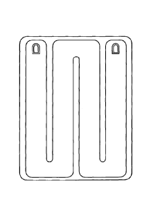
Referring to figure 1, there is illustrated a fluid warming or cooling
container 1
comprising a fluid inlet port 2 and a fluid outlet port 3. The fluid inlet
port 2 is, in use, in fluid
communication with a fluid reservoir, typically a therapeutic fluid bag (not
shown). The fluid
outlet port 3 is, in use, in connection with a patient. Biocompatible plastic
tubing means, such
as PVC or silicone or polyurethane tubes, may be used to connect the ports 2,3
to the fluid
reservoir or to the patient.
With reference to figures 2 and 3, the container comprises a first layer 4
comprising
metal foil and a second internal layer 5 comprising a biocompatible plastic
material.
The metal foil preferably comprises a highly conductive semi-rigid material
such as an
aluminium foil. More preferably, the metal foil comprises an aluminium foil
(such as an
aluminium soft foil) with a minimum 98% purity. Aluminium is the preferred
material
because it is readily available and therefore cheap. In addition, it is widely
produced as a foil,
which is a malleable form with good plasticity. Other highly conductive
materials have been
considered but copper was found to be less biocompatible, toxic and more
expensive than
aluminium; steel did not have as good a plasticity and conductivity; gold was
more expensive.
Preferably, the thickness of the first layer 4 is less than 60 microns. A
first layer 4 with a
thickness of more than 60 microns would not have the required flexibility and
heat transfer
properties. The first layer 4 should also be thin enough to allow it to
slightly expand so that
good contact can be made with the heating plate. If too thick, the layer
becomes too rigid and
the heating plate or heat exchanger must be moved or manipulated to create
enough pressure
to ensure an efficient transfer of heat. The first layer 4 provides for a more
effective heat
CA 2837430 2018-11-07
CA 02837430 2013-11-26
WO 2012/168451 PCT/EP2012/060930
4
transmission from the heating plates of the fluid warming unit to the
therapeutic fluid (or
from the therapeutic fluid to the cooling plates of the fluid cooling device)
due to the presence
of metallic foil. Moreover, the energy delivered to the system during the
welding process of
the manufacturing of the container 1 is transferred effectively and
homogeneously.
Preferably, the thickness of the first layer 4 is more than 30 microns. This
is because,
below this range, the metal foil would not have the required rigidity to be
inserted into the
opening of the warming or cooling unit. The first layer 4 comprising metal
foil is
advantageous in that it provides the correct rigidity and consistency to the
container 1. This
semi-rigidity of the container 1 of the present invention, on one hand, makes
the manufacture
and manipulation of the container 1 easier, and, on the other hand, enables
the user to insert
the container 1 into a fluid warming or cooling unit. The container 1 may be
used without the
need of any supporting frame or structure to facilitate the insertion of the
container 1 into a
fluid warming or cooling unit.
It should also be noted, with respect to the preferred manufacture process,
that if the
first layer 4 is too thick then it becomes difficult to vacuum form the multi
layer; if the first
layer 4 is too thin, then the integrality of the layer becomes compromised
when the structure
is stretched.
More preferably, the thickness of the first layer 4 is 45 microns 8%.
Ideally, the metal
foil layer 4 has a thickness of approximately 45 microns and a density of
approximately
121.50 glin2 for the optimum heat transfer versus rigidity balance.
The material chosen for layer 5, should be a high biocompatible material,
homogeneous,
easy to manipulate, inexpensive and compatible with the adhesive substances
used during the
laminating process (join to the metallic layer 4) and suitable for thermal or
radiofrequency
welding (container production process). An example of this material is PVC
(preferably free
of DHP).
Preferably, the thickness of the second layer 5 ranges from 45 microns to 75
microns.
This is because when the internal layer 5 is thinner than 45 microns, it
becomes difficult to
process and to manipulate and does not provide a surface thick enough for
efficient bonding
or welding to the other layer(s). In addition, when the second layer is too
thin, then the weld
CA 02837430 2013-11-26
WO 2012/168451 PCT/EP2012/060930
will be too weak to withstand the pressure of fluid during use and can
potentially burst.
When the internal layer 5 is thicker than 75 microns, the heat transfer, and
consequently the
performance of the system, could be reduced. The most preferred thickness for
the internal
layer 5 is approximately 60 microns + 10%.
5
The internal layer 5 is the biocompatible plastic layer which, in use, comes
in contact
with the therapeutic fluid (e.g. fluid or blood) and therefore preferably
comprises a medical
grade plastic. In addition, it is preferred that this internal layer 5
comprises a thermo-sealable
material to act as a welding material between the two metal foil layers 4 of
the container 1.
The first and second layers 4, 5 are joined together or laminated together in
order to act
as a single structure which contains on one surface the biocompatibility of
the internal layer 5
and the physical properties (i.e. thermo conductivity and semi-rigidity) of
the metal foil layer
4. Preferably, the layers 4, 5 are joined together using adhesive means. More
preferably, the
adhesive means comprises a polymeric adhesive such as a polyester/polyurethane
adhesive.
Optionally, the container 1 comprises a third external layer 6, preferably a
layer
comprising a plastic material. In a preferred embodiment, first layer 4
comprising a metal foil
is located between the second layer 5 comprising a biocompatible plastic
material and the
external layer 6, thereby forming a three layer structure. The addition of
this third external
layer 6 presents a number of advantages, such as:
1. In the two-layer structure, the first layer 4 comprising a metal foil is
exposed. There
is therefore a risk of contamination of the heat exchanger by small metal
particles being
shaved or dislodged during the manufacturing process and falling inside the
fluid channel. By
adding the third external layer 6, the first layer 4 is sandwiched between two
layers of plastic
materials and such contamination can be prevented.
2. As strong thermal weld is obtained when the sheet comprises a third
external layer 6,
so that it can withstand fluid being passed through the channel with the risk
of being
breached.
CA 02837430 2013-11-26
WO 2012/168451 PCT/EP2012/060930
6
Preferably, the external layer 6 comprises a film comprising a material,
preferably a polymer material such as polyamide or an oriented polyamide film.
Oriented
polyamide is most preferred because it offers improvements such as allowing
easy printing on
its surface. In addition, this external layer 6 may be added to avoid the
liberation of
potentially toxic metal particles during the manufacturing process.
Preferably, the thickness of the third external layer 6 is preferably less
than 35 microns.
This layer must be thick enough to provide some integrality and to print onto,
but at the same
time as thin as possible to ensure good conductivity as it is a natural
insulator. More
preferably the thickness ranges from 15 microns to 35 microns. The most
preferred thickness
for the third layer 6 is approximately 25 microns + 10%.
This third as well any potential additional layer incorporated to the system
should join
the first and second layers 4, 5 and act as a single structure as described
previously. This
external layer 6 is designed to be in contact with the heating plate of the
electronic warming
or the cooling plates of a cooling unit. It preferably has high
biocompatibility and enables
relatively easy and clean manipulation during the manufacturing process. It
transfers
effectively and homogeneously the heat and energy delivered to the system
during the
welding process of the manufacturing of the heat exchanger.
Preferably, the thickness of the triple layer structure ranges from 90 microns
to 170
microns. The most preferred thickness for the triple layer structure including
the adhesive is
approximately 138 microns 10%.
Coming back to figure 1, the first and second layer 4, 5 and optionally third
layer 6 or
other optional layers, are joined together to form a sheet 7. The container is
preferably made
of two sheets 7 which are joined together to form a fluid channel 8 to enable
the passage of a
fluid from the inlet port 2 to the outlet port 3. Preferably, the fluid
channel 8 defines a
serpentine path.
The fluid channel is obtained preferably by application of vacuum, or
mechanical press
using pressure to specific areas of the multilayer sheets so as to define its
shape, such as the
CA 02837430 2013-11-26
WO 2012/168451 PCT/EP2012/060930
7
preferred serpentine shape. Because the unique nature of the material it is
able to hold
the shape when vacuumed or stamped the fluid path is better defined and holds
its shape
during use. Thus, the fluid can flow through the channel substantially
unimpeded, and the
homogeneous contact surface between the heat exchanger and the heating/cooling
plate is
warranted.
The fluid container 1 may be a generally flat rectangular container. The inlet
port 2 and
outlet port 3 are preferably located adjacent the edge of the container 1. The
port 2, 3 may
comprise a first portion 2a extending substantially perpendicularly from the
surface of the
container 1. Tubing 10 may be connected directly to the end of the first
portion 2a (see figure
4). Alternatively, port 2, 3 may comprise a second portion 2b extending
substantially
perpendicularly from the end of the first portion 2a (or substantially
parallel to the surface of
the container 1) and tubing 10 may be connected to the end of the second
portion 2b (see
figure 5). The port 2,3 or connector shown in figure 5 is preferred because
the port-tubing
formation is more compact and occupies less space than that shown in figure 4.
The most
preferred connectors 2, 3 are shown in figure 7A and 7B, which are constructed
and arranged
so that the tubing extends along the surface of the container, as opposed to
perpendicularly to
the surface of the container.
With reference for example to figures 8A to 8C, the fluid warming or cooling
container
of the present invention may comprise a fluid channel 8 defining a serpentine
path. Because
of its physical properties, the multilayer film which includes metal foil can
easily be shaped in
any required form. Technologies involving for example, vacuum forming, thermal
forming or
positive pressure apparatus may be used. The serpentine form is preferred as
it increases the
surface area and therefore improves the conductivity.
Another feature increasing the surface area and therefore the conductivity is
the
substantially flat surface of the fluid warming or cooling container
contacting the heating
plate of the warming device (or the cooling plate of the cooling device). As
can be seen in
figure 13A, known plastic fluid warming containers have a generally circular,
or curved, cross
section. Because of the flexibility of the plastic materials used to prepare
those containers, the
fluid channel will have a tendency to form a circular or curved, shape as it
is filled with fluid.
CA 02837430 2013-11-26
WO 2012/168451 PCT/EP2012/060930
8
Thus the area of the fluid channel actually contacting the heating plate of
the warming
device is significantly reduced.
By contrast, the fluid warming container of the present invention may comprise
fluid
channel 8 with at least one substantially flat surface for contacting the
heating plate of the
warming device or the cooling plate of the cooling device (see figure 13B).
The container
comprises a metal layer which provides the required malleability but also
rigidity to produce
such a surface. It is possible to achieve a similar shape and rigidity using
different material
combinations however in order to do so it is likely the container would have
to increase in
thickness, in doing so would compromised the design and effect heat transfer.
Preferably, the fluid channel 8 has a rounded serpentine shape, i.e. without
any angles t
facilitate the flow of fluids (see for example the containers of figures 8-
12).
In use, the therapeutic fluid is contained in, for example, a fluid bag hooked
onto a fluid
bag holder. The fluid bag is in fluid communication with the inlet port 2 of
the container 1, for
example via a plastic tube 10. The outlet port 3 of the container 1 is in
fluid communication
with the patient for example via a second plastic tube 10. The container 1 is
inserted into a
fluid warming device, which comprises heating means, preferably two heating
plates. The
fluid is circulated using pump means or gravity from the fluid bag to the
inlet port 2 of the
container 1. The fluid flows through the serpentine fluid channel 8 and is
heated to a suitable
temperature by heat transfer from the heating plates through the sheets 7 of
the container 1.
The temperature of the fluid may be adjusted using temperature control means,
for example,
as those described in the Applicant's own British patent application GB
1021898Ø The
heated fluid exits the container 1 via outlet port 3 and is delivered to the
patient via tubing 10.
Alternatively, the container 1 is inserted into a fluid cooling device, which
comprises
cooling means, which could be two cooling plates or a bath of cooled or warmed
fluid. The
fluid flows through the serpentine fluid channel 8 and is cooled to a suitable
temperature by
heat transfer from therapeutic fluid to the cooling means through the sheets 7
of the container
1. The cooled fluid exits the container 1 via outlet port 3 and is delivered
to the patient via
tubing 10.
CA 02837430 2013-11-26
WO 2012/168451 PCT/EP2012/060930
9
The present invention provides a high performance fluid warming system, with a
container with improved heat transfer properties, mostly due to the reduced
thickness of the
plastic material (which is a poorly conductive material), to the superior heat
transfer
properties of the metal foil layer, and to the correct rigidity to provide
homogeneous and
effective contact surface between the heating plates of the fluid warming unit
(or the cooling
plates of the fluid cooling unit) and the fluid container in the heat
exchanger.
The container of the present invention is advantageous in that the multilayer
structure is
able to slightly expand during use so that it meets the heating plates and
ensure an improved
transfer of heat and good warming performance. Another advantage arising from
this ability
to control the expansion is that it is possible to remove the heat exchanger
container from in
between the two heating plates without having to empty the container of fluid,
i.e. to "de-
prime" the container. The container expands enough to ensure good contact with
the heating
.. plates and not too much so that it cannot be removed from the warming
device. The container
can therefore be taken out of the warming system after the procedure without
having to
disconnect the fluid bag in the operating room and then to re-insert the fluid
bag into another
recovery system in the recovery room. By contrast, when a heat exchanger is
made of a
material mix that allows for expansion, the container is under pressure when
filled with fluid
.. and cannot be removed from the warming device without de-priming.
The production process is simplified and therefore manufacturing costs are
reduced for
example because easy and homogeneous welding of the multilayer foil is
possible.
Furthermore, no additional structure (e.g. frames) is required to support the
container to
facilitate the insertion into the heat warming or cooling unit. In addition,
the materials used to
manufacture the container of the present invention are relatively inexpensive
materials.
Example
An example of a multilayer structure for a container according to the
invention is provided:
CA 02837430 2013-11-26
WO 2012/168451 PCT/EP2012/060930
later T-ii::=(.!- ess, To erar.::e
onert.9,:j pokiarr-,1?:! =
._.Cl:F i IDurity !;i8c=.:: min. ______________________ 1.5I:
polyszei--::;c:)1.yuretiare
2?7.51=
A three-layer sheet structure with preferred thicknesses (microns) is shown in
figure 6.
5 The structure once it has completed at least one sterilization process
according to
medically required standards has a shelf life of up to five years when
properly stored. In terms
of storage, the presence of the biocompatible material in the structure of the
present invention
ensures that there is no leakage from the metal foil layer when therapeutic
fluid is passed
through the container. The presence of the external layer provides additional
protection of the
10 content of the container.