Note: Descriptions are shown in the official language in which they were submitted.
CA 02837636 2015-07-31
Pumping device for a fluid container
The present disclosure relates generally to pumping devices, and more
particularly
to a pumping device for dispensing a fluid from a container.
BACKGROUND OF THE INVENTION
Pumping devices for fluid containers are in general provided with an actuator
and
a head part connected to the fluid container. Between the actuator and the
head
part a coil spring is provided in order to repel the actuator from the head
part. As
the actuator is pushed downwards, an outlet valve in the actuator is opened
and
fluid is dispensed through an orifice or a spray nozzle. When the actuator is
released it will return to its starting position and simultaneously an inlet
valve at the
head part will be opened and fluid in the container will be sucked into the
pump
chamber between the actuator and the head part.
These known pumping devices have many different parts with a complicated
structure and therefore they are tedious to manufacture. Further the coil
spring is
normally made of spring steel which has to be protected from the liquid in the
container. Another drawback is that the different parts of the pump devices
have to
be assembled manually.
US 6,227,414B1 describes for instance a dispensing device for liquid with a
sup-
port in an opening of a receptacle which encloses the product to be dispensed.
The support has a central tubular conduit, a pushbutton axially slidably
mounted
on the support between a rest position and an active position and a product
outlet
conduit. An intermediate piece of a resiliently deformable material is
provided
between the support and the pushbutton. The intermediate piece and the push-
button define a measured quantity chamber for the product. The intermediate
piece has an opening for communication between the tubular conduit of the sup-
port and the measured quantity chamber, and sealingly bears against at least
one
CA 02837636 2015-07-31
2
opening for passage between the measured quantity chamber and the outlet con-
duit of the pushbutton.
A drawback of this known dispensing device is that the outlet conduit is
ending in
the upper cap of the pushbutton and therefore not very practicable. In
addition
since there are two parallel walls in the intermediate piece which have to be
stretched if the pushbutton is actuated the resilient resistance is quite
high.
Another drawback is that the dispensing device might drip after dispensing the
product.
In DE 10 2008 029 004 Al a dispenser is described for dispensing fluid or
pasty
products with a supply chamber, a head piece, a pump chamber, an inlet valve
and an outlet valve, wherein the pump chamber is made as an integral body from
a resilient plastic material. The pump chamber body comprises a bottom connec-
t 5 tion part which is formed as a ring collar. The outlet valve exists of
a separate flat
piece which is cooperating with the pump chamber body. If the head piece is
actuated the pump chamber body is pressed down so that it is bulged. Therefore
the volume of the pump chamber is only marginally reduced by the pump chamber
body and the pump action is less efficient as with a piston cylinder
embodiment.
OBJECT OF THE INVENTION
It is the object of the present invention to provide a pumping device with
less parts
which have a more simple form and can be manufactured and assembled more
easily and preferable in an automatic assembling process.
This object may be achieved by providing a pumping device in accordance with
the present disclosure.
The pumping device of the present invention has the large advantage that
merely
less different parts are necessary, whereas the pumping mechanism is very
relia-
3
ble. Also the irksome dripping of know pumping devices is prevented by the
suck-
back chamber of the present pumping device.
SUMMARY OF THE INVENTION
In accordance with one aspect of the present invention that the spring
function is
provided by the membrane part and simultaneously the inlet and outlet valves
are
integrated by the membrane part.
In accordance with another aspect of the invention, there is provided a
pumping
device for dispensing a fluid from a container comprising: (a) a fluid
chamber; and
(b) a piston for reducing the volume of the fluid chamber, comprising an
actuator
and a head part which is connectable onto the container, wherein the actuator
comprises an outlet conduit and a first cylindrical member, and the head part
comprises a second cylindrical member which is arranged coaxially to the first
cylindrical member, further comprising a folded membrane member provided
between the first and second cylindrical members, wherein the folded membrane
member has an inlet valve and an outlet valve, such that the first and second
cylindrical members and the folded membrane member provide a variable
pumping chamber, wherein the inlet valve is sealed on a central upwardly
directed
protrusion of the head part and the outlet valve is slideably arranged
relative to
the actuator or slideably arranged relative to the head part, such that the
outlet
valve and a contact location of the outlet valve with the actuator are moved
along
the actuator synchronously with the pumping movement of the actuator back and
forth towards the head part or the outlet valve and a contact location of the
outlet
valve with the head part are moved along the head part synchronously with the
pumping movement of the actuator back and forth towards the head part, and in
such a manner that a suck-back chamber with a variable volume is provided
between the outlet valve and the outlet conduit, which variable volume is
synchronously reduced and increased as the volume of the pumping chamber is
reduced and increased by said pumping movement.
In another aspect, the present invention provides a pumping device for
dispensing
a fluid from a container having a fluid chamber and a piston for reducing a
volume
of the fluid chamber during operation, the pumping device comprising: an
actuator
CA 2837636 2018-02-27
3a
including an outlet conduit and a first cylindrical member; a head part which
is
connectable onto the container, the head part including a second cylindrical
member which is arranged coaxially to the first cylindrical member of the
actuator;
and a membrane member provided between the first cylindrical member of the
actuator and the second cylindrical member of the head part, the membrane
member providing an inlet valve and an outlet valve, wherein the first
cylindrical
member of the actuator, the second cylindrical member of the head part and the
membrane member define a variable pumping chamber, and wherein the inlet
valve is sealed on a central upwardly directed protrusion of the head part and
the
outlet valve is slideably arranged relative to the actuator or slideably
arranged
relative to the head part, such that the outlet valve and a contact location
of the
outlet valve with the actuator are moved along the actuator synchronously with
the pumping movement of the actuator back and forth towards the head part or
the outlet valve and a contact location of the outlet valve with the head part
are
moved along the head part synchronously with the pumping movement of the
actuator back and forth towards the head part, and in such a manner that a
suck-
back chamber with a variable volume is provided between the outlet valve and
the outlet conduit, which variable volume is synchronously reduced and
increased
as the volume of the pumping chamber is reduced and increased by said pumping
movement.
DESCRIPTION OF AN EMBODIMENT OF THE INVENTION
The invention will now be described in greater detail, by way of example, with
reference to the accompanying drawings, in which:
Fig. 1 shows a pumping device connected to a container in the released
position,
CA 2837636 2018-02-27
CA 02837636 2015-07-31
4
Fig. 2 shows different positions of the pumping device,
Fig. 3 shows an alternative design of the pumping device, and
Fig. 4 shows an alternative design of the membrane member.
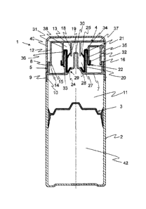
In Fig. 1 a pumping device 1 is depicted which is screwed on top of a
container 2
which has a piston 3 for expelling fluid out of the container 2. The pumping
device
1 has an actuator 4 and a head part 5. The head part 5 has a bottom 7 with an
outer ring cylinder 8 on top and bottom ring cylinder 9 with an inner screw
thread
10 for connecting the head part 5 to the container 2. Between the head part 5
and
the piston 3 a fluid chamber 11 is formed in the container 2. The actuator 4
has an
outer cylindrical cover 12 with a flat top 13 and is provided at its open end
14 with
a ring-shaped outer bulge 15, which cooperates with an inner bulge 16 at the
outer
ring cylinder 8 of the head part 5, so that the actuator 4 is slideably
received in the
head part 5. The actuator 4 has further at the inside a first cylindrical
member 18
with a lower open end 19. A second cylindrical member 20 with an upper open
end
21 is mounted on top of the head part 5. The diameter of the first cylindrical
member 18 is smaller than the diameter of the second cylindrical member 20,
i.e.
the first cylindrical member 18 is circumvented by the second cylindrical
member
20. Between the first cylindrical member 18 and the second cylindrical member
20
a membrane member 22 with a lower inlet valve 24 and an upper outlet valve 25
is
provided, such that a pump chamber 27 is formed. Centrally on the head part 5
a
small cone 28 is provided with an opening 29 towards the container 2. The
inlet
valve 24 provided by a conical lip of the membrane member 22 is resting on the
cone 28 and thus closing the opening 29. The outlet valve 25 provided also by
a
conical lip is resting towards the outer wall of the first cylindrical member
18, so
that the outlet valve 25 is also closed. On the small cone 28 a closed tube 30
can
be provided for reducing the volume of the pump chamber 27. However, this
closed tube 30 is not necessary for the function of the present pumping device
1.
CA 02837636 2015-07-31
For instance in the embodiment of Figures 2a to 2e (see below) there is no
closed
tube 30, but only the small cone 28 with one or more openings 29.
The actuator 4 has further a third cylindrical member 31 with a lower ring-
shaped
5 open end 32 which has a slightly larger diameter than the second
cylindrical mem-
ber 20 and thus providing a clearance 33 between the cylindrical members 20
and
31. The membrane member 22 is folded at the upper edge 34 and has a resilient
part 35 which is sealing the clearance 33 and is ending in a lock seam 36,
which is
gripping the open end 32. The resilient part 35 of the membrane member 22 is
formed by a reduced thickness so that the membrane member 22 can be
stretched as the actuator 4 is pushed down. Further the third cylindrical
member
31 is ending at the upper side of the actuator 4 into a spout or outlet
conduit 37.
As can be seen in Fig. 1 between the outlet valve 25 and the spout or outlet
con-
duit 37 there is a chamber 38 which serves as so called suck-back chamber
which
is preventing dripping of the pumping device 1 after fluid has been dispensed
or
pressed out. The pumping device 1 connected to the container 2 may be closed
by
a cap 40. Further an air chamber 42 is provided in the container 2 below the
piston
3. A small hole or clearance (not shown) is provided in the lower part of the
con-
tamer 2 under the piston in its lowest position.
The first and third cylindrical members 18 and 31 and the outlet conduit 37
are
integrally formed with the actuator 4. Also the outer ring cylinder 8, the
second
cylindrical member 20 and the closed tube 30 are integrally formed with the
head
part 5. The membrane member 22 with the inlet valve 24, the outlet valve 25,
the
resilient part 35 and the lock seam 36 are made in one piece made of a
suitable
soft plastic material like a thermoplastic elastomer as polyethylene (PE).
The pumping device 1 and the container 2 are manufactured from a suitable hard
plastic material like polypropylene (PP) or polycarbonate (PC).
CA 02837636 2015-07-31
6
The pumping device 1 with the membrane member 22 can be advantageously
manufactured by a two-component blow molding process so that the different
parts are readily assembled and no further assembling steps are needed.
The function of the pumping device us depicted in Figures 2a to 2e and can be
described as follows:
Fig. 2a (STEP 1) shows the released position of the pumping device 1, i.e.
since
the membrane member 22 is made of an elastic material like thermoplastic elas-
tamer the actuator 4 is pushed upwards which position is restricted by the
bulges
and 16. In this position the inlet valve 24 and the outlet valve 25 are
closed. In
Fig. 2b (STEP 2) the actuator 4 is pushed downwards (indicated by a downward
arrow) and the volume of the pump chamber 27 decreases so that the pressure in
that chamber rises. Thus the outlet valve 25 will be opened and fluid in the
pump
15 chamber 27 will be pushed out through the outlet valve 25 and the spout
37. In
Fig. 2c (STEP 3) the actuator 4 is completely pushed down and the pressure in
the
pump chamber 27 will be stabilized to atmospheric pressure and the outlet
valve
will be closed. If the actuator 4 will be released, as shown in Fig. 2d (STEP
4)
and indicated by an upward arrow, the volume of the pump chamber 27 will
20 increase and the pressure therein will decrease (underpressure) so that
the inlet
valve 24 will open and fluid will be sucked from the fluid chamber 11 into the
pump
chamber 27. As the volume of the suck-back chamber 38 will simultaneously
increase, the pressure in this chamber will decrease (underpressure) so that
fluid
at the outlet of the spout 37 will be sucked back into the suck-back chamber
38.
25 Because of the underpressure in pump chamber 27 there will be a similar
under-
pressure in the fluid contained in the fluid chamber 11, so that the piston 3
is
moved upwards until equilibrium of the pressures in the fluid chamber 11 and
in
the air chamber 42 beneath the piston 3 is reached. Through the small hole or
clearance at the bottom part of the container air from the outside is flowing
into the
air chamber 42 until atmospheric pressure is reached. Fig. 2e (STEP 5) is
equal to
the starting position of Fig. 2a in which the inlet valve 24 and the outlet
valve 25
CA 02837636 2015-07-31
7
are closed and the pressure in the pump chamber 27 and in the suck-back cham-
ber 38 are stabilized.
In Figure 3 a cross-section of a second embodiment 50 of the pumping device
according to the present invention is depicted. The pumping device 50 has a
head
part 51, which been mounted to a container 52 by a snap-on connection, and an
actuator 53 which is slideably mounted in the head part 51. The actuator 53
has a
first cylindrical member 55 with a lower open end 56 and a spout of outlet
conduit
57. As can be seen in Fig. 4 the top part 58 of the actuator 53 is curved
towards
the spout 57. The head part 51 has a second cylindrical member 59 with a
larger
diameter than the first cylindrical member 55 and in between both members 55
and 59 a membrane member 61 is provided. The membrane member 61 has a
lower inlet valve 62 and an upper outlet valve 63, both made of conical lips
inte-
grally formed to the membrane member 61. The head part 51 has further a
central
small cone 64 which has several openings 65 which are closed by the inlet
valve
62 in rest position of the pumping device 50. On the small cone 64 a pin 66 is
provided which bears the conical lip of the outlet valve 63.
The membrane member 61 has further a resilient part 68 which is provided by
cor-
rugations so that the actuator 53 is urged in the upper position in which the
actua-
tor 53 and the head part 51 are restricted by the bulges 70 and 71 as in the
first
embodiment. The membrane member 61 has a ring-shaped lock seam 72 sur-
rounding the outlet valve 63 which is gripping the open end of the first
cylindrical
member 55.
In this second embodiment 50 the membrane member 61 as such forms a pump
chamber 74 which can be reduced by pushing the actuator 53 by which action the
first cylindrical member 55 is pushed against the lock seam 72 and pushes down
the outlet valve 63 over the pin 66. The chamber 75 within the first
cylindrical
member 55 above the outlet valve 63 is here also a suck-back chamber which is
reduced simultaneously with pump chamber 74 by the pushing action of the actu-
CA 02837636 2015-07-31
8
ator 53. The container 52 forms a fluid chamber 76 which is arranged above a ¨
here not shown ¨ piston as in the first embodiment of Fig. 1.
In Figure 4 the membrane member 61 is shown in cross-section. A lower part 77
has a frusto-conical shape and an upper part 78 has a flat shape with the
corruga-
tions of the resilient part 68. The lower part 77 and the upper part 78 are
con-
nected by a bridge 79 of smaller thickness, so that the upper part 78 can be
folded
onto the lower part 77. Two small cams 80 are provided on both sides of the
cor-
rugations of the resilient part 68 so that the upper part 78 can be properly
aligned
to the lower part 77.
The function of the second embodiment of the pumping device 50 is similar as
described with respect to Figures 2a to 2e. For manufacturing of the pumping
device 50 the same plastic materials and the same production process are used
as for the first embodiment 1.