Note: Descriptions are shown in the official language in which they were submitted.
[0001] SYSTEMS AND METHODS FOR ENCLOSING
AN ANATOMICAL OPENING, INCLUDING SHOCK ABSORBING
ANEURYSM DEVICES
TECHNICAL FIELD
[0002] The present technology relates to implantable therapeutic devices
and methods
for endovaseular placement of devices at a target site, such as an opening at
a neck of an
aneurysm. For example, selected embodiments of the present technology comprise
shock
absorbing structures that can inhibit dislodgement of the device relative to
the aneurysm.
BACKGROUND
[0003] Many of the currently available surgical approaches for closing
openings and
repairing defects in anatomical lumens and tissues (e.g., blood vessels),
septal defects, and
other types of anatomical irregularities and defects are highly invasive.
Surgical methods for
clipping brain aneurysms, for example, require opening the skull, cutting or
removing
overlying brain tissue, clipping and repairing the aneurysm from outside the
blood vessel, and
then reassembling tissue and closing the skull. The risks related to
anesthesia, bleeding, and
infection associated with these types of procedures are high, and tissue that
is affected during
the procedure may or may not survive and continue functioning,
[0004] Minimally invasive techniques for treating aneurysms are
accordingly highly
desirable. In general, such minimally invasive therapeutic techniques help
prevent material
that collects or forms in the aneurysm cavity from entering the bloodstream
and help prevent
blood from entering and collecting in the aneurysm. This is often accomplished
by
introducing various materials and devices into the aneurysm. For example,
implantable vaso-
occlusive metallic structures are well known and commonly used. Many
conventional vaso-
occlusive devices have helical coils constructed from a shape memory material
or noble
-1-
CA 2837717 2018-08-21
CA 02837717 2013-11-28
WO 2012/167150 PCT/1JS2012/040552
metal that forms a desired coil configuration upon exiting the distal end of a
delivery catheter.
The function of the coil is to fill the space formed by an anatomical defect
and to facilitate the
formation of an embolus with the associated allied tissue. Multiple coils of
the same or
different structures may be implanted serially in a single aneurysm or other
vessel defect
during a procedure. Implantable framework structures are also used in an
attempt to stabilize
the wall of the aneurysm or defect prior to insertion of filling material such
as coils. It is
important to accurately implant vaso-occlusive devices within the internal
volume of a cavity
and to maintain the devices within the internal volume of the aneurysm.
Migration or
projection of a vaso-occlusive device from the cavity may interfere with blood
flow or nearby
physiological structures and can pose a serious health risk.
[0005] In addition to the difficulties of delivering implantable occlusion
devices, some
types of aneurysms are challenging to treat because of the particularities of
the treatment site
and/or the structural features of the aneurysm itself. Wide-neck aneurysms,
for example, are
known to present particular difficulty in the placement and retention of vaso-
occlusive coils.
Aneurysms at sites of vascular bifurcation are another example where the
anatomical
structure poses challenges to methods and devices that are effective in
treating the typical
sidewall aneurysms. It is therefore challenging to position conventional
implantable devices
during deployment, prevent shifting or migration of such devices after
deployment, and
preserve blood flow in neighboring vessels following deployment.
BRIEF DESCRIPTION OF THE DRAWINGS
[0006] Figures 1A-1C are views of an aneurysm device having a shock
absorbing
structure configured in accordance with an embodiment of the technology.
[0007] Figure 2 is a partially schematic illustration of the shock
absorbing structure of
Figure 1.
[0008] Figure 3 is a view of an aneurysm device having a shock absorbing
structure
configured in accordance with an additional embodiment of the technology.
[0009] Figure 4 is a view of an aneurysm device having a shock absorbing
structure
configured in accordance with an additional embodiment of the technology.
-2-
CA 02837717 2013-11-28
WO 2012/167150 PCT/US2012/040552
DETAILED DESCRIPTION
[0010] The present disclosure describes implantable therapeutic devices and
methods
for endovascular placement of devices at a target site, such as an opening at
a neck of an
aneurysm. In particular, selected embodiments of the present technology
comprise shock
absorbing structures that can inhibit dislodgement of the device relative to
the aneurysm. The
following description provides many specific details for a thorough
understanding of, and
enabling description for, embodiments of the disclosure. Well-known
structures, systems,
and methods often associated with such systems have not been shown or
described in detail
to avoid unnecessarily obscuring the description of the various embodiments of
the
disclosure. In addition, those of ordinary skill in the relevant art will
understand that
additional embodiments may be practiced without several of the details
described below.
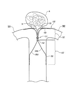
[0011] Figures 1A-1C are views of an aneurysm device 150 having a shock
absorbing
structure configured in accordance with an embodiment of the technology. In
particular,
Figure 1A is an isometric view of the aneurysm device 150 and Figure 1B is a
front view of
the device 150 outside of a patient, and Figure 1C is a partially schematic
view of the device
150 at a treatment site proximate to an aneurysm A in a patient.. Referring to
Figures 1A-1C
together, the aneurysm device 150 comprises a closure structure 152, one or
more shock
absorbing structures 101 (two are shown in the illustrated embodiment), and a
supplemental
stabilizer or support 153 extending from the closure structure 152 and the
shock absorbing
structures 101.
[0012] The closure structure 152 can be a frame, scaffold, or other
structure that at least
partially occludes the neck N of the aneurysm A to prevent embolic coils
(shown in Figure
1C) or other coagulative material within the aneurysm A from escaping into the
bloodstream.
The proximally-extending sides of the closure structure 152 and the
supplemental stabilizer
153 hold the curved portion of the closure structure 152 at the neck N of the
aneurysm A.
The closure structure 152 includes a perimeter support 160 and an inner
support 170. The
supports 160 and 170 can have a rhombus-like (e.g., diamond-shaped) shape or
configuration.
The perimeter support 160 and inner support 170 can be joined at junctions 162
and 164. The
aneurysm device 150 can also have struts 180a-d projecting proximally from the
junctions
162 and 164. Struts 180a-b are connected at junction 162 and struts 180c-d are
connected at
junction 164 to form the supplemental stabilizer 153 with proximal anchoring
segments.
-3-
CA 02837717 2013-11-28
WO 2012/167150 PCT/US2012/040552
[0013] In multiple device embodiments, the aneurysm device 150 may be
deployed
such that it is anchored along a specific portion of the neck N of the
aneurysm A. As shown
in Figure 1C, for example, the closure portion 152 of the aneurysm device 150
can bridge a
portion or all of the neck N and control blood flow into the aneurysm A. The
supports 160
and 170 can lodge in side branch vessels SB1 and SB2, while struts 180a-d can
press against
a wall of a parent vessel PV to collectively secure placement of the aneurysm
device 150. As
will be discussed in further detail below with reference to Figure 2, the
shock absorbing
structures 101 can smooth out or dampen movement of the aneurysm device 150
relative to
the blood vessel walls. Additionally, the shock absorbing structures 101 can
enhance the
junction of the closure structure 152 to the supplemental stabilizer 153 and
can improve the
aneurysm device's ability to withstand motion relative to the blood vessel
walls.
[0014] Figure 2 is a partially schematic illustration of the shock
absorbing structure
101. The shock absorbing structure 101 includes a shock absorbing assembly 220
distally
coupled to the junction 162 between the closure structure 152 and the
supplemental stabilizer
153. In the illustrated embodiment, the shock absorbing assembly 220 comprises
a leaf-
spring having a first spring aim 226a and a second spring arm 226b extending
laterally from
the junction 162. The first and second spring arms 226a and 226b can surround
an aperture
224. In further embodiments, the shock absorbing assembly 220 can include
other types of
springs or other shock-absorbing mechanisms. The supplemental stabilizer 153
can move
proximally, distally, and/or laterally relative to the closure structure 152
as the shock
absorbing assembly 220 contracts and expands.
[0015] .. A proximally-extending portion 232 of the closure structure 152 may
be coupled
to a distally-extending portion 222 of the shock absorbing structure 101 by an
attachment
feature 230. In some embodiments, the attachment feature 230 comprises a
solder
attachment. In further embodiments, however, other attachment mechanisms can
be used.
The flexibility provided by the shock-absorbing assembly 220 and the
attachment feature 230
is expected to inhibit movement of the supplemental stabilizer 153 relative to
a vessel wall
and help prevent movement in the blood vessel from dislodging the aneurysm
device 150
after deployment.
[0016] .. Figures 3 and 4 illustrate aneurysm devices having shock absorbing
structures
configured in accordance with additional embodiments of the technology. The
aneurysm
devices shown in Figures 3 and 4 include several features generally similar to
the aneurysm
device 150 described above with reference to Figure 1. Referring to Figure 3,
for example,
-4-
CA 02837717 2013-11-28
WO 2012/167150 PCT/US2012/040552
an aneurysm device 300 includes a closure structure 302 having a perimeter
support 310 and
an inner support 320. The shock absorbing structure 101 is located at a
proximal end of the
closure structure 302. The aneurysm device 300 further includes a supplemental
stabilizer or
support 303 extending from the shock absorbing structure 101. The shock
absorbing
structure 101 can enhance the junction of the closure structure 302 to the
supplemental
stabilizer 303 and can improve the aneurysm device's ability to withstand
motion within the
blood vessel.
100171 Referring now to Figure 4, an aneurysm device 400 includes a closure
structure
402 including a plurality of struts that form a perimeter support 410 and an
inner support 420.
The aneurysm device 400 includes shock absorbing structures 101 positioned on
a proximal
end of the closure structure 402 and coupled to a distal end of a supplemental
stabilizer 403.
The aneurysm device 400 further includes a barrier 440 that covers at least a
portion of the
perimeter support 410. In the particular embodiment illustrated in Figure 4,
the barrier 440
can be a membrane or other type of cover that extends across the full lateral
aspect of the
perimeter support 410 and a significant portion of the U-shaped curved region
of both the
perimeter support 410 and the inner support 420. The barrier 440 can enhance
the separation
between the cavity of an aneurysm and the lumen of the side branch vessels
compared to
aneurysm devices without the barrier.
Examples
1. An aneurysm device endovascularly deliverable to a site proximate to an
aneurysm near a parent artery with bifurcating downstream branches, the
aneurysm device
comprising:
a closure structure comprising a distal-facing aspect configured to at least
partially
occlude the aneurysm;
a supplemental stabilizer connected to the closure structure, the supplemental
stabilizer configured to reside in the parent artery and press outward against
a
luminal wall thereat and
a shock absorbing structure coupled to a proximal end portion of the closure
structure
and to a distal end portion of the supplemental stabilizer.
2. The aneurysm device of example 1 wherein the shock absorbing structure
comprises a spring.
-5-
CA 02837717 2013-11-28
WO 2012/167150 PCT/US2012/040552
3. The aneurysm device of example 2 wherein the spring comprises a leaf
spring
having a first spring arm and a second spring arm, and wherein the first and
second spring
arms at least partially surround an aperture.
4. The aneurysm device of example 3 wherein the first spring arm and the
second
spring arm extend laterally from at least one of the closure structure or the
supplemental
stabilizer.
5. The aneurysm device of example 2 wherein the supplemental stabilizer is
configured to move proximally, distally, and/or laterally relative to the
closure structure as
the shock absorbing assembly exhibits spring movement.
6 The aneurysm device of example 1, further comprising an attachment
feature
configured to couple the closure structure to the shock absorbing structure.
7. The aneurysm device of example 6 wherein the attachment feature
comprises
hardened solder.
8. The aneurysm device of example 1 wherein the shock absorbing structure
comprises a moveable junction between the closure structure and the
supplemental stabilizer.
9. A system for treating an aneurysm, the system comprising:
a distal framework portion comprising a distal-facing aspect configured to
enclose the
aneurysm;
a proximal support framework connected to the distal framework portion, the
support
framework configured to reside in a parent artery and biased to press outward
against a luminal wall thereof; and
a spring coupled to the distal framework portion and proximally movable
relative to
the distal framework portion.
10. The system of example 9 wherein the spring comprises a junction
connecting
the distal framework portion and the proximal support framework.
-6-
CA 02837717 2013-11-28
WO 2012/167150 PCT/US2012/040552
11. The system of example 9 wherein the spring comprises a leaf spring.
12. The system of example 9 wherein the distal framework portion comprises
a set
of distal struts forming at least one quadrilateral form with first and second
longitudinal
junctions, and wherein the system further comprises a barrier covering at
least a portion of
the distal struts.
13. The system of example 9 wherein the barrier comprises a membrane
configured to enhance a separation between a cavity of the aneurysm and the
parent artery.
14. A method of treating an aneurysm located at a site within a blood
vessel, the
method comprising:
positioning a framework comprising a distal portion and a proximal portion at
a site
proximate to the aneurysm;
applying a force outward from the proximal portion of the framework against a
luminal wall of the blood vessel; and
absorbing movement of the framework relative to the blood vessel with a shock
absorbing structure operably coupled with the framework.
15. The method of example 14 wherein absorbing movement of the framework
comprises dampening movement of the framework relative to a blood vessel wall
with the
shock-absorbing structure.
16. The method of example 14 wherein absorbing movement of the framework
comprises absorbing movement with a spring connecting the distal portion and
the proximal
portion.
17. The method of example 14 wherein absorbing movement of the framework
comprises inhibiting dislodgement of the framework relative to the aneurysm.
18. The method of example 14 wherein absorbing movement of the framework
comprises absorbing movement with a leaf spring.
-7-
CA 02837717 2013-11-28
WO 2012/167150 PCT/US2012/040552
19. The method of example 14 wherein absorbing movement of the framework
comprises absorbing movement of the distal portion relative to the proximal
portion.
20. The method of example 14, further comprising at least partially
occluding the
aneurysm with a barrier membrane coupled to the distal portion.
[0018] .. The above detailed descriptions of embodiments of the technology are
not intended
to be exhaustive or to limit the technology to the precise form disclosed
above. Although
specific embodiments of, and examples for, the technology are described above
for
illustrative purposes, various equivalent modifications are possible within
the scope of the
technology, as those skilled in the relevant art will recognize. For example,
while steps are
presented in a given order, alternative embodiments may perform steps in a
different order.
The various embodiments described herein may also be combined to provide
further
embodiments. In particular, the clot removal devices described above with
reference to
particular embodiments can include one or more additional features or
components, or one or
more of the features described above can be omitted.
[0019] From the foregoing, it will be appreciated that specific embodiments
of the
technology have been described herein for purposes of illustration, but well-
known structures
and functions have not been shown or described in detail to avoid
unnecessarily obscuring the
description of the embodiments of the technology. Where the context permits,
singular or
plural terms may also include the plural or singular term, respectively.
[0020] Moreover, unless the word "or" is expressly limited to mean only a
single item
exclusive from the other items in reference to a list of two or more items,
then the use of "or"
in such a list is to be interpreted as including (a) any single item in the
list, B all of the items
in the list, or (c) any combination of the items in the list. Additionally,
the term "comprising"
is used throughout to mean including at least the recited feature(s) such that
any greater
number of the same feature and/or additional types of other features are not
precluded. It will
also be appreciated that specific embodiments have been described herein for
purposes of
illustration, but that various modifications may be made without deviating
from the
technology. Further, while advantages associated with certain embodiments of
the
technology have been described in the context of those embodiments, other
embodiments
may also exhibit such advantages, and not all embodiments need necessarily
exhibit such
advantages to fall within the scope of the technology. Accordingly, the
disclosure and
-8-
CA 02837717 2013-11-28
WO 2012/167150 PCT/US2012/040552
associated technology can encompass other embodiments not expressly shown or
described
herein.
-9-