Note: Descriptions are shown in the official language in which they were submitted.
CA 02837744 2013-11-28
WO 2013/003111
PCT/US2012/043072
THROUGH TUBING EXPANDABLE FRAC SLEEVE WITH
REMOVABLE BARRIER
Inventors: Graeme Kelbie, Richard Yingqing Xu and Steve Rosenblatt
FIELD OF THE INVENTION
[0001] The field of the invention is fracturing techniques and more
particularly those techniques that replace bridge plugs that have to be milled
after the fracturing is completed with rapidly deployed expandable sleeves
with barriers removed after all zones are fractured.
BACKGROUND OF THE INVENTION
[0002] Fracturing methods commonly involve a technique of starting at
the well bottom or isolating a portion of the well that is not to be
perforated
and fractured with a plug. The first zone is then perforated and fractured and
then another plug is placed above the recently perforated zone and the process
is repeated in a bottom up direction until all the zones are perforated and
fractured. At the end of that process the collection of barriers are milled
out.
To aid the milling process the plugs can be made of non-metallic or composite
materials. While this technique is workable, there was still a lot of time
spent
to mill out even the softer bridge plugs and remove that milling debris from
the wellbore.
[0003] In the past there have been plugs used that are milled out as
described in USP 7,533,721. Some are forcibly broken to open a passage such
as in USP 6,026,903. Other designs created a plug with material that
responded to a magnetic field as the field was applied and removed when the
field was removed. This design was described in USP 6,926,089 and
6,568,470. In a multi-lateral application a plug was dissolved from within the
whipstock to reopen the main bore after the lateral was completed. This is
described in USP 6,145,593. Barriers that assist in extending telescoping
passages and then are removed for access to fracture the formation are
described in USP 5,425,424. Longitudinally extending radially expanded
packers to get them to release is shown in USP 7,661,470.
[0004] What is needed and provided by the present invention is a
fracturing system where thin sleeves with external seals, slips or anchors and
a
1
CA 02837744 2015-08-25
ball seat are run in and set in sequence. The next zone is perforated and a
ball is
landed on a seat and the just perforated zone is fractured. The process
repeats
until all the zones are fractured at which time the balls are removed from the
seats
preferably by dissolving them. The thin sleeves remain but are sufficiently
thin to
avoid materially impeding the subsequent production flow. The sleeves can be
run in with coiled tubing or wireline and expanded into sealing contact using
known setting tools that can, for example, push a swage through a sleeve to
expand the sleeve and the external seal that can be used with the sleeve.
Those
skilled in the art will better appreciate the various aspects of the invention
from a
review of the description of the preferred embodiment and the associated FIGS,
while appreciating that the full scope of the invention is to be found in the
appended claims.
SUMMARY OF THE INVENTION
[0005] Thin wall sleeves are inserted into a well and expanded into
sealing position to a surrounding tubular. Each sleeve has a ball seat. A zone
is
perforated after a sleeve is secured in position below the perforations. The
ball is
dropped onto the seat and pressure is built up to complete the fracturing.
After all
zones are perforated and fractured, the balls are removed, preferably by
dissolving
them and the thin walled sleeves are left in the tubular against which they
have
been expanded. Production can then begin from a selected zone. The objects can
be of the same size for each sleeve. The sleeves can be run through tubing and
into casing. Acid can be pumped to dissolve the objects.
[0005a] Accordingly, in one aspect there is provided a fracturing method
for a plurality of zones, the method comprising: perforating and fracturing a
first
zone; positioning adjacent said first zone at least one sleeve having an upper
and a
lower end and an open passage therethrough extending from said upper to said
lower end during said positioning; securing said sleeve to a surrounding
tubular by
expanding said passage; obstructing said passage with an object after said
securing; and fracturing at least a second zone with said passage obstructed.
2
CA 02837744 2015-08-25
[0005b] According to another aspect there is provided a fracturing method
for a plurality of zones, the method comprising: perforating and fracturing a
first
zone; positioning at least one sleeve having a passage therethrough adjacent
said
first zone; securing said sleeve to a surrounding tubular by expanding said
passage; obstructing said passage with an object; fracturing at least a second
zone
with said passage obstructed; providing a seat in said sleeve; expanding said
passage short of said seat; removing the object from said sleeve; producing
through said sleeve; and landing the object on said seat.
[0005c] According to another aspect there is provided a fracturing method
for a plurality of zones, the method comprising: perforating and fracturing a
first
zone; positioning at least one sleeve having a passage therethrough adjacent
said
first zone; securing said sleeve to a surrounding tubular by expanding said
passage; obstructing said passage with an object; fracturing at least a second
zone
with said passage obstructed; using a plurality of sleeves to separate
multiple
zones beyond said first zone; providing a seat in each sleeve; sequentially
dropping an object on a seat of a secured sleeve when a zone above it is ready
to
be fractured; removing the objects from said sleeves; producing through said
sleeves; using the same size object for each seat; and removing all objects
together
and after all the zones are perforated.
BRIEF DESCRIPTION OF THE DRAWINGS
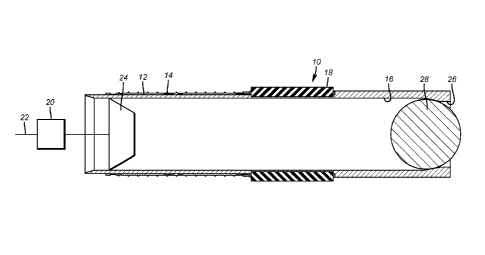
[0006] FIG. 1 is a section view of a thin wall sleeve in the set position
with a ball landed on the seat; and
[0007] FIG. 2 is the view of FIG. 1 with the ball removed from the seat.
DETAILED DESCRIPTION OF THE PREFERRED EMBODIMENT
[0008] FIG. 1 illustrates a sleeve 10 that is preferably a thin metal
tube
with slips 12 that have wickers 14 that are intended to penetrate the
surrounding tubular (not shown) when the sleeve 10 is expanded radially
outwardly from within the passage 16. A seal assembly 18 is also pushed
2a
CA 02837744 2013-11-28
WO 2013/003111
PCT/US2012/043072
against the surrounding tubular during the expansion. The delivery device can
be coiled tubing or wireline schematically illustrated as 22, to name a few
examples and the expansion device 20 can be one of a variety of known tools
that can advance an internal fixed or variable diameter swage 24. A
releaseable connection between the expansion device 20 and the sleeve 10 is
envisioned for initial retention of the two to each other for run in. As the
expansion of the sleeve starts the initial retainer (not shown) is broken and
that
initial expansion anchors the sleeve 10 so that the swage 24 can be advanced
by the expansion device that can include a combination of a resettable anchor
and a stroker that supports the swage 24.
[0009] The sleeve has a tapered ring-shaped ball seat 26 that is
intended to
receive an obstructing object such as a ball 28 to close off passage 16. The
ball
28 is dropped after the zone above a particular sleeve 10 has been perforated
and the gun dropped or removed from the wellbore. Once the gun is out of the
way and the zone perforated, the ball 28 can be dropped to land on seat 26 so
that pressure can be elevated from the surface and the newly perforated zone
above the sleeve 10 can be fractured. Once that fracturing is completed
another sleeve 10 can be run into a higher location or a location closer to
the
well surface and the process is repeated until all the zones in an interval
are
fractured. When the bottom up fracturing is completed a chemical is added to
the sleeve 10 as shown schematically by arrow 30 that will preferably react
with the ball 28 to break it up to the point that the passage 16 at seat 26 is
again clear. The ball 28 can be metallic or non-metallic and the added
material
can be a strong or weak acid or other material that will cause the ball 28 to
lose structural integrity or go into solution. Alternatively, the ball 28 in
each
deployed sleeve can be blown through one or more seats 26 although
dissolving the ball or breaking it up so that the debris can be removed from
the
wellbore is a preferred way to reopen each sleeve.
[0010] The inside dimension of passage 16 before expansion can be
constant or alternatively the upper segment that has the slips 12 and the seal
assembly 18 can have an initially smaller diameter for run in that is expanded
3
CA 02837744 2013-11-28
WO 2013/003111
PCT/US2012/043072
to the constant diameter as illustrated in FIG. 1 after the expansion is
completed. The expansion stops short of the ball seat 26.
[0011] Each sleeve can use the same ball size for ball 28 in the
preferred
bottom up method. An alternative possibility to remove the balls 28 is to blow
them through the ball seat 26. Alternatively the ball seat can be made of a
material that dissolves that is either the same as the material of the ball 28
so
that when both are removed only the wall thickness of the sleeve that is now
somewhat reduced due to its radial expansion is the sole reduction in the
drift
diameter from adding the sleeves 10. Alternatively each sleeve 10 can have
internal grooves above and below the slip 12 and the seal 18 that can be
grabbed with a tool to longitudinally extent the sleeve to get its diameter to
decrease for physical removal from the wellbore with the ball 28 as an
alternative to dissolving the ball and leaving the sleeve in place during
production.
[0012] The advantages over the known way of fracturing by zone from
bottom up should now be readily apparent to those skilled in the art. The
sleeves stay put and the passage in them is opened with preferably an addition
of a solvent to dissolve the balls on each seat and to further remove any
undissolved segments to the surface with circulation or reverse circulation.
The sleeves can be run through existing production tubing and expanded into
case below depending on the size differences between the two nest tubulars.
The initial wall thickness of the sleeve 10 needs to be strong enough after
expansion to withstand the tensile stress from pressure on the seated ball 28
during fracturing with the sleeve somewhat thinned out during expansion to
get the sleeve to be supported by the surrounding casing that has been
perforated above the expansion location for each sleeve. The sleeve material
has to be amenable to expansion without risk of cracks and should be
sufficiently compatible with well fluids to retain structural integrity
throughout the perforating and fracturing of all the zones that need to be
fractured. As another option the sleeve 10 material can also be made of a
dissolvable material so that dissolving the ball has an opportunity to remove
the sleeve and the seat and possibly the slip and seal assembly if they break
4
CA 02837744 2013-11-28
WO 2013/003111
PCT/US2012/043072
away from the surrounding tubular wall. If this happens the drift diameter
reduction from the sleeve and seat remaining behind can be further minimized.
[0013] The preferred initial wall thickness for a sleeve is initially
.25
inches and that wall thickness could be reduced by as under 5% due to
expansion depending on the percent expansion. The ability to deliver the
sleeves rapidly with a coiled tubing unit, if available, or with a wireline
that is
more economical and more readily deployable means less time consumed for
delivery of the sleeve for each zone to be fractured. The balls 28 can be
pumped down or simply dropped depending on the orientation of the wellbore.
While the preferred shape of the balls is a sphere, other objects that can
seat on
seat 26 such as wiper plugs or other elongated objects can also be used.
[0014] A big part of the time saving is not having to mill out the
bridge
plugs that used to be used to separate the zones for fracturing. The preferred
dissolving process is much faster and delivers a more certain drift diameter
after the fracturing than the milling process that can still leave some plug
components in the wellbore.
[0015] The above description is illustrative of the preferred embodiment
and many modifications may be made by those skilled in the art without
departing from the invention whose scope is to be determined from the literal
and equivalent scope of the claims below.