Note: Descriptions are shown in the official language in which they were submitted.
CA 02837768 2013-11-29
WO 2012/171127
PCT/CA2012/050404
AUTOMATED SIZE SELECTION OF NUCLEIC ACIDS
Reference to Related Application
[0001] This application claims Paris convention priority from United States
application
No. 61/497586 filed on 16 June 2011 and entitled Method and Apparatus for
Automated
Size Selection of Nucleic Acids which is hereby incorporated herein by
reference for all
purposes. For purposes of the United States of America, this application
claims the benefit
under 35 U.S.C. 119 of United States application No. 61/497586 filed on 16
June 2011
and entitled Method and Apparatus for Automated Size Selection of Nucleic
Acids which
is hereby incorporated herein by reference for all purposes.
Technical Field
[0002] This invention relates to the automated size selection of nucleic
acids. Aspects of
the invention provide methods and apparatus useful for selecting nucleic acids
according
to size.
Background
[0003] There are a wide range of applications in which it is desirable to
select nucleic
acids, such as DNA or RNA by size. For example, size selection is used in the
production
of DNA libraries for use in sequencing and other applications.
[0004] Various techniques for DNA size selection exist. Some of these
techniques are
undesirably labour intensive. One method for DNA size selection is to perform
electrophoresis of a sample containing DNA in a gel. Since DNA of different
sizes have
different mobilities in the gel the electrophoresis separates the DNA into
different bands
by size. A band containing DNA in the desired size range can be identified and
then
manually cut out from the gel. The desired DNA can then be extracted from the
gel.
[0005] Some electrophoresis systems comprise wells formed in a gel. DNA can be
run
into the wells by electrophoresis. Invitrogen E-gels and the Lonza Flash Ge1TM
provide
such wells.
[0006] Y-channel size selection machines are another technology for DNA size
selection.
Examples are the Sage Pippin PrepTM and the Caliper XTTm machines. These
machines
can extract DNA of a desired size range from a sample by diverting DNA of the
desired
size range into a side channel and collecting the diverted DNA against a
molecular weight
cut-off filter.
CA 02837768 2013-11-29
WO 2012/171127
PCT/CA2012/050404
- 2 -
[0007] Solid Phase Reversible Immobilization Beads (SPRI) beads which are
available
from Beckman Coulter and others may be used to trap DNA of a certain size and
then
release the DNA after a wash and a change in pH.
[0008] There remains a need for a DNA size-selection technology that can
provide high
throughput. There remains a need for a DNA size-selection technology that can
provide
accurate DNA size selection with reduced labour.
Summary
[0009] This invention has a number of aspects that may be applied together.
Some of the
aspects have independent application. One aspect provides apparatus for
automated size-
selection of nucleic acids. Another aspect provides a computer system for
controlling
apparatus for automated size-selection of nucleic acids. Another aspect
provides methods
for automated size-selection of nucleic acids. The nucleic acids may comprise
DNA and/or
RNA. Another aspect provides cartridges useful inter alia for automated size
selection of
nucleic acids.
[0010] In one example embodiment, nucleic acids are size selected by loading
DNA
samples individually into agarose channels, each of which has a loading well
at one end of
the channel and an extraction well downstream. Electrophoresis is performed on
the
nucleic acids after loading and the nucleic acids are separated by size as
they migrate
towards the extraction well. The channel is imaged at regular intervals during
this process
and a software algorithm uses the images to identify reference bands and
predict the time
at which the desired nucleic acid fragments will arrive at the extraction
well. The channel
current is also individually controllable via pulse width modulation of the DC
voltage so
that if adjacent samples are running at different speeds, the extractions
times can be altered
so that no two samples need to be extracted at the same moment.
[0011] Another aspect of the invention provides methods for size-selection of
nucleic
acids such as DNA, RNA and the like. Such methods comprise moving nucleic
acids from
a sample along a channel by electrophoresis; automatically monitoring progress
of a
reference fraction of the nucleic acids along the channel; based on the
monitoring,
estimating an estimated time of arrival of a target fraction of the nucleic
acids at an
extraction well in the channel; and extracting fluid containing the target
fraction from the
extraction well at the estimated time of arrival. The reference fraction may
be the same as
or different from the target fraction. For example, in some embodiments the
reference
CA 02837768 2013-11-29
WO 2012/171127
PCT/CA2012/050404
- 3 -
fraction may comprise nucleic acids that are abundant in the sample (either
originally
present in the sample or added to the sample as a size marker) and the target
fraction may
comprise nucleic acids having sizes different from that of the reference
fraction. Progress
of the target fraction along the channel may be inferred from progress of the
reference
fraction. For example, the target fraction may be known to lead or lag behind
the reference
fraction by a certain percentage. In some embodiments, the target fraction of
the nucleic
acids comprises an adapter joined to a nucleic acid molecule of interest, and
the reference
fraction of the nucleic acids comprise the adapter which is not joined to the
nucleic acid
molecule of interest. In some embodiments, the methods may comprise
automatically
monitoring progress of a plurality of reference fractions of the nucleic acids
along the
channel. The plurality of reference fractions may comprise a DNA or RNA ladder
of
known sizes.
[0012] In some embodiments the monitoring comprises, at spaced apart times,
obtaining
images of the channel and identifying areas in the images corresponding to the
reference
fraction. The images may, for example, be acquired by a camera mounted to view
the
channel. The camera may image a large number of channels simultaneously.
Progress of
the reference fractions (which are not necessarily the same for different
channels) in
multiple channels may be monitored using the same set of images. The estimated
time of
arrival of the target fraction may be estimated in some cases based on an
average velocity
of the target fraction based on differences between the positions of the
reference fraction in
two or more of the images. The images may comprise high dynamic range images.
For
example, the images may be obtained using a high dynamic range sensor or may
be
assembled from two or more different exposures. In some embodiments the images
have a
bit-depth of 10-bits or 12-bits or more. In some embodiments obtaining each of
the images
comprises operating an imaging device to obtain a plurality of different
exposures of the
channel and combining the plurality of different exposures to yield the image,
wherein the
image has a greater dynamic range than any of the plurality of different
exposures.
[0013] Some embodiments comprise specifying a size or size range of the target
fraction.
For example, the size or size range of the target fraction may be specified in
absolute terms
or relative to one or more of the reference fractions. For example, the size
or size range of
the target fraction may be specified as leading or lagging behind the
reference fraction by a
certain percentage. Some embodiments comprise scheduling a time of arrival for
the
target fraction at the extraction well; comparing the scheduled time of
arrival to the
estimated time of arrival and adjusting one or more electrophoresis parameters
of an
CA 02837768 2013-11-29
WO 2012/171127
PCT/CA2012/050404
- 4 -
electrophoresis signal based on any difference between the scheduled time of
arrival and
the estimated time of arrival. In such embodiments, target fractions in
different channels
may be caused to arrive at extraction wells at different times (facilitating
extraction of the
target fractions using a single mechanism such as a robot carrying a pipetter
that services
each channel at the scheduled time). Also in such embodiments target fractions
in different
channels may be caused to arrive at extraction wells at the same time
(facilitating
extraction of the target fractions using a multi-channel mechanism such as a
robot carrying
a multi-channel pipetter that services several channels simultaneously at the
scheduled
time).
[0014] Adjusting the one or more electrophoresis parameters may comprise
adjusting a
duty cycle of the electrophoresis signal, adjusting potentials of the
electrophoresis signal or
adjusting other parameters that define the electrophoresis signal.
[0015] In some embodiments the method determines a location of an extraction
well
and/or a loading well in one or more channels by image analysis. This
facilitates systems
in which extraction wells in different channels are at different locations and
also facilitates
automatic compensation for variations in the positions of extraction wells
and/or loading
wells.
[0016] Another aspect of the invention provides apparatus for size-selection
of nucleic
acids. The apparatus comprises: a channel having first and second ends and an
extraction
well in the channel; an electrophoresis power supply connected to deliver an
electrophoresis signal to the channel to move nucleic acids from a sample
along the
channel; an imaging device mounted to image the channel; a controller
connected to obtain
images from the imaging device, the controller is configured to: automatically
monitor
progress of a reference fraction of the nucleic acids along the channel by
analysis of the
images; based on the monitoring, estimate an estimated time of arrival of a
target fraction
of the nucleic acids at the extraction well in the channel; and operate a
mechanism to
extract fluid containing the target fraction from the extraction well at the
estimated time of
arrival.
[0017] The imaging device may comprise an electronic camera. The camera may be
equipped with a filter that attenuates light outside of an emission band of a
dye associated
with the nucleic acid.
CA 02837768 2013-11-29
WO 2012/171127
PCT/CA2012/050404
- 5 -
[0018] In some embodiments the mechanism comprises a robotic system comprising
a
pipetter operable to transfer a sample into a loading well in the channel and
to extract the
fluid from the extraction well. In some embodiments the pipetter comprises a
multi-
channel pipetter capable of simultaneously introducing multiple samples into
multiple
channels or simultaneously extracting fluids from extraction wells in multiple
channels.
[0019] In some embodiments the channel comprises an elongated groove having
opposed
first and second sides and an electrophoresis medium in the groove and the
first and
second sides having steps extending longitudinally along the first and second
sides, the
electrophoresis medium filling the groove up to the steps.
[0020] The electrophoresis medium may comprise, for example, a gel such as an
agarose
gel, an acrylamide gel, a denaturing acrylamide gel, or the like.
[0021]In some embodiments the controller is configured to determine a location
of the
extraction well in the channel by image analysis of one or more of the images
and to move
the pipette tip to the determined location of the extraction well.
[0022] In some embodiments the controller is configured to compare the
estimated time of
arrival of the target fraction at the extraction well to a desired time of
arrival of the target
fraction at the extraction well and to control the electrophoresis power
supply to adjust
one or more electrophoresis parameters of the electrophoresis signal based on
any
difference between the desired time of arrival and the estimated time of
arrival.
[0023] In some embodiments the controller is configured to control a rate of
movement of
the nucleic acids along the channel by proportional feedback control of the
one or more
electrophoresis parameters based on an error signal comprising a difference
between the
estimated time of arrival and a desired time of arrival of the target fraction
at the extraction
well.
[0024] In some embodiments the controller comprises a scheduler configured to
generate
the desired time of arrival of the target fraction at the extraction well.
[0025] The apparatus may comprise a proportional feedback controller
configured to
control the electrophoresis power supply to vary an average speed of the
target fraction
along the channel in response to an error signal representing a difference
between the
CA 02837768 2013-11-29
WO 2012/171127
PCT/CA2012/050404
- 6 -
estimated time of arrival of the target fraction at the extraction well and a
desired time of
arrival of the target fraction at the extraction well. In some embodiments the
controller is
configured to reduce a difference between the estimated arrival time and the
desired arrival
time by temporarily interrupting application of the electrophoresis signal to
the channel.
[0026] Another aspect of the invention provides a cassette for use in size
selection of
nucleic acids. The cassette comprises a plate having a channel formed in the
plate, the
channel comprising an elongated groove having opposed first and second sides
and an
electrophoresis medium in the groove, first and second sides having steps, the
electrophoresis medium filling the groove up to the steps. The plate may have
one or more
holes, grooves or other features for locking the plate into a known location
relative to a
robot. The channel may include both a loading well and an extraction well at
spaced apart
locations along the channel. The plate may optionally be transparent at least
in its portion
below the channel.
[0027] Further aspects of the invention and features of example embodiments of
the
invention are illustrated in the accompanying drawings and/or described below.
Brief Description of the Drawings
[0028] The accompanying drawings depict non-limiting example embodiments of
the
invention.
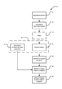
[0029] Figure 1 illustrates a method for size-selecting a nucleic acid
according to an
example embodiment.
[0030] Figure lA illustrates an alternative example method.
[0031] Figure 2 illustrates schematically an image of one channel.
[0032] Figure 2A is a plot illustrating density as a function of position
along channel.
[0033] Figure 3 illustrates a method for identifying a peak corresponding to
DNA of a
predetermined size.
[0034] Figure 4 illustrates apparatus according to an example embodiment.
CA 02837768 2013-11-29
WO 2012/171127
PCT/CA2012/050404
- 7 -
[0035] Figure 5 shows an example robot.
[0036] Figure 5A shows an example deck.
[0037] Figure 5B shows an example camera assembly.
[0038] Figure 6 is a screen shot of an example graphical display.
[0039] Figure 7 is a plan view of an example channel plate.
[0040] Figure 7A is a cross section of an individual channel.
[0041] Figure 7B shows an example comb useful for forming loading or
extraction wells.
[0042] Figure 7C is a plan view of an example channel plate according to
another
embodiment.
[0043] Figure 7D is a perspective view of a channel plate with combs engaged
for forming
source and extraction wells.
Description
[0044] Throughout the following description specific details are set forth in
order to
provide a more thorough understanding to persons skilled in the art. However,
well
known elements may not have been shown or described in detail to avoid
unnecessarily
obscuring the disclosure. Accordingly, the description and drawings are to be
regarded in
an illustrative, rather than a restrictive, sense.
[0045] One aspect of the invention provides an automated method for size
selection of
multiple nucleic acid samples. The method uses imaging in conjunction with
predictive
algorithms to time extractions and provide size selected nucleic acids of a
desired size
range. The method can be practiced to advantage in conjunction with automated
apparatus
comprising one or more electrophoresis channels, a camera which acquires
images of the
one or more electrophoresis channels and a robot comprising a pipetter for
introducing
samples into corresponding channels and extracting size-selected nucleic acids
from the
channels. The channels may be filled, for example, with an agarose gel or an
acrylamide
CA 02837768 2013-11-29
WO 2012/171127
PCT/CA2012/050404
- 8 -
gel. The channels may each have a loading well in the channel and an
extraction well
spaced apart from the loading well along the channel.
[0046] The following description explains construction and operation of
example
embodiments being used to size-select DNA. For example, the DNA may comprise
cDNA
derived from RNA. The DNA to be size-selected may have a size in the range of
10 bp to
kbp. However, the invention may be applied to size-selection of other nucleic
acids
such as RNA. In some embodiments the nucleic acids comprise sheared nucleic
acids.
10 [0047] Figure 1 illustrates a method 10 according to an example
embodiment of the
invention. In block 11 a sample containing DNA is introduced into a loading
well in a
channel containing a medium through which the DNA can be moved by
electrophoresis.
The sample containing the DNA may also comprise a dye (e.g., SYBR GreenTM dye
or
ethiclium bromide) which is introduced into the loading well together with the
DNA. The
function of the dye is to facilitate the detection or imaging of the DNA in
the medium. In
some embodiments, the DNA molecules in the sample may comprise an adapter,
which
may be useful for downstream applications such as DNA sequencing. The medium
may,
for example, comprise an agarose or acrylamide gel. In block 12
electrophoresis is
commenced. Electrophoresis may be performed by applying an electrical
potential
difference between electrodes at opposing ends of the channel. The potential
difference
may comprise a DC electrical potential, a pulsed DC electrical potential or an
unbalanced
AC electrical potential, for example. The applied electrical potential drives
the DNA to
migrate from the loading well along the channel toward an extraction well. DNA
of
different sizes has different mobilities in the channel and so the DNA becomes
size
segregated.
[0048] Optional block 13 provides a delay to allow the DNA to migrate far
enough along
the channel that concentrations of DNA of different sizes can be detected.
Block 14
comprises determining the location along the channel of target DNA of a
desired size
range. In some embodiments, block 14 comprises obtaining a sequence of images
of the
channel with a camera, detecting one or more landmarks in the image(s)
corresponding to
DNA of one or more known sizes, and determining the position of the target DNA
based
on the position(s) of the landmark(s). The output of block 14 is a sequence of
positions
along the channel of the target DNA.
CA 02837768 2013-11-29
WO 2012/171127
PCT/CA2012/050404
- 9 -
[0049] Sizing reference(s) (e.g. landmarks) may be specified at or before run
time;
whether it is a DNA ladder, or an inherent feature expected to be present in
the
electropherogram. If the size reference used is a DNA ladder, the DNA ladder
may be
added to the sample prior to loading the sample into the loading wells. In
some
embodiments, the size reference is inherently present in the sample. For
example, to size-
select a cDNA sample derived from miRNA, the sample may comprise both
cDNA+adapter fragments (e.g., having a size of 109 bp) as well as adapter-
adapter
fragments (e.g., having a size of 80 bp). The adapter-adapter fragments may be
used as a
size reference.
[0050] The size-range of the target DNA may be specified in various ways, for
example in
absolute terms or relative to given reference(s), allowing for excision of
fractions with
sizes either dependent or independent of the electropherogram profile of the
input sample.
For example, if the input sample is sheared genomic DNA with an expected peak
centre at
¨250bp, the mobility range of the target fraction may be specified relative to
the peak
centre (e.g. 110%- 90% of the peak-centre mobility), or the target may be
specified as a
absolute size range (e.g. 150bp-200bp) independent of the actual mobility of
the peak
centre.
[0051] Block 15 determines an average velocity of the target DNA along the
channel.
Block 15 may, for example, be as simple as dividing a difference of two
positions of the
target DNA by an elapsed time between the images from which the positions were
determined. Block 15 may take into account more than two positions. For
example, block
15 may average or find the median of a plurality of velocities.
[0052] Block 16 estimates a time of arrival of the target DNA at the
extraction well. This
determination may be based on a known, predetermined location of the
extraction well. In
some embodiments the location of the extraction well is determined in block 17
by
locating the image of the extraction well in the images obtained in block 15
(or else
separate images obtained for the purpose of locating the extraction well).
This image
recognition may be model-based (i.e. it is known in advance what the image of
a channel
is expected to look like in an image, where each channel is expected to be
found in the
image, and what the image of an extraction well is expected to look like in
the image.
Locating the extraction well may, for example, comprise, finding a location in
the image
where the correlation with a model image of an extraction well is maximized.
In other
CA 02837768 2013-11-29
WO 2012/171127
PCT/CA2012/050404
- 10 -
simpler embodiments locating the extraction well in the image comprises
locating one or
more edges corresponding to the extraction well in the image.
[0053] For example, the estimated time of arrival may be obtained by adding an
estimated
travel time to a current time. The estimated travel time may be determined,
for example,
by dividing a distance between the location of the extraction well and the
current location
of the target DNA by the current velocity of the target DNA as estimated in
block 15.
[0054] Block 18 extracts the target DNA from the extraction well at the
estimated arrival
time. Block 18 may, for example comprise controlling a robot carrying a
pipetter to place
the pipetter into the extraction well at or before the estimated arrival time
and withdrawing
fluid from the extraction well into the pipetter at the estimated arrival
time. The robot may
then dispense the collected fluid into a reservoir where the fluid may be held
or delivered
for further processing.
[0055] Method 10 has a range of variations. In some embodiments information
regarding
the velocity and/or position of the target DNA is applied to control the
velocity of target
DNA. Position information obtained from run-time electropherograms and time
information is used in a feedback loop to control electrophoresis speed of the
target DNA
fraction in addition to its arrival time at the extraction well.
[0056] Feedback control may be applied, for example, to adjust the estimated
arrival time
of the target DNA at the extraction well. The estimated arrival time may be
adjusted, for
example, adjusting a duty cycle and/or voltage of an electrophoresis field
and/or by
pausing application of the electrophoresis field one or more times.
Embodiments which
adjust velocity of the target DNA by adjusting duty cycle can be advantageous
since the
relationship between duty cycle and velocity tends to be linear or nearly
linear. This
simplifies control. Electrophoresis speed and extraction scheduling may be
simultaneously
controlled for an arbitrary number of samples. In one embodiment, extraction
scheduling
processes 96 samples running in parallel.
[0057] Figure lA illustrates an alternative example method 10A which is
similar to
method 10 except that it includes a block 19 that schedules a scheduled
arrival time for the
target DNA and a block 20 that compares the estimated arrival time from block
16 to the
scheduled arrival time for the target DNA. Block 21 receives a control signal
from block
20 and adjusts electrophoresis parameters based on the control signal. Loop 22
may be
CA 02837768 2013-11-29
WO 2012/171127
PCT/CA2012/050404
- 11 -
repeated periodically at a rate sufficient to control the progress of the
target DNA so hat
the target DNA arrives at the extraction well at the scheduled time.
[0058] In block 21, the electrophoresis parameters may be adjusted, as
appropriate, to
retard the progress of the target DNA, to accelerate the progress of the
target DNA or to
maintain the current rate of progress of the target DNA. In some embodiments
the
adjustment depends merely on the sign of the control signal (i.e. whether the
estimated
arrival time is before or after the scheduled arrival time). In other
embodiments the
adjustment is based at least in part on a magnitude of the difference between
the estimated
arrival time and the scheduled arrival time (or equivalently a magnitude of
the difference
between an estimated velocity and a velocity that would result in the target
DNA arriving
at the extraction well at the scheduled time.
[0059] In typical cases the target DNA does not have a specific size but has a
range of
sizes. Thus the target DNA will arrive at an extraction well during a time
window having a
length determined by the range of sizes in the DNA fraction as well as by the
electrophoresis parameters. In some embodiments a target fraction may be
specified
initially and also continuously adjusted until the fraction is extracted.
[0060] Control over the time at which target DNA arrives at an extraction well
may be
applied to good effect in the case where multiple electrophoresis channels are
being
operated at the same time. For example, electrophoresis of DNA in each of a
plurality of
channels may be controlled to cause target DNA in each channel to arrive at an
extraction
well at a scheduled time such that the scheduled times in different channels
are different.
The target DNA in different channels may be the same or different. This can
facilitate
using a robot to extract target DNA from each of the channels without
requiring the same
pipetter of the robot to be extracting fluid from two extraction wells at the
same time. The
scheduled times may be assigned to ensure that there is enough time for the
robot to make
each of the scheduled extractions.
[0061] Control over the electrophoresis velocity may be applied to compensate
for
variations between channels in electrophoresis velocity (caused, for example,
by
inhomogeneities in the electrophoresis medium or other differences in the
electrophoresis
medium used in different channels. The control may also be applied to
compensate for
differences in the location of the extraction well between channels. The
control may also
be applied to compensate for differences in the target DNA for different
channels.
CA 02837768 2013-11-29
WO 2012/171127
PCT/CA2012/050404
- 12 -
[0062] Some embodiments employ a multi-channel robot. For example, such a
robot may
have a plurality of pipetters arranged so that their tips can be
simultaneously inserted into a
plurality of extraction wells. For example, the robot may carry 8, 16 or some
other number
of pipetters. In some such embodiments channels are arranged side-by-side and
the robot
may be configured to simultaneously introduce fluid into N adjacent loading
wells or to
simultaneously remove fluid from N adjacent extraction wells.
[0063] In some embodiments which use a multi-channel robot, electrophoresis in
a
plurality of channels is controlled to cause target DNA in the plurality of
channels to reach
extraction wells at the same scheduled time. The target DNA may differ among
the
plurality of channels. The robot may then be controlled to place pipette tips
into the
extraction wells of the plurality of channels at the scheduled time and to
simultaneously
extract fluid from the extraction wells. Such embodiments permit different
scheduled
arrival times to be assigned to groups of channels. Electrophoresis in the
individual
channels in each group may be separately controlled to cause target DNA in
each channel
in the group to arrive at the corresponding extraction well at the time
scheduled for that
group. The scheduled times for different groups of channels may be spaced
apart such that
the robot has time to make the scheduled extractions. Such embodiments can
provide high
throughput electrophoresis.
[0064] The principles described above may also be applied in situations where
it is desired
to extract two or more fractions from the same sample. For such applications,
electrophoresis may be performed to bring a first target fraction to an
extraction well and
to extract the first target fraction. Subsequently, further electrophoresis
may be performed
to bring a second fraction to the extraction well. The second fraction may
then be
extracted. If desired, the first and second target fractions may be kept
isolated from one
another. For example, each of the first and second target fractions may be
transferred from
the extraction well to a separate destination well. It is also possible to
transfer multiple
fractions from the same sample to the same destination well if that is
desired.
[0065] In some applications, three or more fractions may be extracted from the
same
sample. Where two or more target fractions are to be extracted from the same
sample then
extraction of each of the target fractions may be separately scheduled. After
a first target
fraction has been extracted from a channel at a first scheduled time,
electrophoresis
CA 02837768 2013-11-29
WO 2012/171127
PCT/CA2012/050404
- 13 -
parameters for the channel may be controlled to bring the second target
fraction to the
extraction well for extraction at a second scheduled time.
[0066] In some embodiments electrophoresis is controlled in a plurality of
channels to
bring a corresponding plurality of first target fractions to the extraction
wells in the
plurality of channels at a first time. A multi-channel pipetter or other multi-
channel
extraction mechanism may then be applied to transfer the first target
fractions to
corresponding destination wells. Electrophoresis in the plurality of channels
may then be
controlled to bring second target fractions to the extraction wells in the
channels at the
same time. It is not necessary that the spacing between the first target
fractions and the
second target fractions be the same between the different channels.
Electrophoresis may be
controlled to move the second target fraction toward the extraction well
faster in some
channels than in others. In some embodiments electrophoresis is controlled to
bring the
second target fractions to extraction wells at the same time in the plurality
of channels so
that the second target fractions can be simultaneously extracted using the
multi-channel
pipetter.
[0067] Figure 2 illustrates schematically an image of one channel 24. Channel
24
comprises a strip 25 of a suitable electrophoresis medium with a buffer
reservoir 25A, 25B
at each end. A loading well 26A is located in medium 25 near buffer reservoir
25A. An
extraction well is located in medium 25 at a location that is spaced apart
from loading well
26A toward buffer reservoir 25B.
[0068] Also shown in Figure 2 are various bands of DNA that have been carried
along
medium 25 from loading well 26A by electrophoresis. Because DNA of different
sizes
moves at different rates under electrophoresis, the bands at different
locations represent
DNA of different sizes. Different bands may have different densities in the
image. The
bands may all represent DNA that is present in a sample. In some embodiments
DNA of a
known size or a set of known sizes (e.g. a DNA ladder) may be added to the
sample for the
purpose of providing a size scale that may be used to determine the location
of target
DNA.
[0069] In some embodiments sizing references such as DNA ladders are run in
the same
channel 24 as input samples. This ensures sizing accuracy in comparison to
embodiments
where sizing references and samples are run in separate channels.
CA 02837768 2013-11-29
WO 2012/171127
PCT/CA2012/050404
- 14 -
[0070] Figure 2A is a plot illustrating density as a function of position
along channel 24.
Peaks in curve 27 correspond to the locations of the bands shown in Figure 2.
The
methods described above may identify a peak in curve 27 corresponding to the
target DNA
or infer a current position of the target DNA from locations of one or more
other peaks
corresponding to DNA having a known size relationship(s) to the target DNA.
[0071] Some embodiments provide a scheduler. The scheduler may, for example,
be
implemented in software. The scheduler may schedule: the transfer of samples
into source
wells 26A in channels 24, commencement of electrophoresis in channels 24 and
the
extraction of target fractions from extraction wells 26B. In some embodiments
the
scheduler operates while samples are being run in channels 24 and may re-
schedule
extraction of target fractions in response to the monitoring of the progress
of the target
fraction (or a band having a known relationship to the target fraction). The
schedule may
initially schedule extraction of a target fraction in a time-slot that is
separated from a time
of commencement of electrophoresis in a channel by a period that is longer
than the
shortest period in which a target fraction could possibly progress from the
source well 26A
to the corresponding extraction well 26B. The time period used for this
initial scheduling
may be determined based on a measured distance from the source well 26A to the
extraction well 26B in some embodiments. The time period may be generated
based on an
assumed average velocity of the target fraction that is less than a maximum
velocity
achievable within an available range of electrophoresis parameters. The
assumed average
velocity may be a function of a size of the target fraction and the
characteristics of the
medium in which electrophoresis is being performed.
[0072] In some embodiments, the length of a period scheduled by the scheduler
for
extraction of a target fraction is variable and depends on the sizes of
nucleic acid included
in the target fraction (a target fraction which includes a greater range of
sizes will take
longer to extract than a target fraction in which the spread of sizes is
small). In some
embodiments start and stop times for extraction of a target fraction are
adjusted on the
basis of the estimated times of arrival at the extraction well of leading and
trailing edges of
the target fraction.
[0073] In some embodiments the scheduler monitors for conflicts between times
for
extraction of target fractions from different channels 24. In some such
embodiments, in the
case of a conflict (i.e. periods assigned to extraction of target fractions
from different
channels 24 overlap the scheduler may revise the scheduled time for extraction
of the
CA 02837768 2013-11-29
WO 2012/171127
PCT/CA2012/050404
- 15 -
target fraction from one of the channels 24 to remove the conflict. Changing
of the
scheduled extraction time may automatically result in parameters of the
electrophoresis in
the rescheduled channel 24 being altered so as to control the progress of the
target fraction
in the channel 24 so that the target fraction arrives at the extraction well
at the rescheduled
time.
[0074] In some embodiments the electrophoresis parameters for a channel 24 are
controlled such that upon the leading edge of the target fraction arriving at
the
corresponding extraction well 26B and extraction commencing, the rate of
electrophoresis
is increased, thereby reducing the time over which extraction must be
continued to extract
the entire target fraction.
[0075] Figure 3 illustrates a method 30 for identifying a peak corresponding
to DNA of a
predetermined size in channel 24. Block 32 applies electrophoresis to a
channel using
known electrophoresis parameters for a period of time. Block 33 obtains an
image of the
channel at the end of block 33. Block 34 identifies a range of positions along
the channel
based upon known characteristics for the target DNA. For example, a
predetermined
calibration curve 35 may be provided which relates position along the channel
to DNA
size. In some embodiments a plurality of different calibration curves 35 are
provided. The
different calibration curves may apply to different media that may be used in
channels 24.
[0076] Block 34 estimates a position or range of positions in which target DNA
is
expected to be found. The estimated position may be a function of the length
of time that
electrophoresis has been performed, the medium in channel 24, the
electrophoresis
parameters and the characteristics (especially size) of the target DNA. An
operator may
enter a size or size range for the target DNA. Block 34 may use an appropriate
calibration
curve 35 to identify the expected position of a peak in curve 27 corresponding
to the target
DNA. Block 36 sets a range 37 (see Figure 2A) and searches curve 27 for a peak
within
range 37. If a peak is successfully detected (as determined e.g. by a YES
result from block
39 then the peak is identified as the initial location of the target DNA. Once
a peak
corresponding to target DNA has been identified in one image the peak may be
tracked
through subsequent images as it propagates along the channel. Prominent
features of the
electropherogram profile may be identified at run-time and used to help
maintain size
integrity as faster-moving size references move out of the field of view.
CA 02837768 2013-11-29
WO 2012/171127
PCT/CA2012/050404
- 16 -
[0077] Method 30 may be applied to identify one or more peaks corresponding to
DNA in
a DNA ladder and/or a sample. In some embodiments one or more peaks that are
different
from the target DNA are identified and tracked as described above. A current
location of
the target DNA may be identified relative to such peaks. For example, a user
may specify
the amount by which target DNA is expected to lead or lag one or more such
peaks.
[0078] Figure 4 illustrates apparatus 40 according to an example embodiment.
Apparatus
40 comprises a robot 42 comprising a pipetter 44 that can be positioned by
robot 42 over
desired locations in a field 43. For example, robot 42 may comprise an XYZ
stage that
supports a single-channel pipette pump, which also supports a buffer loading
line and tip
ejection mechanism. A source plate 45 comprises a plurality of source wells
45A. A
destination plate 46 comprises a plurality of destination wells 46A. A
plurality of channels
47 is provided within field 43.
[0079] Robot 42 comprises a controller 42A that can control the position of
pipetter 44.
Controller 42A may, for example, control robot 42 to load a channel by:
picking up a
pipette tip 48 at a station 48A, positioning the pipette tip over a selected
source well 45A,
lowering the pipette tip into the source well 45A and drawing fluid into the
pipette tip
45A, raising the pipette tip and repositioning it over a loading well of a
selected channel
47, lowering the pipette tip into the loading well, operating the pipetter to
dispense the
fluid into the source well, raising the pipette tip and moving to pipette tip
to a storage area
for used pipette tips and disconnecting the used pipette tip.
[0080] Controller 42A may, for example, control robot 42 to retrieve target
DNA from a
channel by: picking up a pipette tip 48 at station 48A, positioning the
pipette tip over the
extraction well in the selected channel, just prior to the estimated arrival
of the target DNA
lowering the pipette tip into the extraction well of the channel, drawing
fluid into the
pipette tip 45A over a period of time corresponding to the expected arrival of
the target
DNA, raising the pipette tip and repositioning it over a destination well 46A,
lowering the
pipette tip into the destination well, operating the pipetter to dispense the
fluid into the
destination well, raising the pipette tip and moving to pipette tip to a
storage area for used
pipette tips and disconnecting the used pipette tip.
[0081] Apparatus as described herein may be configured to process any sensible
number
of samples. In some embodiments, apparatus as described herein provides
automated size
selection for 96 samples concurrently. In other example embodiments apparatus
process
CA 02837768 2013-11-29
WO 2012/171127
PCT/CA2012/050404
- 17 -
multiples of 96 samples concurrently. Other example embodiments are configured
to
process other numbers of samples.
[0082] Robots suitable for use as robot 42 are commercially available. Robots
suitable for
use as robot 42 may also be made from commercially-available components in
ways
known to those of skill in the art.
[0083] Apparatus 40 comprises an imaging device 50 which may, for example,
comprise a
camera arranged to obtain images of channels 47. Imaging device 50 may
comprise a high
dynamic range imaging device. For example, camera 50 or a controller connected
to
receive images from camera 50 may be configured to obtain and combine images
taken at
different exposure times to expand the detectable dynamic range. This allows
dim bands to
be visible without saturating the brightest bands.
[0084] A light source 52 illuminates channels 47 to facilitate imaging of
nucleic acids
propagating along the channels. Where the DNA is associated with a dye the
light source
may emit light corresponding to an absorption band of the dye (e.g. a band
corresponding
to a wavelength that excites a fluorophore of the dye. Light source 52 may
comprise a
filter that blocks wavelengths outside of this range. For example, SYBR Green
Tm dye
absorbs light at 488nm. The light source may emit blue light. For example, the
light source
may comprise an array of blue LEDs. Alternatively or additionally, the light
source may
emit UV light. Camera 50 may include a filter that preferentially admits
fluorescence of
the dye. for example, SYBR GreenTM dye emits light at 520nm. The camera may
have a
bandpass or notch filter that passes light at 520 nm but attenuates light at
other
wavelengths.
[0085] For example, the camera may be fixed to a component of robot 42 such
that the
camera is at a fixed distance from channels 47. In a prototype embodiment
camera 50 and
LED illuminator 52 are fixed to a Y-axis arm of robot 42.
[0086] A multi-channel electrophoresis power supply 54 is configured to
provide
electrophoresis potentials across channels 47.Power supply 54 may comprise a
single unit
or a plurality of separate units. A controller 55 is connected to receive
images from camera
50 to control power supply 54 and to coordinate actions of robot 42. A user
interface 56
allows users to provide control inputs and information to guide operation of
apparatus 40.
CA 02837768 2013-11-29
WO 2012/171127
PCT/CA2012/050404
- 18 -
[0087] In operation of an example system, source and destination plates 45, 46
are loaded
along with two tip boxes containing pipette tips. Plates comprising channels
47 are set on
the deck and electrode arrays are placed so that their electrodes are in
electrical contact
with channels 47 in the ends of the channel plate. In some embodiments the
electrodes are
mounted to a structure which permits them to be introduced into buffer wells
at each end
of each channel. For example, the apparatus may comprise a hinged frame
carrying first
and second electrodes corresponding to each channel. The first and second
electrodes may
be mounted on the hinged frame and the hinged frame may be movable between a
first
position wherein the first and second electrodes project into first and second
buffer
reservoirs of a channel and a second position wherein the first and second
electrodes are
removed from the first and second buffer reservoirs.
[0088] The control software is configured with the location of the samples (a
whole 96
well plate or less or more), type of samples and positions of the channel
plate(s).
[0089] When a run commences, buffer wells in the channel plates are filled.
The samples
are loaded sequentially (e.g. by the robot into the loading wells in channels
47) and
electrophoresis commences. In one embodiment, the on board camera 50 is used
to locate
the extraction well in each channel 47 avoiding the requirement to manually
configure the
location of the extraction wells. This facilitates the possibility of
providing extraction
wells at different locations within their channels 47.
[0090] Some embodiments comprise a mechanism for measuring and/or setting the
Y
position of the pipette tip. Knowing the exact position of the pipette tip
facilitates precise
loading and retrieval of nucleic acid samples in small wells. Such a mechanism
is useful
because the ends of different pipette tips can be at somewhat different
locations relative to
the robot when mounted to the pipetter. In an example embodiment the mechanism
comprises a switch (which can be for example a microswitch, proximity switch
or the like)
that changes state when a pipette tip is in a predetermined location relative
to the switch.
The switch may be at a convenient location in the field of the robot.
[0091] In some embodiments, the switch is located near a supply of fresh
pipette tips such
that the Y position of each new pipette tip may be set by moving the robot to
bring the
pipette tip against the switch. In such embodiments the pipette tip may be
positioned near
to the switch and then moved toward the switch in the Y direction until the
switch changes
state. This mechanism may be used to individually measure the location of the
end of each
CA 02837768 2013-11-29
WO 2012/171127
PCT/CA2012/050404
- 19 -
pipette tip after a tip is loaded. The measured location may be used to
compensate for
slight misalignments in different pipette tips. The illustrated system 40
comprises a switch
49 arranged to switch when a pipette tip presses against the switch in a Y
direction (a
direction parallel to channels 47).
[0092] Figure 5 shows an example robot. Figure 5 shows a lower deck which
accommodates controllers and power supplies, and an upper deck which
accommodates
channel plates and electrodes. Above that is the pipetting head with pump,
buffer delivery
system and camera and lights for imaging the channels.
[0093] Figure 5A shows an example deck. Figure 5A shows deck locator plates
that hold
the deck in position. Tip boxes, source places, destination plates and channel
plates are all
mounted to the deck. At least the source places, destination plates and
channel plates are
removable from the deck. Spring pins are provided to hold the plates against
locator pins
so that source wells, destination wells and channels will be in known
positions when the
plates are installed on the deck.
[0094] Figure 5B shows an example camera system comprising a camera 50 and LED
arrays 52. LED arrays 52 comprise blue light emitting light sources such as
blue LEDs of
LEDs covered by blue filters in some embodiments.
[0095] In an example embodiment, controller 55 comprises a processor
configured to
execute instructions provided in software. The software creates a run protocol
(which
sample runs in which channels, in which order, and what destination wells the
respective
extractions will end up in) based on data input by the user. This is
communicated to the
user graphically.
[0096] Figure 6 is a screen shot of an example graphical display. Figure 6
shows the
display mid-run. Samples have been loaded sequentially starting in the lower
left and the
first two and half plates have completed runs. The remaining samples to the
right are
running and each channel's status is shown graphically based on the most
recent image.
The plot at top is an electropherogram for a channel selected by the user,
showing a size
reference peak 59A and target region 59B.
[0097] Another aspect of the invention that may be used together with a robot
as described
above but also may have other applications provides channel plates for use in
separation
CA 02837768 2013-11-29
WO 2012/171127
PCT/CA2012/050404
- 20 -
of nucleic acids. In some embodiments one or more channels is provided on a
plate. The
plate may be removably placed within the field of a robot as described above,
for example.
Providing DNA separation media in channels as opposed to slabs (e.g. slab
gels) has the
advantage that the possibility of cross-contamination from one sample to
another is
reduced.
[0098] Figure 7 is a plan view of an example channel plate 80. Plate 80
comprises location
features 81 such as holes (see Figure 7A) or notches (see Figure 7C) for
receiving locating
pins or other locating features that permit plate 80 to be repeatably
positioned in the field
of a robot or other apparatus. A plurality of channels 24 extend along plate
80. Each
channel 24 comprises a strip 25 of a suitable electrophoresis medium. A buffer
reservoir
25A, 25B is provided at each end of strip 25. A loading well 26A is located in
strip 25
near buffer reservoir 25A. An extraction well 26B is located in strip 25 at a
location that is
spaced apart from loading well 26A toward buffer reservoir 25B. In some
applications
extraction wells 26B of different channels are aligned with one another but
this is not
mandatory. In some applications it may be convenient to provide extraction
wells 26B that
are at different locations along strip 25 in different channels 24.
[0099] Figure 7A is a cross section of an individual channel 24. Channel 24
optionally has
a small step edge on either side of strip 25. In the illustrated embodiment
steps 83 are
shown. Steps 83 provide corners 84. Corners 84 run length-wise along strip 25
parallel to
one another. In the illustrated embodiment, corners 84 are parallel to flat
top and bottom
surfaces 84A and 84B of plate 80. Medium 86 (for example an agarose gel, an
acrylamide
gel or the like) fills strip 25 up to the level of corners 84. Steps 83 help
to make the top
surface of material 86 in strip 85 flat along the length of strip 25. The
presence of corners
84 as material 86 is introduced into strip 25 helps to reduce the tendency of
surface tension
of material 86 to form a meniscus at the surface of material 86. Optional
features such as
small divots or dimples 89 (See Figure 7C) may be formed in walls of strip 25
near the
ends of strip 25 in order to mechanically lock material 86 in place.
[0100] Dimensions of channel 24 may be varied. In an example embodiment, strip
25 has
a depth in the range of about 6 to 12 mm, preferably 8 to 10 mm. In an example
embodiment, strip 25 has a width of 3 mm to llmm, preferably 4 mm to 7 mm. The
principles described herein may be applied, however, to channels of other
dimensions.
CA 02837768 2013-11-29
WO 2012/171127
PCT/CA2012/050404
- 21 -
[0101] Plate 80 may be made of a suitable plastic or other electrically-
insulating material.
In some embodiments plate 80 is injection molded however, plate 80 may also be
fabricated by machining or in any other suitable manner.
[0102] A plate 80 may be prepared by temporarily damming or filling buffer
reservoirs
25A and 25B and pouring a suitable amount of a settable material 86 into
strips 25.
Preferably the entire volume of each buffer reservoir is filled while material
86 is cast
so that material 86 is unable to flow into the buffer reservoirs. For example,
an agarose gel
may be poured into strips 25 while the gel is in a liquid form and then
allowed to set in
strips 25. The amount of material 86 introduced into each strip may be just
enough that a
surface of the material is at the level of corners 84.
[0103] Loading and extraction wells may be formed in material 86 while the
material is
being cast into strips 25. In other embodiments the loading and/or extraction
wells may be
formed after material 86 has set. In some embodiments loading and/or
extraction wells are
formed by placing loading and/or extraction combs at appropriate locations
along strips
25. Figure 7B shows an example comb 87. Each comb 87 comprises a row of pins
87A. A
comb 87 may be placed on plate 80 transversely to strips 25 such that pins 87A
are
arranged to project into strips 25 of the channels 24 crossed by the comb 87.
[0104] Plate 80 may comprise locating features 88 to place combs 87 in desired
alignment
for forming loading wells and/or extraction wells. Multiple sets of locating
features 88
may be provided to facilitate forming extraction wells at different locations
along strips
25. As noted above, it can be desirable to provide extraction wells at a
location that is
tailored to the separation to be performed. The best length of separation
channel between
loading well 26A and extraction well 26B depends on the length of DNA or other
target
nucleic acid and the desired degree of separation.
[0105] A comb 87 for forming extraction wells may have pins 87A that are
somewhat
wider than the pins 87A used to form loading wells. Providing loading wells
26A that do
not extend the full width of strips 25 helps to avoid loss of sample at the
sides of a loading
well. Extraction wells 26B may extend the full width of strips 25 or nearly
the full width
of strips 25.
[0106] A range of embodiments provide channels in which loading wells are
wider than
extraction wells. In one particular example embodiment, the loading well has a
dimension
CA 02837768 2013-11-29
WO 2012/171127
PCT/CA2012/050404
- 22 -
of 1.2 x 3.5 x 9 mm, and the extraction well has a dimension of 1.2 x 5.5 x 9
mm (i.e., 2
mm wider than the loading well). A loading well having a dimension of 1.2 x
3.5 x 9 mm
allows a sample having a volume of up to 37.8 pl to be loaded. An extraction
well having
a dimension of 1.2 x 5.5 x 9 mm allows a volume of up to 59.4 pl to be
withdrawn.
[0107] Combs 87 may be designed so that pins 87A that form the wells can
'float' slightly
(e.g. about 0.25mm) in their mounting frames. This facilitates removing combs
87 after
material 86 has set.
[0108] A plate 80 comprising one or more channels 24 may be provided in the
form of a
pre-prepared cassette provided in sterile packaging. The packaging may, for
example,
comprise a sterile cover that can be peeled off to reveal channels 24. In some
embodiments
the cassette may be supplied with combs inserted into the loading and/or
extraction wells.
A user may remove the combs prior to use.
[0109] Figure 7C is a plan view of an example channel plate according to
another
embodiment.
[0110] Figure 7D is a perspective view of a channel plate with combs 87-1 and
87-2
inserted in preparation for casting an electrophoresis medium into channels
24. Comb 87-1
may have narrower pins than comb 87-2 in some embodiments.
[0111] although a camera provides a convenient tool for imaging a plurality of
channels
and simultaneously tracking progress of one or more reference fractions in
each of the
channels, other tools may be used in place of a camera. For example, a 1-D
line scanner
could be provided to measure a concentration of a nucleic acid as a function
of position
along a channel. Further, it is not mandatory that the camera view the
channels from
above. In some embodiments trays carrying the channels are transparent, at
least in their
parts underlying the channels and the camera views the channels from below
through the
plates.
Interpretation of Terms
[0112] Unless the context clearly requires otherwise, throughout the
description and the
claims:
CA 02837768 2013-11-29
WO 2012/171127
PCT/CA2012/050404
- 23 -
= "comprise," "comprising," and the like are to be construed in an
inclusive sense, as
opposed to an exclusive or exhaustive sense; that is to say, in the sense of
"including, but not limited to".
= "connected," "coupled," or any variant thereof, means any connection or
coupling,
either direct or indirect, between two or more elements; the coupling or
connection
between the elements can be physical, logical, or a combination thereof.
= "herein," "above," "below," and words of similar import, when used to
describe
this specification shall refer to this specification as a whole and not to any
particular portions of this specification.
= "or," in reference to a list of two or more items, covers all of the
following
interpretations of the word: any of the items in the list, all of the items in
the list,
and any combination of the items in the list.
= the singular forms "a", "an" and "the" also include the meaning of any
appropriate
plural forms.
[0113] Words that indicate directions such as "vertical", "transverse",
"horizontal",
"upward", "downward", "forward", "backward", "inward", "outward", "vertical",
"transverse", "left", "right" , "front", "back" , "top", "bottom", "below",
"above", "under",
and the like, used in this description and any accompanying claims (where
present)
depend on the specific orientation of the apparatus described and illustrated.
The subject
matter described herein may assume various alternative orientations.
Accordingly, these
directional terms are not strictly defined and should not be interpreted
narrowly.
[0114] Embodiments of the invention may be implemented using specifically
designed
hardware, configurable hardware, programmable data processors configured by
the
provision of software (which may optionally comprise 'firmware') capable of
executing
on the data processors, special purpose computers or data processors that are
specifically
programmed, configured, or constructed to perform one or more steps in a
method as
explained in detail herein and/or combinations of two or more of these.
Examples of
specifically designed hardware are: logic circuits, application-specific
integrated circuits
("ASICs"), large scale integrated circuits ("LSIs"), very large scale
integrated circuits
("VLSIs") and the like. Examples of configurable hardware are: one or more
programmable logic devices such as programmable array logic ("PALs"),
programmable
logic arrays ("PLAs") and field programmable gate arrays ("FPGAs") ). Examples
of
programmable data processors are: microprocessors, digital signal processors
("DSPs"),
embedded processors, graphics processors, math co-processors, general purpose
CA 02837768 2013-11-29
WO 2012/171127
PCT/CA2012/050404
- 24 -
computers, server computers, cloud computers, mainframe computers, computer
workstations, and the like. For example, one or more data processors in a
control circuit
for a device may implement methods as described herein by executing software
instructions in a program memory accessible to the processors.
[0115] Processing may be centralized or distributed. Where processing is
distributed,
information including software and/or data may be kept centrally or
distributed. Such
information may be exchanged between different functional units by way of a
communications network, such as a Local Area Network (LAN), Wide Area Network
(WAN), or the Internet, wired or wireless data links, electromagnetic signals,
or other data
communication channel.
[0116] For example, while processes or blocks are presented in a given order,
alternative
examples may perform routines having steps, or employ systems having blocks,
in a
different order, and some processes or blocks may be deleted, moved, added,
subdivided,
combined, and/or modified to provide alternative or subcombinations. Each of
these
processes or blocks may be implemented in a variety of different ways. Also,
while
processes or blocks are at times shown as being performed in series, these
processes or
blocks may instead be performed in parallel, or may be performed at different
times.
In addition, while elements are at times shown as being performed
sequentially, they may
instead be performed simultaneously or in different sequences.
[0117] Software and other modules may reside on servers, workstations,
personal
computers, embedded processors, process controllers, tablet computers, and
other devices
suitable for the purposes described herein.
[0118] The invention may also be provided in the form of a program product.
The
program product may comprise any non-transitory medium which carries a set of
computer-readable instructions which, when executed by a data processor, cause
the data
processor to execute a method of the invention. For example, the computer
readable
instructions may program a computer to control a robotic nucleic acid sizing
system as
described herein and/or to schedule operations in a nucleic acid sizing system
as described
herein. Program products according to the invention may be in any of a wide
variety of
forms. The program product may comprise, for example, non-transitory media
such as
magnetic data storage media including floppy diskettes, hard disk drives,
optical data
storage media including CD ROMs, DVDs, electronic data storage media including
CA 02837768 2013-11-29
WO 2012/171127
PCT/CA2012/050404
- 25 -
ROMs, flash RAM, EPROMs, hardwired or preprogrammed chips (e.g., EEPROM
semiconductor chips), nanotechnology memory, or the like. The computer-
readable signals
on the program product may optionally be compressed or encrypted.
[0119] In some embodiments, the invention may be implemented in software. For
greater
clarity, "software" includes any instructions executed on a processor, and may
include (but
is not limited to) firmware, resident software, microcode, and the like. Both
processing
hardware and software may be centralized or distributed (or a combination
thereof), in
whole or in part, as known to those skilled in the art. For example, software
and other
modules may be accessible via local memory, via a network, via a browser or
other
application in a distributed computing context, or via other means suitable
for the purposes
described above.
[0120] Where a component (e.g. a software module, processor, assembly, device,
circuit,
etc.) is referred to above, unless otherwise indicated, reference to that
component
(including a reference to a "means") should be interpreted as including as
equivalents of
that component any component which performs the function of the described
component
(i.e., that is functionally equivalent), including components which are not
structurally
equivalent to the disclosed structure which performs the function in the
illustrated
exemplary embodiments of the invention.
[0121] Specific examples of systems, methods and apparatus have been described
herein
for purposes of illustration. These are only examples. The technology provided
herein can
be applied to systems other than the example systems described above. Many
alterations,
modifications, additions, omissions and permutations are possible within the
practice of
this invention. This invention includes variations on described embodiments
that would be
apparent to the skilled addressee, including variations obtained by: replacing
features,
elements and/or acts with equivalent features, elements and/or acts; mixing
and matching
of features, elements and/or acts from different embodiments; combining
features,
elements and/or acts from embodiments as described herein with features,
elements and/or
acts of other technology; and/or omitting combining features, elements and/or
acts from
described embodiments.
[0122] It is therefore intended that the following appended claims and claims
hereafter
introduced are interpreted to include all such modifications, permutations,
additions,
omissions and sub-combinations as may reasonably be inferred. The scope of the
claims
CA 02837768 2013-11-29
WO 2012/171127
PCT/CA2012/050404
- 26 -
should not be limited by the preferred embodiments set forth in the examples,
but should
be given the broadest interpretation consistent with the description as a
whole.
[0123] While a number of exemplary aspects and embodiments have been discussed
above, those of skill in the art will recognize certain modifications,
permutations, additions
and sub-combinations thereof. It is therefore intended that the following
appended claims
and claims hereafter introduced are interpreted to include all such
modifications,
permutations, additions and sub-combinations.