Note: Descriptions are shown in the official language in which they were submitted.
CA 02837789 2013-11-29
WO 2012/164091 PCT/EP2012/060440
An X-ray tomography device
FIELD OF THE INVENTION
The present invention concerns an X-ray tomography
device.
BACKGROUND OF THE INVENTION
The present invention concerns an X-ray tomography
device adapted to petrophysics application, such as to
study the flow of fluids into a porous medium. For example,
the aim is to study the multiphase flow of a mix of two or
three fluids inside a porous medium: a mix of any two of
water, gas and oil or the three of them.
The known X-ray tomography systems are adapted to
study the morphology of rock pores, to identify the
minerals comprised into the rock sample (the porous medium)
or the topology of various fluid phases present in the rock
sample under static (ie non flowing) conditions.
Because of the 3D image reconstruction process
included in these devices, the acquired images taken by a
photon detector embrace the entire cell to have as much
information as possible according to a spatial point of
view.
In case, the region of interest is a small part of
the cell, the 2D images acquired by the photon detector and
the 3D tomography images calculated after reconstruction
have a limited number of useful pixels.
Therefore, other known methods require stitching a
lot of radiographies, and to reconstruct more data and to
work on very large images for the 3D image treatment. These
methods are acquisition time and calculation time
consuming.
OBJECTS AND SUMMARY OF THE INVENTION
One object of the present invention is to provide
an X-ray tomography device that can be used to analyse flow
CA 02837789 2013-11-29
WO 2012/164091 PCT/EP2012/060440
2
of fluids inside a porous medium, such as a rock sample of
a geological formation. It is needed an X-ray tomography
device having an improved image quality for this field of
use.
To this effect, the X-ray tomography device
according to the invention is adapted for providing a 3D
tomography image of a sample, and it comprises:
- a X-ray source emitting a photon beam in the direction of
a beam axis,
- a cell adapted to include a porous sample to be imaged,
said cell being situated inside the photon beam and being
able to rotate about a cell angle around a cell axis that
is substantially perpendicular to the beam axis, and being
adapted to enable the porous sample to be flooded by at
least one fluid,
- a photon detector receiving a transmitted photon beam
that is transmitted through said cell, said photon detector
providing at least one acquired image for each angle of a
plurality of cell angles, and
- a processing unit that computes the 3D tomography image
on the basis of the acquired images corresponding to the
plurality of cell angles.
The device further comprises following features:
- the cell is positioned inside the photon beam so as each
acquired image produced by the photon detector comprises at
least 70% of pixels corresponding to the sample, and
- the photon detector is exposed to the photon beam for
each acquired image during an exposure length of time
higher than a first time limit and lower than a second time
limit, said first time limit being determined so as the
pixels not corresponding to the sample are overexposed, and
the second time limit being determined so as the pixels
corresponding to the sample are not overexposed.
Thanks to these features, the X-ray tomography
device is able to get acquired images and to compute a 3D
CA 02837789 2013-11-29
WO 2012/164091 PCT/EP2012/060440
3
tomography image of the sample having an optimized
acquisition sequence to reduce the acquisition time for the
highest reachable resolution (high number of pixels or
voxels). These images are more accurate and it is possible
to have local and global views of the sample. Therefore,
the porous medium and the fluid flow in the porous medium
of the sample can be studied at the same time at a large or
reduced scale.
In various embodiments of the X-ray tomography
device, one and/or other of the following features may
optionally be incorporated.
According to an aspect, the cell comprises an outer
casing made of a material having an X-ray transmission
higher than 80%.
According to an aspect, the cell comprises an outer
casing being able to withstand to a pressure higher
than 300 bars, and preferably up to 1000 bars.
According to an aspect, the cell comprises an outer
casing being able to withstand to a temperature higher
than 300 C, and preferably up to 650 C.
According to an aspect, the X-ray source is a
monochromatic source, and preferably a compact light source
using a collision between a laser beam and an opposing
electron beam.
According to an aspect, the processing unit is
computing the 3D tomography image during a time period
lower than an acquisition length of time used for producing
the acquired images corresponding to the plurality of cell
angles.
According to an aspect, the cell has a size
comprised in the range of 0.3 cm to 20 cm, and preferably
in the range of 0.6 cm to 10 cm.
According to an aspect, the casing of the cell is
made of a material in a list comprising the beryllium, the
beryllium alloy, and a carbon-carbon composite.
CA 02837789 2013-11-29
WO 2012/164091 PCT/EP2012/060440
4
According to an aspect, the photon detector
comprises a CCD of at least ten megapixels.
According to an aspect, the X-ray tomography device
further comprises a grating based interferometer situated
between the cell and the photon detector.
According to an aspect, the X-ray tomography device
further comprises a microscope situated between the cell
and the photon detector.
BRIEF DESCRIPTION OF THE DRAWINGS
Other features and advantages of the invention will
be apparent from the following detailed description of one
of its embodiments given by way of non-limiting example,
with reference to the accompanying drawings. In the
drawings:
- Figure 1 is a schematic view of a X-ray
tomography device according to the invention,
- Figure 2 is an example of a 3D tomography image
provided by the device of figure 1,
- Figure 3 is a detailed schematic view according
to a longitudinal cut of the sample cell comprised in the
X-ray tomography device of figure 1, and
- Figure 4 is a transversal cut view of the sample
cell of figure 3.
MORE DETAILLED DESCRIPTION
In the various figures, the same reference numbers
indicate identical or similar elements. The direction Z is
a vertical direction. A direction X or Y is a horizontal or
lateral direction. These are indications for the
understanding of the invention.
The X-ray tomography device 1 shown on the figure 1
comprises:
- a X-ray source 2 emitting a photon beam PB in the
direction of a beam axis BA,
- a cell 3 comprising a porous sample 10 to be imaged,
CA 02837789 2013-11-29
WO 2012/164091 PCT/EP2012/060440
- a photon detector 4 receiving a transmitted photon
beam TPB that is transmitted through said cell 3, and
- a processing unit 5 computing the 3D tomography image on
the basis of the acquired images provided by the photon
5 detector 4.
The X-ray source 2 may be monochromatic or
polychromatic source (synchrotron, lab x-ray source or
table top synchrotron), so that the cell may be illuminated
with very different levels of brilliance. The polychromatic
sources spread their energy into a wide frequency
bandwidth. It is possible to filter the photon beam PB to
have a quasi-monochromatic photon beam. However, this
decreases a lot the photon flux. The monochromatic source
concentrates the energy on a very narrow frequency
bandwidth. The length of time needed by a detector for
acquiring an image is then low therefore non compatible
with multiphase flow tracking.
The photon beam PB generated by said X-ray source 2
is a diverging cone beam having a solid angle SA that is
wide, and for example higher than 0.1 degree or a few mrad
around the beam axis BA. It is possible to illuminate a
complete cell having a size of 10 cm at a distance from the
X-ray source 2 that is a small distance, for example lower
than 25 m, and preferably lower than 10 m. The solid
angle SA may be higher than 0.5 degree.
Preferably, the X-ray source is able to emit a
photon beam having a high level of energy, for example
comprised between 10 and 200 KeV. The photon flux may be
higher than 108 photons/s near the photon detector 4, and
preferably higher than 1011 photons/s. The device is then
able to image thick cells and thick samples (between 0.3 cm
and 10 cm). The X-ray source may have a tuneable X-ray
energy level.
For example, the X-ray source 2 may be a compact
photon source using collision between a laser beam and an
opposing electron beam. Such X-ray source 2 preferentially
CA 02837789 2013-11-29
WO 2012/164091 PCT/EP2012/060440
6
uses Inverse Compton Effect (Thomson scattering) to
generate a natural monochromatic photon beam PB having a
high level of energy. The main advantage of such X-ray
sources is that they are very compact compared to classical
synchrotron devices. Known Table-top synchrotron device
using such physical properties are the "Compact Light
Source" (CLS) from Lyncean Technologies Inc., but filtering
very brilliant polychromatic flux such "Mirrorcle" from
Photon Production Lab may produce a quite similar result.
The X-ray source 2 may be tuneable according to the
energy level (brilliance) so as to proceed to various
experiments above the porous sample.
The cell 3 is situated inside the photon beam PB.
The cell position can be controlled via a rotation mean 8
(Z rotation) and a translation mean 9 (XYZ translations).
Thanks to the rotation mean 8, the cell 3 can be
rotated around a cell axis CA substantially parallel to
axis Z and perpendicular to the X axis, the beam axis BA on
figure 1. The cell 3 is rotated of a cell angle around the
cell axis CA. The detector 4 can then provide images from
the cell (sample) from various view angles and the
processing unit 5 can compute a 3D tomography image of the
sample.
Thanks to the translation mean 9, the cell 3 can be
positioned inside the photon beam PB.
The cell 3 can be placed or positioned between a
first distance from the source 2 and a second distance from
the source 2. The first distance may be short and the
cell 3 is close to the X-ray source 2 (see position P1 on
figure 1). This configuration optimizes the maximal flux in
high resolution (stitching mode or local tomography). The
second distance is much higher than the first distance, the
cell 3 being away from the X-ray source 2.. In this
configuration, it is possible to illuminate the whole
region of interest permitting to easily switch from a
global tomography mode to local tomography based on
CA 02837789 2013-11-29
WO 2012/164091 PCT/EP2012/060440
7
observed changes induced by the multiphase flow. The
acquisition time in this last configuration is less
performing than the first one but it permits to analyse the
sample in interactive mode
For example, the cylindrical rock sample contained
inside the cell 3 has a size comprised in the range
of 0.3 cm to 10 cm. The size is preferably in the range
0.6 cm to 3 cm in diameter and in the range of 2 cm to
cm in length. The size of the rock sample is chosen big
10 enough to study multiphase transport properties at a scale
representative of macroscopic transport properties in the
said rock and small enough to enable high resolution
tomography of the sample in a length of time that allows
imaging the whole sample in less than ten minutes:
acquiring the images from the plurality of cell angles
within said length of time.
The cell 3 is for example a tube extending along
the cell axis CA, said tube receiving the sample of porous
medium. The cell 3 comprises an input conduct 6 that input
the fluid to the cell 3 and an output conduct 7 that
outputs the fluid from the cell. The cell is adapted to be
crossed by the fluid.
The X-ray tomography device 1 also comprises
hydraulic devices to provide the fluid to the input conduct
and to get back this fluid from the output conduct. These
hydraulic devices can also add physical conditions to the
fluid: temperature, pressure. To this end, these hydraulic
devices include a thermal regulator, and a pressure
regulator. The sample 10 inside the cell 3 can be tested
according to the physical conditions of the geologic
formation.
The thermal regulator can heat the sample up to a
temperature of 650 Celsius.
The pressure regulator can pressurize the sample up
to a pressure of 1000 bars.
The cell 3 is a sort of Hassler cell meeting the
CA 02837789 2013-11-29
WO 2012/164091 PCT/EP2012/060440
8
requirements of X-ray tomography imaging. The cell 3 is
adapted to enable the porous sample 10 to be flooded by one
or several fluids under controlled pressure and temperature
conditions.
The cell 3 is made of a material that is
transparent to the X-ray photon beam. Advantageously, it is
made of beryllium, or beryllium alloy such beryllium
aluminium alloy, or a carbon-carbon composite.
The photon detector 4 can be tuned to have a sensitivity
corresponding to the sample and fluids. Small variations of
fluid densities can be therefore detected. Oil and water
can be distinguished in the acquired images provided by the
photon detector 4 using very fast classical absorption
mode, or phase mode or dark field mode.
The photon detector 4 is providing at least one
image for each angle of a plurality of cell angles. All
these acquired images are taken during a length of time
lower than ten minutes for the whole volume to analyse. It
is assumed that the state of the sample does not change
much during this length of time: the fluid movements inside
the porous medium remain very small. All the acquired
images from various cell angles are then supposed to
represent a unique state of the sample.
Advantageously, the length of time is lower than
one minute. The images represent more precisely a unique
state of the sample, and the tomography device is acquiring
images in real time and stores all these images for the
processing unit 5.
The photon detector 4 can be a flat panel, or an
X-ray CCD (Charge-Coupled Device) or a CMOS. The photon
detector 4 has a high resolution. It is for example a CCD
having at least ten megapixels. The acquired images are
enough accurate to visualise at the same time
(simultaneously) the complete field of view of the sample
or very small details inside the sample thanks to a
stitching mode or local tomography process. In this way
CA 02837789 2013-11-29
WO 2012/164091 PCT/EP2012/060440
9
several ways are possible to scan the sample, and the
acquired image can be taken in a very short length of time
and the acquired image is enough exposed to photon flux to
show small details and small variations of densities.
The processing unit 5 is computing the
3D
tomography image on the basis of the acquired images
corresponding to the plurality of cell angles. Such
reconstruction method is known and efficient (fast and
providing a very good image quality) benefiting from the
quasi parallel approximation. Examples of reconstruction
methods can be found in the following document:
A. C. Kak and Malcolm Slaney, Principles of
Computerized Tomographic Imaging, IEEE Press, 1988.
In the present invention, the processing unit 5 may
comprise parallel computing means so that the 3D tomography
image can be computed during a very short time period. This
high performance for reconstruction time and imaging are
mainly due to the quasi parallel beam geometry. The time
period can be lower than the length of time for acquiring
the images from various cell angles of the sample. The
X-ray tomography device is therefore generating real time
3D tomography images, and can visualize a real time movie
showing the fluids movements inside the porous medium.
The tomography device 1 may comprise a microscope
to obtain high (accurate) resolutions. In that case, the
resolution may reach 200 nm of voxel size which is the
theoretical limit of microscopes due to Rayleigh criterion.
The tomography device 1 may also comprise a grating
based interferometer, situated between the cell 3 and the
microscope or the photon detector 4. Such gratings improve
the contrast of the acquired images by adding absorption
contrast image, phase contrast image and dark field
contrast image: materials having similar densities can be
distinguished on the acquired images by photon detector 4.
In that case, the same resolution than obtained only by the
microscope can be obtained.
CA 02837789 2013-11-29
WO 2012/164091 PCT/EP2012/060440
The gratings, the microscope and the detector 4
compose an optical station of the X-ray tomography
device 1.
The figure 2 is showing an example of a projection
5 of 3D
image 20 provided by the X-ray tomography device 1 of
the invention. The 3D tomography image comprises various
gray levels or various colours, each representing a
constituent of the sample. The reference 21 represents the
porous medium. The reference 22 represents a first fluid
10 having a first density. The reference 23 represents a
second fluid having a second density.
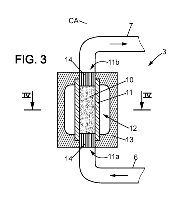
The cell 3 will now be more precisely described in
view of the figure 3 and 4.
The cell 3 has an elongated and generally
cylindrical shape according to the cell axis CA. It
comprises a first cavity comprising the cell axis CA, said
fist cavity being filled up with the rock sample 10 (porous
medium). It basically adopts the mechanical design of a
Hassler type cell, but the nature of the used materials is
different so that it is transparent to X-ray beam to reach
high resolution X-ray tomography.
The cell 3 is made of materials with specific X-ray
properties but working under high pressure and high
temperature conditions (up to the above cited conditions).
Such cell 3 requires higher material thicknesses than for
lower pressures to be able to resist to the stresses. The
present invention is therefore more important when working
with high pressure and high temperature conditions.
The porous medium 10 is surrounded by a sealing
tube 11 having and input port 11a and an output port 11b.
The input and output ports 11a, 11b can be equipped with
diffusers 14 adapted to canalise the fluid in the direction
of the cell axis CA at the input and output of the first
cavity.
The cell 3 also comprises a second cavity 12
CA 02837789 2013-11-29
WO 2012/164091 PCT/EP2012/060440
11
surrounding the sealing tube 11. Said second cavity 12 is
fed with a control fluid that impose pressure and
temperature to said cavity. The sealing tube 11 is for
example made of stainless steel or high performing
polymers. This sealing tube 11 is transmitting the pressure
and temperature from the control fluid to the sample 10
inside the first cavity.
The cell 3 then comprises an outer casing 13 that
surrounds the second cavity 12 and closes its ends in the
longitudinal cell axis direction. This outer casing 13 must
withstand the pressure and temperature conditions imposed
by the control fluid inside the second cavity 12.
The cell casing 13, the control fluid inside the
second cavity 12 and the sealing tube 11 are made of low X-
ray absorbing materials (high level of X-ray transmission
material). Usually, polymeric materials are used in X-ray
tomography devices. But, these polymeric materials cannot
withstand the physical conditions imposed by the control
fluid. In the present invention, the outer casing 13 is
preferably made of beryllium, or beryllium alloy (for
example a beryllium aluminium alloy), or a carbon-carbon
composite. But, other materials may be used if they have an
X-ray transmission higher than 80% and preferably higher
than 90% inside the photon energy bandwidth of 10 keV
to 200 keV.
Thanks to this first feature, the material of the
outer casing 13 has a low effect on the image taken by the
photon detector 4: The 2D acquired images and the 3D
tomography images are less affected by the casing material,
and these images are more contrasted. It is possible to
distinguish elements or fluids inside the sample that have
very close densities, such as water, oil and brine.
The cell casing 13, the control fluid inside the
second cavity 12 and the sealing tube 11 are also
preferably made of a homogeneous material so as the various
images from various cell angles are not affected and not
CA 02837789 2013-11-29
WO 2012/164091 PCT/EP2012/060440
12
noisy because of non homogeneities.
The cell 3 of the present invention is also
preferably positioned inside the photon beam PB according
to the view of figure 4 so as the photon detector 4 is
mainly illuminated via the sample 10. The cell 3 is
positioned near the X-ray source.
The X-ray photon beam PB is crossing the cell 3 and
the transmitted photon beam TPB is projected above the
photon detector 4, said photon detector 4 providing an
image corresponding to said transmitted photon beam PB to
produce an image. The portion of the photon beam PB
crossing the sample 10 is illuminating a central portion 41
of the photon detector, and reciprocally is not
illuminating lateral portions 42 of the photon detector.
Said central portion 41 has a width Ln on the figure 4, and
the photon detector has itself a width L.
The cell 3 is then positioned so as the ratio Ln/L
is higher than 0.7, meaning that at least 70% of the pixels
in the image from the photon detector 4 correspond to
sensitive elements inside the photon detector receiving
transmitted photons that have crossed the sample 10.
Thanks to this second feature, the image of the
sample is more accurate.
The photon detector 4 is composed of a matrix of
sensitive elements that are counting receiving photons
(each X-ray photon is usually converted into an electron
via a scintillator element).
These sensitive elements may have an anti-blooming
functionality: Each of them deliver a pixel value that is
saturated to a maximum value if the counted number of
photon is higher than a maximum limit.
The photon detector 4 is overexposed: It is exposed
to the transmitted photon beam TPB during an exposure
length of time higher than a first time limit. The first
time limit is determined so as the sensitive elements
receiving photons that have not crossed the sample 10 have
CA 02837789 2013-11-29
WO 2012/164091 PCT/EP2012/060440
13
reached said maximum value (blooming saturation)
corresponding to 100% transmission.
The photon detector 4 is not too much overexposed:
The exposure length of time is lower than a second time
limit more realistically a few tenths of seconds. The
second time limit is determined so as the sensitive
elements receiving photons that have crossed the sample 10
have not reached said maximum value (blooming saturation).
Thanks to this third feature, the acquired image is
weakly overexposed and it cancels the informations in the
acquired image corresponding to the cell casing 13, the
control fluid inside the second cavity 12 and the sealing
tube 11 that are not relevant.
The optical station is fitted around the region of
interest to avoid a strong blooming due to direct X-ray
exposure or to the highest thickness of the cell 3 which is
the thicker and therefore the most attenuating zone.
These elements have therefore low effect on the
acquired image provided by the photon detector 4: the
acquired image is again more contrasted.
Contrary to what was expected, the inventors have
discovered that the second and third features (reduced
field of view and over exposition of acquired image) are
not disturbing the following reconstruction computations
for calculating the 3D tomography image.
The prior art X-ray tomography devices are usually
acquiring a complete field of view and acquiring non
overexposed images to compute a 3D tomography image. It is
expected reconstruction problems if it is not done in that
manner.
One benefit of present invention is to optimize the
use of the photon detector 4 to useful region of interest.
The whole pixels of the photon detector are used in the
useful area.
However, in the case of geological or petrophysical
porous sample analysis it was found that these known and
CA 02837789 2013-11-29
WO 2012/164091 PCT/EP2012/060440
14
usual uses of an X-ray tomography device are not relevant.
Thanks to this property, there are significant
progresses in acquisition time which is quite decisive to
image a multiphase flow but also in the reconstruction and
image treatment processes. Considering the outer diameter
of the region of interest (the sample 10) and the outer
diameter of the cell 3, the benefit in acquisition time is
given by the ratio of the integer number of necessary
stitching steps to acquire the whole outer diameter of the
cell 3 divided by the integer number of necessary stitching
steps to acquire the whole outer diameter of the sample 10.
Then, the size of the data set changes with a law
of this square number. This is a great improvement for
reducing the time spent to compute the 3D tomography image.