Language selection

Search

Patent 2838078 Summary

Third-party information liability

Some of the information on this Web page has been provided by external sources. The Government of Canada is not responsible for the accuracy, reliability or currency of the information supplied by external sources. Users wishing to rely upon this information should consult directly with the source of the information. Content provided by external sources is not subject to official languages, privacy and accessibility requirements.

Claims and Abstract availability

Any discrepancies in the text and image of the Claims and Abstract are due to differing posting times. Text of the Claims and Abstract are posted:

  • At the time the application is open to public inspection;
  • At the time of issue of the patent (grant).
(12) Patent: (11) CA 2838078
(54) English Title: PLASTIC-PACKAGE MOTOR
(54) French Title: MOTEUR A EMBALLAGE DE PLASTIQUE
Status: Granted
Bibliographic Data
(51) International Patent Classification (IPC):
  • H02K 5/02 (2006.01)
  • H02K 5/16 (2006.01)
  • H02K 15/14 (2006.01)
(72) Inventors :
  • HUANG, TINGSHUAI (China)
  • JIN, JIANWEI (China)
(73) Owners :
  • ZHONGSHAN BROAD-OCEAN MOTOR MANUFACTURING CO., LTD. (China)
(71) Applicants :
  • ZHONGSHAN BROAD-OCEAN MOTOR MANUFACTURING CO., LTD. (China)
(74) Agent:
(74) Associate agent:
(45) Issued: 2019-02-19
(22) Filed Date: 2013-12-18
(41) Open to Public Inspection: 2014-06-28
Examination requested: 2016-12-19
Availability of licence: N/A
(25) Language of filing: English

Patent Cooperation Treaty (PCT): No

(30) Application Priority Data:
Application No. Country/Territory Date
201220741197.0 China 2012-12-28

Abstracts

English Abstract

A plastic-package motor, including: a rotating shaft, a rotor assembly, a plastic-package stator, a front end cover, a rear end cover, an injection-molding end plate, and a conducting strip. The rotating shaft and the rotor assembly are installed and connected together. The plastic-package stator is sleeved outside the rotor assembly. The front end cover is injection-molded on the injection-molding end plate at the bottom of the plastic-package stator. The injection-molding end plate is covered outside the front end cover. The rear end cover is installed at the other end of the plastic-package stator, and two ends of the rotating shaft are supported on a bearing of the front end cover and a bearing of the rear end cover, respectively. One end of the conducting strip is electrically connected with the front end cover.


French Abstract

Un moteur à emballage de plastique comprend un arbre rotatif, un ensemble de rotor, un stator à emballage de plastique, un couvercle dextrémité avant, un couvercle dextrémité arrière, une plaque dextrémité de moulage par injection et une bande conductrice. Larbre rotatif et lensemble de rotor sont installés et connectés ensemble. Le stator à emballage de plastique est emmanché sur lextérieur de lensemble de rotor. Le couvercle dextrémité avant est moulé par injection sur la plaque dextrémité de moulage par injection au bas du stator à emballage de plastique. La plaque dextrémité de moulage par injection est couverte à lextérieur du couvercle dextrémité avant. Le couvercle dextrémité arrière est installé à lautre extrémité du stator à emballage de plastique et les deux extrémités de larbre rotatif sont supportées sur un palier du couvercle dextrémité avant et un palier du couvercle dextrémité arrière, respectivement. Une extrémité de la bande conductrice est connectée électriquement au couvercle dextrémité avant.

Claims

Note: Claims are shown in the official language in which they were submitted.

CLAIMS
1. A plastic-package motor, comprising:
a) a rotating shaft (1);
b) a rotor assembly (2);
c) a plastic-package stator (3) comprising a first end and a second end;
d) a front end cover (4);
e) a rear end cover (5);
t) an injection-molding end plate (6);
g) a conducting strip (7) comprising a first end and a second end; and
h) a T-shaped pressing block (8) comprising a flange part and a web
part;
wherein:
the rotating shaft (1) and the rotor assembly (2) are installed and
connected together;
the plastic-package stator (3) is sleeved outside the rotor assembly (2);
the front end cover (4) is injection-molded in the injection-molding end
plate (6) at the first end of the plastic-package stator (3);
the injection-molding end plate (6) is covered outside the front end
cover (4);
the rear end cover (5) is installed at the second end of the plastic-
package stator (3), and two ends of the rotating shaft (1) are supported on a
bearing (41) of the front end cover (4) and a bearing (51) of the rear end
cover
(5) respectively;
a groove (61) is formed outside the front end cover (4) and on an end
surface of the injection-molding end plate (6);
8

the first end of the conducting strip (7) is embedded in the groove (61)
and is in contact with and electrically connected with the front end cover
(4);
the web part of the T-shaped pressing block (8) is embedded in the
groove (61) and abuts against the first end of the conducting strip (7);
the flange part of the T-shaped pressing block (8) is disposed outside of
the groove and abuts against the injection-molding end plate (6);
the second end of the conducting strip (7) is supported on an end
surface of the second end of the plastic-package stator (3) and is pressed by
and electrically connected with the rear end cover (5).
2. The motor of claim 1, wherein a notch (31) is formed at the end surface
of the
second end of the plastic-package stator (3), and the conducting strip (7) is
embedded in the notch (31).
3. The motor of claim 1, wherein a strip-shaped groove (32) is formed on a
wall
surface on an outer side of the plastic-package stator (3), extends onto an
end
surface of the front end cover (4) and is communicated with the groove (61),
and the conducting strip (7) is embedded in the strip-shaped groove (32).
4. The motor of claim 1, wherein the T-shaped pressing block (8) is a rivet
or a
screw.
5. The motor of claim 1, wherein a circuit board (9) is supported and
installed on
a step (33) in the plastic-package stator (3).
6. The motor of claim 1, wherein both the front end cover (4) and the rear
end
cover (5) are made of conductive metal material.
7. The motor of claim 1, wherein the conducting strip (7) is made of
conductive
material.
9

8. The motor of claim 7,
wherein the conducting strip (7) is a copper sheet or
conductive lead wire.

Description

Note: Descriptions are shown in the official language in which they were submitted.


CA 02838078 2013-12-18
PLASTIC-PACKAGE MOTOR
FIELD OF THE INVENTION
[0001] The invention relates to a plastic-package motor.
BACKGROUND OF THE INVENTION
[0002] In the plastic-package DC brushless motor, as the plastic packaging
material of
the motor body part is insulated, actually, the front end cover cannot be
directly
conducted with the rear end cover, and the motor structure cannot prevent the
electrical
erosion of a bearing. Thus, the lubricating oil for the bearing causes
insulation destruction
to generate shaft current, wavy wear is found in the inner ring and the outer
ring of the
bearing, and abnormal sound occurs. Therefore, so as to solve the problems, a
conductive
adhesive tape is usually stuck on the outer surface of the motor or an
electric conductor is
connected, however, the plastic-package motor is easy to fall off during the
transportation,
and has poor reliability.
SUMMARY OF THE INVENTION
[0003] In view of the above-described problems, it is one objective of the
invention to
provide a plastic-package motor. The plastic-package motor has a simple
structure, solves
the problem of electrical erosion of a bearing, and is thin in connection and
good in
reliability.
[0004] The objective is achieved according to the following technical schemes.

[0005] A plastic-package motor comprises: a rotating shaft, a rotor assembly,
a
1

CA 02838078 2013-12-18
plastic-package stator, a front end cover, a rear end cover, an injection-
molding end plate,
and a conducting strip. The rotating shaft and the rotor assembly are
installed and =
connected together. The plastic-package stator is sleeved outside the rotor
assembly. The
front end cover is injection-molded on the injection-molding end plate at a
bottom of the
plastic-package stator. The injection-molding end plate is covered outside the
front end
cover. The rear end cover is installed at the other end of the plastic-package
stator, and
two ends of the rotating shaft are supported on a bearing of the front end
cover and a
bearing of the rear end cover respectively. One end of the conducting strip is
electrically
connected with the front end cover, and the other end of the conducting strip
is supported
on an end surface of the plastic-package stator and is pressed by and
electrically
connected with the rear end cover.
[0006] In a class of this embodiment, a groove is formed outside the front end
cover and
on an end surface of the injection-molding end plate. The conducting strip is
embedded in
the groove and electrically connected with the front end cover, and a pressing
block is
embedded in the groove and presses on the conducting strip.
(0007] In a class of this embodiment, a notch is formed at the end surface of
the other end
of the plastic-package stator, and the conducting strip is embedded in, the
notch.
[000S] In a class of this embodiment, a strip-shaped groove is formed on a
wall surface
on an outer side of the plastic-package stator, extends onto an end surface of
the front end
cover and is communicated with the groove, and the conducting snip is embedded
in the
strip-shaped groove.
[00091 In a class of this embodiment, the pressing block is a rivet or a
screw.
[0010] In a class of this embodiment, a circuit board is supported and
installed on a step
in the plastic-package stator.
2

CA 02838078 2013-12-18
[0011] In a class of this embodiment, both the front end cover and the rear
end cover are
made of conductive metal material.
[0012] In a class of this embodiment, the conducting strip is made of
conductive material.
[0013] In a class of this embodiment, the conducting strip is a copper sheet
or conductive
lead wire.
[0014] Advantages of the invention are summarized below:
[0015] (1) the conducting strip is additionally arranged, one end of the
conducting
strip is electrically connected with the front end cover, and the other end of
the
conducting strip is supported on the end surface of the plastic-package stator
and
is electrically connected with the rear end cover through being pressed by the
rear
end cover, thus the plastic-package motor has a simple structure, solves the
problem of electrical erosion of a bearing, and is firm in connection and good
in
reliability;
[0016] (2) the groove is formed outside the front end cover and on the end
surface
of the injection-molding end plate, the conducting strip is embedded in the
groove
and electrically connected with the front end cover, the pressing block is
embedded in the groove and pressed on the conducting strip and adopts a rivet
or
screw, thus the structural design is reasonable, the installation is easy, and
due to
the use of a riveting tool, the assembly is simpler, and the process is
better;
[0017] (3) the notch is formed at the end part of the other end of the
plastic-package stator, the conducting strip is embedded in the notch and
positioned through the notch, installation can be carried out in one step,
thus the
extra production process is avoided, the efficiency is improved, and the labor

cost is saved;
3

CA 02838078 2013-12-18
[0018] (4) the strip-shaped groove is formed on the wall surface on the outer
side
of the plastic-package stator, extends onto the end surface of the front end
cover
and is communicated with the groove, the conducting strip is embedded in the
strip-shaped groove, and the strip-shaped groove is directly reserved on the
plastic-package stator mold, thus not only the dimensional accuracy is good,
but
also the front end cover is not required to be positioned during the
production of
the plastic-package stator, and the production assembly is simple.
BRIEF DESCRIPTION OF THE DRAWINGS
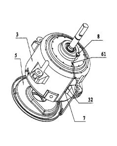
[0019] FIG. 1 is a stereograph of a plastic-package motor of the invention;
[0020] FIG. 2 is an exploded view of a plastic-package motor of the invention;

[0021] FIG. 3 is another exploded view of a plastic-package motor of the
invention;
[0022] FIG. 4 is a schematic diagram of a plastic-package motor of the
invention;
[0023] FIG. 5 is an exploded view of FIG. 4 taken from line A-A;
[0024] FIG 6 is an enlarged view of part B-B of FIG 5; and
[0025] FIG. 7 is an enlarged view of part C-C of FIG; 5.
DETAILED DESCRIPTION OF THE EMBODIMENTS
Example 1
[0026] As shown in FIG. 1 to FIG. 7, a plastic-package motor comprises a
rotating shaft 1,
4

CA 02838078 2013-12-18
a rotor assembly 2, a plastic-package stator 3, a front end covet 4 and a rear
end cover 5.
The rotating shaft 1 and the rotor assembly 2 are installed and connected
together. The
plastic-package stator 3 is sleeved outside the rotor assembly 2. The front
end cover 4 is
injection-molded on an injection-molding end plate 6 at the bottom of the
plastic-package
stator 3. The injection-molding end plate 6 is covered outside the front end
cover 4. The
rear end cover 5 is installed at the other end of the plastic-package stator
3, and two ends
of the rotating shaft 1 are supported on a bearing 41 of the front end cover 4
and a bearing
51 of the rear end cover 5 respectively. The plastic-package motor further
comprises a
conducting strip 7. One end of the conducting strip 7 is electrically
connected with the
front end cover 4, and the other end of the conducting strip 7 is supported on
the end
surface of the plastic-package stator 3 and is electrically connected with the
rear end
cover 5 through being pressed by the rear end cover 5.
Example 2
[0027] On the basis of Example 1, the technical characteristics are added as
follows: a
groove 61 is formed outside the front end cover 4 and on the end surface of
the
injection-molding end plate 6, the conducting strip 7 is embedded in the
groove 61 and
electrically connected with the front end cover 4, and a pressing block 8 is
embedded in
the groove 61 and pressed on the conducting strip 7.
Example 3
[0028] On the basis of Example 1 or 2, the technical characteristics are added
as follows:
a notch 31 is formed at the end part of the other end of the plastic-package
stator 3, and
the conducting strip 7 is embedded in the notch 31.

CA 02838078 2013-12-18
Example 4
[0029] On the basis of Example 2, the technical characteristics are added as
follows: a
strip-shaped groove 32 is formed on the wall surface on the outer side of the
plastic-package stator 3, extends onto the end surface of the front end cover
4 and is
communicated with the groove 61, and the conducting strip 7 is embedded in the

strip-shaped groove 32.
Example 5
[0030] On the basis of Example 2, the technical characteristics are added as
follows: the
pressing block 8 is a rivet or a screw.
Example 6
[0031] On the basis of Example 1, the technical characteristic is added as
follows: a
circuit board 9 is supported and installed on a step 33 in the plastic-package
stator 3.
Example 7
10032] On the basis of Example 1, the technical characteristic is added as
follows: both
the front end cover 4 and the real end cover 5 are made of conductive metal
material.
Example 8
6

CA 02838078 2013-12-18
[0033] On the basis of Example 1, the technical characteristic is added as
follows: the
conducting strip 7 is made of conductive material.
Example 9
[0034] On the basis of Example 8, the technical characteristic is added as
follows: the
conducting strip 7 is a copper sheet or conductive lead wire,
[0035] While particular embodiments of the invention have been shown and
described, it
will be obvious to those skilled in the art that changes and modifications may
be made
without departing from the invention in its broader aspects, and therefore,
the aim in the
appended claims is to cover all such changes and modifications as fan within
the true
spirit and scope of the invention,
[0036] The conducting strip 7 is additionally arranged, one end of the
conducting strip 7
is electrically connected with the front end cover 4, and the other end of the
conducting
strip 7 is supported on the end surface of the plastic-package stator 3 and is
electrically
connected with the rear end cover 5 through being pressed by the rear end
cover 5.
Therefore, the plastic-package motor has a simple structure, solves the
problem of
electrical erosion of a bearing, and is firm in connection and good in
reliability.
7

Representative Drawing
A single figure which represents the drawing illustrating the invention.
Administrative Status

For a clearer understanding of the status of the application/patent presented on this page, the site Disclaimer , as well as the definitions for Patent , Administrative Status , Maintenance Fee  and Payment History  should be consulted.

Administrative Status

Title Date
Forecasted Issue Date 2019-02-19
(22) Filed 2013-12-18
(41) Open to Public Inspection 2014-06-28
Examination Requested 2016-12-19
(45) Issued 2019-02-19

Abandonment History

There is no abandonment history.

Maintenance Fee

Last Payment of $263.14 was received on 2023-10-26


 Upcoming maintenance fee amounts

Description Date Amount
Next Payment if standard fee 2024-12-18 $347.00
Next Payment if small entity fee 2024-12-18 $125.00

Note : If the full payment has not been received on or before the date indicated, a further fee may be required which may be one of the following

  • the reinstatement fee;
  • the late payment fee; or
  • additional fee to reverse deemed expiry.

Patent fees are adjusted on the 1st of January every year. The amounts above are the current amounts if received by December 31 of the current year.
Please refer to the CIPO Patent Fees web page to see all current fee amounts.

Payment History

Fee Type Anniversary Year Due Date Amount Paid Paid Date
Application Fee $400.00 2013-12-18
Maintenance Fee - Application - New Act 2 2015-12-18 $100.00 2015-12-10
Request for Examination $800.00 2016-12-19
Maintenance Fee - Application - New Act 3 2016-12-19 $100.00 2016-12-19
Maintenance Fee - Application - New Act 4 2017-12-18 $100.00 2017-12-18
Maintenance Fee - Application - New Act 5 2018-12-18 $200.00 2018-11-08
Final Fee $300.00 2018-12-27
Maintenance Fee - Patent - New Act 6 2019-12-18 $200.00 2019-12-02
Maintenance Fee - Patent - New Act 7 2020-12-18 $200.00 2020-08-11
Maintenance Fee - Patent - New Act 8 2021-12-20 $204.00 2021-10-25
Maintenance Fee - Patent - New Act 9 2022-12-19 $203.59 2022-07-18
Maintenance Fee - Patent - New Act 10 2023-12-18 $263.14 2023-10-26
Owners on Record

Note: Records showing the ownership history in alphabetical order.

Current Owners on Record
ZHONGSHAN BROAD-OCEAN MOTOR MANUFACTURING CO., LTD.
Past Owners on Record
None
Past Owners that do not appear in the "Owners on Record" listing will appear in other documentation within the application.
Documents

To view selected files, please enter reCAPTCHA code :


To view images, click a link in the Document Description column. To download the documents, select one or more checkboxes in the first column and then click the "Download Selected in PDF format (Zip Archive)" or the "Download Selected as Single PDF" button.

List of published and non-published patent-specific documents on the CPD .

If you have any difficulty accessing content, you can call the Client Service Centre at 1-866-997-1936 or send them an e-mail at CIPO Client Service Centre.


Document
Description 
Date
(yyyy-mm-dd) 
Number of pages   Size of Image (KB) 
Maintenance Fee Payment 2019-12-02 2 52
Maintenance Fee Payment 2021-09-16 1 34
Maintenance Fee Payment 2021-09-14 1 156
Maintenance Fee Payment 2021-10-25 1 154
Abstract 2013-12-18 1 19
Description 2013-12-18 7 223
Claims 2013-12-18 3 58
Drawings 2013-12-18 7 129
Representative Drawing 2014-06-03 1 15
Cover Page 2014-07-23 1 48
Examiner Requisition 2017-10-04 3 198
Maintenance Fee Payment 2017-12-18 2 54
Amendment 2018-03-20 13 340
Claims 2018-03-20 3 64
Maintenance Fee Payment 2018-11-08 2 53
Final Fee 2018-12-27 2 48
Representative Drawing 2019-01-21 1 12
Cover Page 2019-01-21 1 43
Assignment 2013-12-18 4 127
Maintenance Fee Payment 2015-12-10 2 59
Maintenance Fee Payment 2016-12-19 1 37
Fees 2016-12-19 2 65