Note: Descriptions are shown in the official language in which they were submitted.
CA 02838390 2013-12-30
PRESSURE ADJUSTMENT APPARATUS
TECHNICAL FIELD
The present disclosure relates to the field of industrial control, and in
particular to a
pressure adjustment apparatus using a double closed-loop PI control method to
control
a conventional rough pressure adjusting mechanism and the change of the
chamber
volume of a pressure-withstanding container of a material with a high thermal
expansion coefficient to work in cooperation, so as to achieve precise
adjustment of
pressure.
BACKGROUND
Pressure measurement plays an important role in the industrial process
control. The
performance of a pressure calibrating apparatus decides the calibration
precision,
efficiency and cost of a pressure instrument. Fully automatic pressure
calibrators are
replacing conventional piston pressure gauges gradually, and are widely
applied in the
field of electrical power, petroleum, petrochemical engineering, metallurgy,
pharmacy or
the like for it has many advantages such as high precision, wide application
area, easy
operation, functional integration, small size and so on.
Fully automatic pressure calibrators can be classified into gas pressure
calibrators and
liquid pressure calibrators depending on different instruments to be
calibrated. The gas
pressure calibrator takes non-corrosive gas as working medium, and is usually
used to
calibrate pressure instruments with relatively small measure range. Normal gas
pressure calibrators control the gas input quantity and the gas output
quantity of the
pressure-making chamber by using the ON/OFF of an electromagnetic valve to
thus
achieve the purpose of adjusting pressure, as shown in Fig. 1C. The liquid
pressure
calibrator takes non-conductive liquid such as transformer oil, sebacate,
deionized
water and so on as working medium, and is usually used to calibrate pressure
1
CA 02838390 2013-12-30
instruments with relatively large measure range. Normal liquid pressure
calibrators
change the volume of the working medium in the cylinder by using an electric
motor or
gas to push the piston to move in the cylinder, thus achieving the purpose of
adjusting
pressure, as shown in Fig. 1A and Fig. 1B.
Currently, the pressure-making precision of a fully automatic pressure
calibrator is
mainly subject to the performance of the pressure sensor and the actuating
mechanism.
The performance of the actuating mechanism is determined by the fabrication
precision,
the consistency of elements and the cost of fabrication and purchase of the
actuating
mechanism.
In a conventional gas pressure system, the response time of the
electromagnetic valve
is usually in the range of 10-30 ms, or in the range of 5-10 ms for better
ones.
Moreover, its price is very high, and the consistency cannot be assured. The
amount of
gas flow during the smallest switching interval of the electromagnetic valve
usually
decides the precision of the pressure adjustment. Reducing the amount of gas
flow
during the smallest switching interval by reducing the pressure difference
between the
two sides of the electromagnetic valve would usually increase the complexity
of the
system and improve the cost. Though reducing the path diameter of
the
electromagnetic valve can reduce the amount of gas flow during the smallest
switching
interval, it increases the adjustment time at the same time. Increasing the
volume of
the pressure-making chamber would increase the vibration of the gas due to the
bulk-
cavity effect and would thus increase the adjustment time. In a conventional
liquid
pressure system, for a pressure-making system by the electric motor pushing
the
piston, the fabrication precision of the transmission screw would influence
the shift of
the piston in a unit step of the electric motor, and thus influence the
resolution of the
pressure adjustment. High precision screws are usually very expensive, and not
easy
to be fabricated. The electric motor adapted thereto also needs to be a
stepper motor
or a servo motor with high precision, stable torque, and low heating, which
further
2
CA 02838390 2013-12-30
. .
improves the cost of the system. For a pressure-making system with gas pushing
liquid, the same difficulties as the gas pressure system exist.
SUMMARY OF THE DISCLOSURE
In view of the above, the technical problems to be solved by the present
disclosure is to
overcome the disadvantages of the prior art, and provide a control system in
which
precise pressure adjustment is performed with the deformation of a pressure-
withstanding container of a material with high thermal expansion coefficients
such as
aluminum, copper, iron, and so on in cooperation with a conventional rough
pressure
adjusting mechanism (e.g., a liquid pressure cylinder or a gas actuating
electromagnetic valve ). A double closed-loop PI control method is used, so as
to
reduce the performance requirement on a conventional adjusting mechanism,
simplify
the system structure, reduce the influence of the element cost and consistency
of the
system, and improve the precision of the pressure-making to some extent.
In order to achieve the above object, one aspect of the present disclosure
provides a
pressure adjustment apparatus, comprising: an actuating mechanism (1)
comprising a
temperature sensing chamber (3), a temperature control apparatus (4), a rough
pressure adjusting mechanism (5) and a pressure-making chamber (10), the
pressure-
making chamber (10) being connected to the chamber of the temperature sensing
chamber (3) to make the pressure within the chambers equal; and a control
mechanism
(2) comprising a processor (6), a touch screen (7), an analog-to-digital
converter (8)
and a pressure sensor (9), wherein the pressure sensor (9) senses the pressure
within
the pressure-making chamber (10) and outputs an electric signal which is
computed by
the processor (6) to obtain a realtime pressure value after being collected by
the
analog-to-digital converter (8), and the processor (6) compares a set pressure
value
inputted by a user though the touch screen (7) with the current pressure value
to obtain
an error value, and performs a double closed-loop control on the actuating
mechanism
3
CA 02838390 2013-12-30
(1) to adjust the pressure within the pressure-making chamber (10) by
comparing the
error value with a set error threshold.
In accordance with the pressure adjustment apparatus in a preferable
embodiment of
the present disclosure, the double closed-loop control further comprises:
when the error value is outside the set error threshold range, the processor
(6) initiating
an inner loop to control the rough pressure adjusting mechanism (5) to perform
rough
pressure adjustment rapidly; when the error value is within the set error
threshold range,
the processor (6) initiating an outer loop to control the temperature control
apparatus (4)
to change the temperature of the temperature sensing chamber (3) and thus to
change
the chamber volume of the temperature sensing chamber (3).
In accordance with the pressure adjustment apparatus in a preferable
embodiment of
the present disclosure, the temperature sensing chamber is a pressure-
withstanding
container made of aluminum, copper or iron with a high thermal expansion
coefficient.
In accordance with the pressure adjustment apparatus in a preferable
embodiment of
the present disclosure, the temperature control apparatus is composed of a
power
resistor, a Pt thermocouple, a heat dissipater and a power supply
In accordance with the pressure adjustment apparatus in a preferable
embodiment of
the present disclosure, the analog-to-digital converter (8) is a y -A typed
analog-to-
digital converter (8).
Compared with the prior art, the present disclosure has the following
advantages due to
the adoption of the above features.
(1) In the present disclosure, an inner-loop conventional pressure adjusting
mechanism
and an outer-loop temperature control apparatus are used to cooperate with
each
other. A stable pressure adjustment with high precision is achieved by
changing the
4
CA 02838390 2013-12-30
. .
temperature and thus the volume of the temperature sensing chamber. The
present
disclosure can be applied to both the gas pressure system and the liquid
pressure
system.
(2) The present disclosure adopts a double closed-loop PI control method to
make the
rough pressure adjusting mechanism and the temperature control apparatus
cooperate with each other so as to reach a stable set pressure rapidly. That
is,
when the error value is outside the set error threshold range, the rough
pressure
adjusting mechanism is initiated to rapidly adjust the pressure; when the
error value
is within the set error threshold range, the temperature control apparatus is
initiated
to adjust the pressure precisely. In both inner and outer PI components, when
the
error value is outside respective set error threshold ranges, the adjustment
mechanism adjusts the pressure with the highest adjustment speed; and once the
error value falls into the set error threshold range, a parameter self-
regulating PI
control method is used to adjust the pressure. In order to improve the
performance
of the closed-loop control system, shorten the response time, and make the
pressure-making system to reach the stable set pressure as soon as possible,
in
both inner and outer loops, the coefficients of respective components of the
PI
controller are regulated appropriately according to the error value. Compared
with
the ordinary PI control method, it shortens the response time dramatically and
improves the capability of disturbance resistance.
(3) The structure according to the present disclosure is simple, and the
operation of the
temperature control apparatus and the temperature sensing chamber is simple.
The conventional pressure adjustment mechanism adapted thereto needs
relatively
low fabrication precision and consistency. The cost is also reduced, and there
is a
promising potential market.
BRIEF DESCRIPTION OF THE DRAWINGS
Fig. 1A is a schematic diagram of a liquid pressure adjusting mechanism with
an
electric motor pushing a piston.
5
CA 02838390 2013-12-30
. .
Fig. 1B is a schematic diagram of a liquid pressure adjusting mechanism with
gas
pushing a piston.
Fig. 1C is a diagram of a gas pressure adjusting mechanism with an
electromagnetic valve controlling the gas input quantity and the gas output
quantity.
Fig. 2 is a structural block diagram of a pressure adjustment apparatus
provided in
an embodiment of the present disclosure.
Fig. 3 is a schematic diagram of a temperature sensing chamber and a
temperature control apparatus of the present disclosure.
Fig. 4 is a flowchart of the processor implementation in the present
disclosure.
Fig. 5 is a structural diagram the parameter self-regulating PI control.
DETAILED DESCRIPTION
In the following, the technical solutions of the present disclosure will be
further
described in detail in connection with drawings and embodiments.
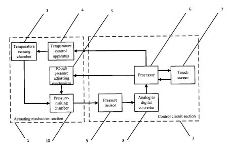
As shown in Fig. 2, embodiments of the present disclosure provide a pressure
adjustment apparatus which performs precise pressure adjustment with
temperature
control. The apparatus comprises an actuating mechanism 1 and a control
mechanism
2. The actuating mechanism 1 comprises a temperature sensing chamber 3, a
temperature control apparatus 4, a rough pressure adjusting mechanism 5 and a
pressure-making chamber 10, the pressure-making chamber 10 being connected to
the
chamber of the temperature sensing chamber 3 to make the pressure within the
chambers equal. The control mechanism 2 comprises a processor 6, a touch
screen 7,
an analog-to-digital converter 8 and a pressure sensor 9. The control
mechanism
composed of the pressure sensor 9, the analog to digital converter 8, and the
processor 6 is also referred to as a control circuit. With the double closed-
loop PI
control method, the control mechanism can control the rough pressure adjusting
mechanism 5 and the change in the chamber volume of the temperature sensing
6
CA 02838390 2013-12-30
chamber 3 controlled by the temperature apparatus 4 to make them cooperate
with
each other to achieve a stable and fast pressure adjustment.
As shown in Fig. 3, the temperature sensing chamber of the present disclosure
can
adopt a common pressure-withstanding container made of aluminum, copper or
iron
with a high thermal expansion coefficient. The temperature control apparatus
is simple
in principle, and can usually be composed of a power resistor, a Pt
thermocouple, a
heat dissipater and a power supply. The processor controls the temperature of
the
temperature sensing chamber and then changes the chamber volume thereof
through
the temperature control apparatus. When the pressure needs to be raised, the
voltage
modulation duty cycle on the power resistor of the temperature control
apparatus is
reduced to reduce the temperature of the power resistor. The surface area of
the heat
dissipater can be chosen to be larger, and if necessary, a heat dissipating
fan can be
additionally provided to reduce the temperature of the temperature sensing
chamber
accordingly. Then the chamber volume of the temperature sensing chamber
decreases when the temperature decreases. When the pressure needs to be
reduced,
the voltage modulation duty cycle on the power resistor of the temperature
control
apparatus is raised to increase the temperature of the power resistor. If a
heat
dissipating fan is additionally provided, it should be turned off to make the
temperature
of the temperature sensing chamber increase accordingly. Then the chamber
volume
of the temperature sensing chamber increases when the temperature increases.
Since
the temperature sensing chamber is connected to the pressure-making chamber,
there
is an equal pressure within their chambers. The chamber volume of the
temperature
sensing chamber should be suitable for the total volume of the entire pressure-
making
circuit. If it is too small, the pressure adjusting range would be small. If
it is too large, it
cannot function for precise pressure adjustment. At the same time, the
pressure
adjusting resolution of the rough pressure adjusting mechanism also needs to
be
considered.
7
CA 02838390 2013-12-30
. .
As shown in Fig. 4, the processor 6 in the present disclosure receives a set
pressure
value set by a user through the touch screen 7. The pressure sensor 9 senses
the
pressure value within the pressure-making chamber 10. The pressure value is
collected by the analog-to-digital converter 8 and then computed by the
processor 6 to
obtain the current pressure value. The processor 6 compares the set pressure
value
with the current pressure value to obtain an error value. When the error value
is
outside the set error threshold range, the processor 6 initiates the rough
pressure
adjusting mechanism 5 of the inner loop through a parameter self-regulating PI
control
method to adjust the pressure rapidly while the temperature control apparatus
4 of the
outer loop does not work. When the error value is within the set error
threshold range,
the processor 6 initiates the temperature control apparatus 4 of the outer
loop to
perform precise pressure adjustment through a parameter self-regulating PI
control
method while the rough pressure adjusting mechanism 5 of the inner loop does
not
work. The above closed-loop control method is performed cyclically until the
stable set
pressure is achieved.
As shown in Fig. 5, in the embodiments of the present disclosure, the
processor 6
controls the pressure through a double closed-loop parameter self-regulating
PI control
method. The processor adjusts the proportion coefficient Kp and the
integration
coefficient Ki of the PI component according to the error value through the PI
control
algorithm. The output of Kp control is proportional to the input error value
and is used
for fast response. The output of Ki control is proportional to the integral of
the error
value, and is used to eliminate the static error. That is, when the absolute
error value is
relatively large (in the present embodiment, larger than 20% of the input
value of the
inner or outer loop), Kp takes a relatively large value (in the present
embodiment, 30),
Ki takes 0, and at this point the rough pressure adjusting mechanism 5 or the
temperature sensing chamber 3 adjusts the pressure rapidly or increases or
decreases
temperature rapidly to make the absolute error value decrease as soon as
possible.
When the absolute error value is medium (in the present embodiment, larger
than 10%
and smaller than 20% of the input value of the inner or outer loop), Kp takes
a medium
8
CA 02838390 2013-12-30
value (in the present embodiment, 25), Ki takes a relatively small value (in
the present
embodiment, 0.0005), and at this point the rough pressure adjusting mechanism
5 or
temperature sensing chamber 3 reduces the speed of adjusting the pressure or
increasing or decreasing temperature to avoid over-adjusting. When the
absolute error
value decreases further (in the present embodiment, larger than 5% and smaller
than
10% of the input value of the inner or outer loop), Kp takes a relatively
small value (in
the present embodiment, 5), Ki takes a medium value (in the present
embodiment,
0.02), and at this point, the rough pressure adjusting mechanism 5 or the
temperature
of the temperature sensing chamber 3 is adjusted slowly. When the absolute
error
value reaches the smallest (in the present embodiment, smaller than 5% of the
input
value of the inner loop), Kp takes a medium value (in the present embodiment,
20), Ki
takes the maximum value (in the present embodiment, 0.02), and at this point,
mainly
the temperature of the temperature sensing chamber 3 is adjusted finely to
achieve the
function of precise pressure adjustment. The above process makes both the
inner and
outer loops respond rapidly so that the closed-loop system can reach the
stable set
pressure faster. The method responds faster than the conventional PI control
method.
The pressure sensor 9 can adopt commonly used silicon piezoresistive pressure
sensors or silicon resonant pressure sensors, depending on the requirement of
precision and performance.
Considering that the electric signal output by the pressure sensor 9 usually
is a weak
signal in the level of uA or mV, and the pressure signal within the pressure-
making
chamber 10 cannot change rapidly within a short time, it is proposed to use a
high
resolution, high signal-to-noise ratio, high integration I-A typed analog-to-
digital
converter 8, for example, AD7714.
The processor 6 can be implemented by commonly used digital signal processors,
ARM or the like, for example, TMS320F28335 or the like.
9
CA 02838390 2013-12-30
=
The set pressure input by a user can be implemented by a touch screen or a
simple
button or digital tube.
The principle of the present disclosure is as follows. A conventional rough
pressure
adjusting mechanism and the change in the chamber volume of a pressure-
withstanding chamber of materials with high thermal expansion coefficients are
used to
cooperate with each other to achieve a high speed and stable pressure-making
function by a double closed-loop PI control method. In the aspect of the
actuating
mechanism, the requirement on the performance of the conventional rough
pressure
adjusting mechanism is reduced since it is only used for rough pressure
adjustment.
When the error value is within the set error value range, the temperature
control
apparatus is initiated to work in order to change the temperature of the
temperature
sensing chamber and then to change the chamber volume of the temperature
sensing
chamber, whereby the purpose of precise pressure adjustment is achieved. In
the
aspect of software, a double closed-loop PI control method is used in which
the current
pressure value read realtime by the pressure sensor is compared with the user
set
value to obtain an error value. According to the amplitude of the error value,
the
parameters of PI components are self-regulated, reducing the adjustment time
drastically. The rough pressure adjusting mechanism of the inner loop is
controlled first
to rapidly adjust the pressure to fall within the set error threshold range.
Then the
adjustment of the inner loop is stopped, and the temperature control apparatus
of the
outer loop is controlled to rapidly and stably perform precise pressure
adjustment.
The above specific implementation provides a further detailed description of
the object,
the technical solutions and the technical benefits of the present disclosure.
It should be
understood that the above description is only specific embodiments of the
present
disclosure and is not intended to limit the protection scope of the present
disclosure.
Any modification, equivalent replacement, enhancement or the like within the
principle
of the present disclosure should all be contained within the protection scope
of the
present disclosure.