Note: Descriptions are shown in the official language in which they were submitted.
CA 02838847 2013-12-06
WO 2012/170861 PCT/US2012/041623
CONNECTOR HAVING A COUPLING MEMBER FOR LOCKING ONTO A PORT AND
MAINTAINING ELECTRICAL CONTINUITY
FIELD OF TECHNOLOGY
[0001] The following relates to connectors used in coaxial cable
communication
applications, and more specifically to embodiments of a push-on connector
having a coupling
member for maintaining continuity through a connector and retaining the
connector onto a
corresponding port.
BACKGROUND
[0002] Connectors for coaxial cables are typically connected onto
complementary
interface ports to electrically integrate coaxial cables to various electronic
devices. Push-on
connectors are widely used by consumers for their ease of use, and apparent
adequacy, but they
rarely stay properly secured onto the port over time. Even push-on connectors
designed to lock
the connector onto a port can slip off the port if the cable is tugged, and
the range of allowable
port diameters makes it extremely difficult to create sufficient friction
between the push-on
connector and the tops of the external threads of both small and large ports.
By contrast,
connectors involving a threaded coupling member can provide enough retention
force up to the
breaking strength of a coaxial cable; however, threaded coupling members must
also be rotated
onto the port during installation. Furthermore, it is desirable to maintain
continuity through a
coaxial cable connector, which typically involves the continuous contact of
conductive connector
components which can prevent radio frequency (RF) leakage and ensure a stable
ground
connection.
[0003] Thus, a need exists for an apparatus and method for preventing
disengagement of
a push-on connector from a port. A need also exists for a push-on connector
that can lock onto a
port while also ensuring continuous contact between conductive components of a
connector.
SUMMARY
[0004] A first general aspect relates to a coupling member comprising a
body defined by
an inner surface and an outer surface between a first end a second end, at
least one resilient
contact extending a distance from the inner surface of the body, the at least
one resilient contact
configured to provide a retention force, and at least one resilient protrusion
extending a distance
1
CA 02838847 2013-12-06
WO 2012/170861 PCT/US2012/041623
from the inner surface of the body, the at least one resilient positioned
proximate the second end
of the body and configured to contact a conductive surface.
[0005] A second general aspect relates to a coaxial cable connector for
mating with an
interface port having external threads, comprising a post configured to
receive a center conductor
surrounded by a dielectric of a coaxial cable, a connector body attached to
the post, a coupling
member attached to the post, the coupling member having one or more resilient
contacts,
wherein the resilient contacts are configured to pass over the external
threads in a first axial
direction, and physically engage the external threads in a second axial
direction.
[0006] A third general aspect relates to a coaxial cable connector for
connecting to an
interface port comprising a post having configured to receive a prepared end
of a coaxial cable
having a center conductor surrounded by a dielectric, a connector body
attached to the post, a
coupling member attached to the post, the coupling member having a first end
and a second end,
wherein the coupling member includes a first set of contacts proximate the
second end
configured to maintain electrical continuity between the coupling member and
the post, and a
second set of contacts configured to provide a retention force in an axial
direction between the
coupling member and the port.
[0007] A fourth general aspect relates to a coaxial cable connector
adapted to mate with a
port, comprising a post configured to receive a center conductor surrounded by
a dielectric of a
coaxial cable, a connector body attached to the post, a coupling member
operably attached to the
post, the coupling member having a first end and a second end, and a means for
providing a
retention force in an axial direction between the coupling member and the
port, wherein the
means for providing the retention force is integral with the coupling member.
[0008] A fifth general aspect relates to a connector for connecting to an
interface port
comprising a post having configured to receive a prepared end of a coaxial
cable having a center
conductor surrounded by a dielectric, a connector body attached to the post, a
coupling member,
the coupling member having a first end and a second end, wherein the coupling
member includes
a first set of contacts proximate the second end configured to maintain
electrical continuity
through the connector, and a second set of contacts configured to provide a
retention force in an
axial direction between the coupling member and the port.
[0009] A sixth general aspect relates to a method of retaining a
connector onto a port in
an axial direction, comprising providing a post configured to receive a center
conductor
2
CA 02838847 2013-12-06
WO 2012/170861 PCT/US2012/041623
surrounded by a dielectric of a coaxial cable, a connector body attached to
the post, a coupling
member attached to the post, wherein the coupling member has a first and
second end, and
forming one or more resilient contacts on the coupling member, wherein the
resilient contacts are
configured to pass over the external threads in a first axial direction, and
physically engage the
external threads in a second axial direction.
[0010] A seventh general aspect relates to a jumper comprising a first
connector, wherein
the first connector includes a post configured to receive a center conductor
surrounded by a
dielectric of a coaxial cable, a connector body attached to the post, and a
coupling member
attached to the post, the coupling member having one or more resilient
contacts, wherein the
resilient contacts are configured to pass over the external threads in a first
axial direction, and
physically engage the external threads in a second axial direction, and a
second connector,
wherein the first connector is operably affixed to a first end of a coaxial
cable, and the second
connector is operably affixed to a second end of the coaxial cable.
[0011] The foregoing and other features of construction and operation
will be more
readily understood and fully appreciated from the following detailed
disclosure, taken in
conjunction with accompanying drawings.
BRIEF DESCRIPTION OF THE DRAWINGS
[0012] Some of the embodiments will be described in detail, with
reference to the
following figures, wherein like designations denote like members, wherein:
FIG. 1 depicts a perspective view of a first embodiment of a coaxial cable
connector;
FIG. 2 depicts a perspective view of an embodiment of a coaxial cable;
FIG. 3 depicts a cross-sectional view of the embodiment of the connector;
FIG. 4 depicts a perspective view of an embodiment of a coupling member;
FIG. 5 depicts a first cross-sectional view of an embodiment of the coupling
member;
FIG. 6 depicts a second cross-sectional view of an embodiment of the coupling
member;
FIG. 7 depicts a cross-sectional view of an embodiment of a resilient contact
having a tip
engaged with a thread of a port;
FIG. 8 depicts a cross-sectional view of a second embodiment of a coaxial
cable
connector;
FIG. 9 depicts a cross-sectional view of a third embodiment of a coaxial cable
connector;
3
CA 02838847 2013-12-06
WO 2012/170861 PCT/US2012/041623
FIG. 10 depicts a cross-sectional view of a fourth embodiment of a coaxial
cable
connector;
FIG. 11A depicts a perspective view of an embodiment of a fifth embodiment of
a
coaxial cable connector;
FIG. 11B depicts a cross-section view of an embodiment of the fifth embodiment
of a
coaxial cable connector; and
FIG. 12 depicts a perspective view of an embodiment of a jumper.
DETAILED DESCRIPTION
[0013] A detailed description of the hereinafter described embodiments of
the disclosed
apparatus and method are presented herein by way of exemplification and not
limitation with
reference to the Figures. Although certain embodiments are shown and described
in detail, it
should be understood that various changes and modifications may be made
without departing
from the scope of the appended claims. The scope of the present disclosure
will in no way be
limited to the number of constituting components, the materials thereof, the
shapes thereof, the
relative arrangement thereof, etc., and are disclosed simply as an example of
embodiments of the
present disclosure.
[0014] As a preface to the detailed description, it should be noted that,
as used in this
specification and the appended claims, the singular forms "a", "an" and "the"
include plural
referents, unless the context clearly dictates otherwise.
[0015] Referring to the drawings, FIG. 1 depicts an embodiment of a
coaxial cable
connector 100. A coaxial cable connector embodiment 100 has a first end 1 and
a second end 2,
and can be provided to a user in a preassembled configuration to ease handling
and installation
during use. Coaxial cable connector 100 may be a push-on connector, push-on F
connector, or
similar coaxial cable connector that requires only an axial force to mate with
a corresponding
port 20 (e.g. does not require lining up threads and rotating a coupling
member). Two
connectors, such as connector 100 may be utilized to create a jumper 300 that
may be packaged
and sold to a consumer, as shown in FIG. 12. Jumper 300 may be a coaxial cable
10 having a
connector, such as connector 100, operably affixed at one end of the cable 10
where the cable 10
has been prepared, and another connector, such as connector 100, operably
affixed at the other
prepared end of the cable 10. Operably affixed to a prepared end of a cable 10
with respect to a
4
CA 02838847 2013-12-06
WO 2012/170861 PCT/US2012/041623
jumper 300 includes both an uncompressed/open position and a compressed/closed
position of
the connector while affixed to the cable. For example, embodiments of jumper
300 may include
a first connector including components/features described in association with
connector 100, and
a second connector that may also include the components/features as described
in association
with connector 100, wherein the first connector is operably affixed to a first
end of a coaxial
cable 10, and the second connector is operably affixed to a second end of the
coaxial cable 10.
[0016] Referring now to FIG.2, the coaxial cable connector 100 may be
operably affixed
to a prepared end of a coaxial cable 10 so that the cable 10 is securely
attached to the connector
100. The coaxial cable 10 may include a center conductive strand 18,
surrounded by an interior
dielectric 16; the interior dielectric 16 may possibly be surrounded by a
conductive foil layer; the
interior dielectric 16 (and the possible conductive foil layer) is surrounded
by a conductive strand
layer 14; the conductive strand layer 14 is surrounded by a protective outer
jacket 12a, wherein
the protective outer jacket 12 has dielectric properties and serves as an
insulator. The conductive
strand layer 14 may extend a grounding path providing an electromagnetic
shield about the
center conductive strand 18 of the coaxial cable 10. The coaxial cable 10 may
be prepared by
removing the protective outer jacket 12 and drawing back the conductive strand
layer 14 to
expose a portion of the interior dielectric 16 (and possibly the conductive
foil layer that may
tightly surround the interior dielectric 16) and center conductive strand 18.
The protective outer
jacket 12 can physically protect the various components of the coaxial cable
10 from damage
which may result from exposure to dirt or moisture, and from corrosion.
Moreover, the
protective outer jacket 12 may serve in some measure to secure the various
components of the
coaxial cable 10 in a contained cable design that protects the cable 10 from
damage related to
movement during cable installation. However, when the protective outer jacket
12 is exposed to
the environment, rain and other environmental pollutants may travel down the
protective outer
jack 12. The conductive strand layer 14 can be comprised of conductive
materials suitable for
carrying electromagnetic signals and/or providing an electrical ground
connection or electrical
path connection. The conductive strand layer 14 may also be a conductive
layer, braided layer,
and the like. Various embodiments of the conductive strand layer 14 may be
employed to screen
unwanted noise. For instance, the conductive strand layer 14 may comprise a
metal foil (in
addition to the possible conductive foil) wrapped around the dielectric 16
and/or several
conductive strands formed in a continuous braid around the dielectric 16.
Combinations of foil
CA 02838847 2013-12-06
WO 2012/170861 PCT/US2012/041623
and/or braided strands may be utilized wherein the conductive strand layer 14
may comprise a
foil layer, then a braided layer, and then a foil layer. Those in the art will
appreciate that various
layer combinations may be implemented in order for the conductive strand layer
14 to effectuate
an electromagnetic buffer helping to prevent ingress of environmental noise or
unwanted noise
that may disrupt broadband communications. In some embodiments, there may be
flooding
compounds protecting the conductive strand layer 14. The dielectric 16 may be
comprised of
materials suitable for electrical insulation. The protective outer jacket 12
may also be comprised
of materials suitable for electrical insulation. It should be noted that the
various materials of
which all the various components of the coaxial cable 10 should have some
degree of elasticity
allowing the cable 10 to flex or bend in accordance with traditional broadband
communications
standards, installation methods and/or equipment. It should further be
recognized that the radial
thickness of the coaxial cable 10, protective outer jacket 12, conductive
strand layer 14, possible
conductive foil layer, interior dielectric 16 and/or center conductive strand
18 may vary based
upon generally recognized parameters corresponding to broadband communication
standards
and/or equipment.
[0017] Referring back to FIG. 1, the connector 100 may mate with a
coaxial cable
interface port 20. The coaxial cable interface port 20 includes a conductive
receptacle for
receiving a portion of a coaxial cable center conductor 18 sufficient to make
adequate electrical
contact. The coaxial cable interface port 20 may further comprise a threaded
exterior surface 24.
However, various embodiments may employ a smooth surface, or partially smooth
surface, as
opposed to a completely threaded exterior surface. In addition, the coaxial
cable interface port
20 may comprise a mating edge 26. It should be recognized that the radial
thickness and/or the
length of the coaxial cable interface port 20 and/or the conductive receptacle
may vary based
upon generally recognized parameters corresponding to broadband communication
standards
and/or equipment. Moreover, the pitch and depth of threads which may be formed
upon the
threaded exterior surface 24 of the coaxial cable interface port 20 may also
vary based upon
generally recognized parameters corresponding to broadband communication
standards and/or
equipment. The threads 24 may also include a working surface 27, which may be
defined by the
pitch and depth requirements of the port 20. Furthermore, it should be noted
that the interface
port 20 may be formed of a single conductive material, multiple conductive
materials, or may be
configured with both conductive and non-conductive materials corresponding to
the port's 20
6
CA 02838847 2013-12-06
WO 2012/170861 PCT/US2012/041623
electrical interface with a coaxial cable connector, such as connector 100.
For example, the
threaded exterior surface may be fabricated from a conductive material, while
the material
comprising the mating edge 26 may be non-conductive or vice versa. However,
the conductive
receptacle 22 should be formed of a conductive material. Further still, it
will be understood by
those of ordinary skill that the interface port 20 may be embodied by a
connective interface
component of a communications modifying device such as a signal splitter, a
cable line extender,
a cable network module and/or the like.
[0018] Referring further to FIGs. 1 and 3, embodiments of a connector 100
may include a
post 40, a coupling member 30, a connector body 50, a fastener member 60, and
a biasing
member 70. Embodiments of connector 100 may also include a post 40 configured
to receive a
center conductor 18 surrounded by a dielectric 16 of a coaxial cable 10, a
connector body 50
attached to the post 40, a coupling member 30 attached to the post 40, the
coupling member 30
having one or more resilient contacts 80, wherein the resilient contacts 80
are configured to pass
over the external threads 24 in a first axial direction, and physically engage
the external threads
24 in a second axial direction. Further embodiments of connector 100 may
include a post 40
having configured to receive a prepared end of a coaxial cable 10 having a
center conductor 18
surrounded by a dielectric 16, a connector body 50 attached to the post 40, a
coupling member
30 attached to the post 40, the coupling member 30 having a first end 31 and a
second end 32,
wherein the coupling member 30 includes a first set of contacts 70 proximate
the second end 32
configured to maintain electrical continuity between the coupling member 30
and the post 40,
and a second set of contacts 80 configured to provide a retention force in an
axial direction
between the coupling member 30 and the port 20.
[0019] Embodiments of connector 100 may include a post 40. The post 40
comprises a
first end 41, a second end 42, an inner surface 43, and an outer surface 44.
Furthermore, the post
40 may include a flange 45, such as an externally extending annular
protrusion, located
proximate or otherwise near the first end 41 of the post 40. The flange 45 may
include an outer
tapered surface 47 facing the second end 42 of the post 40 (i.e. tapers inward
toward the second
end 42 from a larger outer diameter proximate or otherwise near the first end
41 to a smaller
outer diameter. The outer tapered surface 47 of the flange 45 may correspond
to a tapered
surface of a lip 36 of the coupling member 30. Further still, an embodiment of
the post 40 may
include a surface feature such as a lip or protrusion that may engage a
portion of a connector
7
CA 02838847 2013-12-06
WO 2012/170861
PCT/US2012/041623
body 50 to secure axial movement of the post 40 relative to the connector body
50. However,
the post may not include such a surface feature, and the coaxial cable
connector 100 may rely on
press-fitting and friction-fitting forces and/or other component structures to
help retain the post
40 in secure location both axially and rotationally relative to the connector
body 50. The
location proximate or otherwise near where the connector body 50 is secured
relative to the post
40 may include surface features, such as ridges, grooves, protrusions, or
knurling, which may
enhance the secure location of the post 40 with respect to the connector body
50. Additionally,
the post 40 includes a mating edge 46, which may be configured to make
physical and electrical
contact with a corresponding mating edge 26 of an interface port 20. The post
40 should be
formed such that portions of a prepared coaxial cable 10 including the
dielectric 16 and center
conductor 18 can pass axially into the second end 42 and/or through a portion
of the tube-like
body of the post 40. Moreover, the post 40 should be dimensioned such that the
post 40 may be
inserted into an end of the prepared coaxial cable 10, around the dielectric
16 and under the
protective outer jacket 12 and conductive grounding shield or strand 14.
Accordingly, where an
embodiment of the post 40 may be inserted into an end of the prepared coaxial
cable 10 under
the drawn back conductive strand 14, substantial physical and/or electrical
contact with the
strand layer 14 may be accomplished thereby facilitating grounding through the
post 40. The
post 40 may be formed of metals or other conductive materials that would
facilitate a rigidly
formed post body. In addition, the post 40 may be formed of a combination of
both conductive
and non-conductive materials. For example, a metal coating or layer may be
applied to a
polymer of other non-conductive material. Manufacture of the post 40 may
include casting,
extruding, cutting, turning, drilling, knurling, injection molding, spraying,
blow molding,
component overmolding, or other fabrication methods that may provide efficient
production of
the component.
[0020] With
continued reference to FIGs. 1 and 3, and further reference to FIGs. 4-6,
embodiments of connector 100 may include a coupling member 30. The coupling
member 30
may be a nut, a port coupling member, rotatable port coupling member, and the
like, for various
embodiments of a push-on connector, F-connector, cable connector (including
triaxial and
coaxial), and may be a coupling member for a device/connector that does not
include a coaxial or
triaxial cable. The coupling member 30 may include a first end 31, second end
32, an inner
surface 33, and an outer surface 34. The inner surface 33 of the coupling
member 30 may be a
8
CA 02838847 2013-12-06
WO 2012/170861 PCT/US2012/041623
smooth, non-threaded surface to allow the coupling member 30 to be axially
inserted over an
interface port, such as port 20. However, the coupling member 30 may be
rotatably secured to
the post 40 to allow for rotational movement about the post 40. Embodiments of
coupling
member 30 may include a body 38 defined by an inner surface 33 and an outer
surface 34
between a first end 31 and a second end 32, at least one resilient contact 80
extending a distance
from the inner surface 33 of the body 38, the at least one resilient contact
80 configured to
provide a retention force, and at least one resilient protrusion 70 extending
a distance from the
inner surface 33 of the body 38, the at least one resilient protrusion 70
positioned proximate the
second end 32 of the body 38 and configured to contact a conductive surface.
[0021] Furthermore, embodiments of coupling member 30 may include a first
set of
contacts 70 for maintaining physical and electrical contact between the post
40 and the coupling
member 30 to extend a RF shield and grounding through the connector 100.
Embodiments of the
first set of contacts 70 may be structurally integral with the coupling member
30. Alternatively,
the first set of contacts 70 may be integrally connected to a second set of
contacts 80 through a
conductive (e.g. metal) strip that can be embedded into the body 38 of the
coupling member
30.The first set of contacts 70 may be located on/along an annular internal
lip 36 proximate the
second end 32 of the coupling member 30; the lip 36 may also be configured to
hinder axial
movement of the post 40. The first set of contacts 70 may be one or more
resilient projections,
bumps, and the like, that project and/or extend radially inward towards the
outer surface 44 of
the post 40 proximate or otherwise near the flange 45 of the post 40. For
example, the first set of
contacts 70 may physically and electrically contact the tapered surface 47 of
the post 40 to
maintain electrical continuity with the post 40 regardless of the screw-
advance of the coupling
member 30 onto a port 20. Embodiments of coupling member 30 may include a
single contact
70 proximate the second end 32 of the coupling member 30, or may include a
plurality of
contacts 70 spaced apart from each other extending around or partially around
the coupling
member 30 proximate the second end 32. Thus, the locations, configurations,
orientations, and
the number of contacts 70 may vary, so long as at least one contact 70
physically engages (e.g.
biases against) the post 40 to extend electrical continuity therebetween. The
resilient nature of
the contacts 70 (e.g. resilient protrusions, bumps, etc.) can provide a
biasing force against the
rigid post 40 to establish constant contact between the post 40 and the
contacts 70. For example,
while operably configured (e.g. when the connector is fully advanced onto the
port 20 and/or
9
CA 02838847 2013-12-06
WO 2012/170861 PCT/US2012/041623
connector 100 is in a compressed position), the resilient contacts 70 may come
into contact with
the post 40, and deflect slightly radially outward (back towards the coupling
member 30), and
due to the resiliency of the contacts 70, the contacts 70 can exert a constant
biasing force in a
radially inward direction against the post 40 to establish and maintain
electrical continuity
between the coupling member 30 and the post 40.
[0022] Furthermore, the coupling member 30 may include a second set of
contacts 80 to
provide a retention force between the coupling member 30 and the corresponding
mating port 20.
Embodiments of the second set of contacts 80 may be structurally integral with
the coupling
member 30. Alternatively, the second set of contacts 80 may be integrally
connected to the first
set of contacts 70 through a conductive (e.g. metal) strip embedded into the
body 38 of the
coupling member 30. The second set of contacts 80 may be located
on/along/around the body 38
of the coupling member 30 at any point between the first end 31 and the lip 36
of the coupling
member 30. The second set of contacts 80 may be resilient projections, prongs,
fingers, or one-
way latch fingers that project and/or extend radially inwards from an
otherwise smooth inner
surface 33 into the generally axial opening of the coupling member 30 and
partially axially
towards at least one of the first end 31 and the second end 32. Embodiments of
the contacts 80
may be designed to pass over the threads 34 of the port 20 in a first axial
direction (e.g. axially
advancing the coupling member 30 onto the port 20), but may mechanically
interfere with one or
more threads 24 in a second axial direction (e.g. axially removing the
coupling member 30 from
the port 20). For instance, the second set of contacts 80 may be biased in a
direction to allow the
crests of the threads 24 of the port 20 to push the contacts 80 outward during
forward axial
movement of the coupling member 30 as the coupling member 30 is advanced onto
the port 20,
but which come to rest with the tips 82 of the contacts 80 lodged securely
against the working
surface of the port threads 24, preventing the release of the connector 100 if
pulled in an opposite
axial direction, as shown in FIG. 7. The contact 80 and/or the tip 82 of the
contact 80 may
include a tapered or ramped surface design that may act as a ratcheting
surface which allows the
contacts 80 (or just the tips 82 to pass over the threads 24 in a first axial
direction, but
mechanically prevent motion in the second, opposite axial direction). Other
embodiments of tip
82 may include a curved or rounded configuration to maximize or increase a
retention force with
a surface, such as working surface 27 of port 20. The engagement between the
second set of
contacts 80 and the threads 24 of the port 20 can provide a retention force
between the connector
CA 02838847 2013-12-06
WO 2012/170861
PCT/US2012/041623
100 and the port 20 in an axial direction. To disengage the connector 100 from
the port 20, a
user may simply rotate/turn the coupling member 30 in a direction which
loosens the coupling
member 30 from the port 20. For example, rotating the coupling member 30 in a
counter-
clockwise direction may unthread the contacts 80 from the threads 24 of the
port 20.
Embodiments of coupling member 30 may include a single contact 80, or may
include a plurality
of contacts 80 spaced apart from each other extending around or partially
around the coupling
member 30 at various axial positions on the coupling member 30. Thus, the
locations,
configurations, orientations, and the number of contacts 80 may vary, so long
as at least one
contact 80 physically engages the port 20 when the coupling member 30 is
advanced onto the
port 20.
[0023] The
coupling member 30, including the first and second set of contacts 70, 80,
may be formed of conductive materials facilitating shielding/grounding through
the coupling
member 30. Accordingly the coupling member 30 may be configured to extend an
electromagnetic buffer by electrically contacting conductive surfaces of an
interface port 20
when a coaxial cable connector, such as connector 100, is advanced onto the
port 20. In
addition, the coupling member 30 may be formed of non-conductive material and
function only
to physically secure and advance a connector 100 onto an interface port 20.
Moreover, the
coupling member 30 may be formed of both conductive and non-conductive
materials. In
addition, the coupling member 30 may be formed of metals or polymers or other
materials that
would facilitate a rigidly formed body. Manufacture of the coupling member 30
may include
casting, extruding, cutting, turning, tapping, drilling, injection molding,
blow molding, or other
fabrication methods that may provide efficient production of the component.
Further
embodiments of the coupling member 30 may be formed of plastic, or other non-
conductive,
non-metal material having a single (or more than one) conductive strip
embedded into the body
38 of the coupling member 30. Thus, conductive materials need not completely
surround the
port 20; a conductive strip integrally connecting at least one resilient
contact 80 and at least one
resilient protrusion 70 may contact the surface of a port or a conductive
surface (e.g. a post or
other conductive surface of a cable connector). In other words, a strip of
metal having at least
one resilient contact 80 at one end and at least one resilient protrusion 70
at the other end may be
embedded into an embodiment of a non-conductive, non-metal coupling member 30,
wherein the
conductive strip, particularly, the resilient contact(s) 80 and the resilient
protrusion(s) 70, contact
11
CA 02838847 2013-12-06
WO 2012/170861 PCT/US2012/041623
matably corresponding conductive surfaces to extend electrical continuity.
[0024] Referring still to FIGs.1 and 3, embodiments of a coaxial cable
connector, such as
connector 100, may include a connector body 50. The connector body 50 may
include a first end
51, a second end 52, an inner surface 53, and an outer surface 54. Moreover,
the connector body
may include a post mounting portion 57 proximate or otherwise near the first
end 51 of the body
50; the post mounting portion 57 configured to securely locate the body 50
relative to a portion
of the outer surface 44 of post 40, so that the connector body 50 is axially
secured with respect to
the post 40, in a manner that prevents the two components from moving with
respect to each
other in a direction parallel to the axis of the connector 100. In addition,
the connector body 50
may include an outer annular recess 56 located proximate or near the first end
51 of the
connector body 50. Furthermore, the connector body 50 may include a semi-
rigid, yet compliant
outer surface 54, wherein the outer surface 54 may be configured to form an
annular seal when
the second end 52 is deformably compressed against a received coaxial cable 10
by operation of
a fastener member 60. The connector body 50 may include an external annular
detent 58 located
along the outer surface 54 of the connector body 50. Further still, the
connector body 50 may
include internal surface features 59, such as annular serrations formed near
or proximate the
internal surface of the second end 52 of the connector body 50 and configured
to enhance
frictional restraint and gripping of an inserted and received coaxial cable
10, through tooth-like
interaction with the cable. The connector body 50 may be formed of materials
such as plastics,
polymers, bendable metals or composite materials that facilitate a semi-rigid,
yet compliant outer
surface 54. Further, the connector body 50 may be formed of conductive or non-
conductive
materials or a combination thereof. Manufacture of the connector body 50 may
include casting,
extruding, cutting, turning, drilling, knurling, injection molding, spraying,
blow molding,
component overmolding, combinations thereof, or other fabrication methods that
may provide
efficient production of the component.
[0025] With further reference to FIGs. 1 and 3, embodiments of a coaxial
cable
connector 100 may include a fastener member 60. The fastener member 60 may
have a first end
61, second end 62, inner surface 63, and outer surface 64. In addition, the
fastener member 60
may include an internal annular protrusion located proximate the first end 61
of the fastener
member 60 and configured to mate and achieve purchase with the annular detent
58 on the outer
surface 54 of connector body 50. Moreover, the fastener member 60 may comprise
a central
12
CA 02838847 2013-12-06
WO 2012/170861 PCT/US2012/041623
passageway or generally axial opening defined between the first end 61 and
second end 62 and
extending axially through the fastener member 60. The central passageway may
include a
ramped surface 66 which may be positioned between a first opening or inner
bore having a first
inner diameter positioned proximate or otherwise near the second end 62 of the
fastener member
60 and a second opening or inner bore having a larger, second inner diameter
positioned
proximate or otherwise near the first end 61 of the fastener member 60. The
ramped surface 66
may act to deformably compress the outer surface 54 of the connector body 50
when the fastener
member 60 is operated to secure a coaxial cable 10. For example, the narrowing
geometry will
compress squeeze against the cable, when the fastener member 60 is compressed
into a tight and
secured position on the connector body 50. Additionally, the fastener member
60 may comprise
an exterior surface feature positioned proximate with or close to the second
end 62 of the
fastener member 60. The surface feature may facilitate gripping of the
fastener member 60
during operation of the connector 100. Although the surface feature is shown
as an annular
detent, it may have various shapes and sizes such as a ridge, notch,
protrusion, knurling, or other
friction or gripping type arrangements. The first end 61 of the fastener
member 60 may extend
an axial distance so that, when the fastener member 60 is compressed into
sealing position on the
coaxial cable 100, the fastener member 60 touches or resides substantially
proximate
significantly close to the coupling member 30. It should be recognized, by
those skilled in the
requisite art, that the fastener member 60 may be formed of rigid materials
such as metals, hard
plastics, polymers, composites and the like, and/or combinations thereof.
Furthermore, the
fastener member 60 may be manufactured via casting, extruding, cutting,
turning, drilling,
knurling, injection molding, spraying, blow molding, component overmolding,
combinations
thereof, or other fabrication methods that may provide efficient production of
the component.
[0026] Referring now to FIGs. 8-10, coaxial cable connectors other than a
feed-through
type connector, such as an F connector, can include a coupling member 230,
330, 430 that
provides a retention force to prevent disengagement from a port 20 while also
extending
electrical continuity through the connector 200, 300 without contacting a post
40, or a
component making direct contact with a port 20 that also is in physical
contact with a prepared
end of a coaxial cable 10. For example, embodiments of connectors 200, 300,
400 may include a
coupling member 230, 330, 430 having a first set of contacts 270, 370, 470 to
resiliently contact
a conductive component 210, 310, 410 and a second set of contacts 280, 380,
480 configured to
13
CA 02838847 2013-12-06
WO 2012/170861 PCT/US2012/041623
provide a retention force in an axial direction between the coupling member
and the port 20 (as
described above), wherein the conductive component 210, 310, 410, is a
conductive component
of the connector that contacts the a surface of the port 20 but does not
physically contact a
prepared end of a coaxial cable 10 (e.g. dielectric 16, outer conductive
strand layer 14).
Embodiments of coupling member 230, 330, 430 that may share the same or
substantially the
same structural and functional aspects of coupling member 30. However,
coupling member 230,
330, 430 may be axially rotatable with respect to a conductive member 210,
310, 410 such that
the coupling member 230, 330, 430 may freely rotate about at least the
conductive member 210,
310, 410.
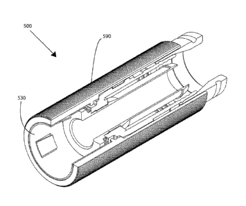
[0027] With continued reference to the drawings, FIGs. 11A and 11B depict
an
embodiment of connector 500 including a coupling member 530 and an outer
sleeve 590.
Embodiments of coupling member 530 may share the same or substantially the
same structure
and function as coupling member 30. However, embodiments of coupling member
530 may be
configured to mate with an outer sleeve 590. The coupling member 530 may have
an annular
groove or surface feature that cooperates with a groove or surface feature of
the sleeve 590 to
operably connect the outer sleeve 590 with the coupling member 530.
Alternatively, the two
components 530, 590 may be press-fit or rely on interference fit to operably
connect. Operable
connection between the coupling member 530 and outer sleeve 590 means that
rotation or
twisting of the outer sleeve 590 results in rotation of twisting of the
coupling member 530, which
can assist a user rotate the coupling member 530 in a reverse direction to
disengage from the port
20. The outer sleeve 590 may have outer surface features to facilitate
gripping of the outer
sleeve 590.
[0028] Referring to FIGs. 1-12, a method of retaining a connector 100
onto a port 20 in
an axial direction, may include the steps of providing a post 40 configured to
receive a center
conductor 18 surrounded by a dielectric 16 of a coaxial cable 10, a connector
body 50 attached to
the post 40, a coupling member 30 attached to the post 40, wherein the
coupling member 30 has
a first end 31 and second end 32, and forming one or more resilient contacts
80 on the coupling
member 30, wherein the resilient contacts 80 are configured to pass over the
external threads 24
in a first axial direction, and physically engage the external threads 24 in a
second axial
direction. The method may further include the step of facilitating continuity
through the coaxial
cable connector 100, wherein facilitating continuity includes forming one or
more resilient
14
CA 02838847 2013-12-06
WO 2012/170861 PCT/US2012/041623
protrusions 70 proximate the second end 32 of the coupling member 30, the
resilient protrusions
70 configured to physically and electrically contact the post 40.
[0029] While this disclosure has been described in conjunction with the
specific
embodiments outlined above, it is evident that many alternatives,
modifications and variations
will be apparent to those skilled in the art. Accordingly, the preferred
embodiments of the
present disclosure as set forth above are intended to be illustrative, not
limiting. Various changes
may be made without departing from the spirit and scope of the invention, as
required by the
following claims. The claims provide the scope of the coverage of the
invention and should not
be limited to the specific examples provided herein.