Note: Descriptions are shown in the official language in which they were submitted.
CA 02838948 2013-12-23
WO 2013/008023 1 PCT/GB2012/051660
Improvements relating to pipelaying
This invention relates to systems for aligning two or more parallel pipes,
cables or other
elongate elements during offshore operations, for example in a 'piggyback'
arrangement during pipelaying.
It is often desirable to install two or more elongate elements along the same
subsea
route, such as a primary larger-diameter pipe for carrying hydrocarbons and a
secondary smaller-diameter pipe for carrying water, gas or chemicals used to
produce
hydrocarbons.
Whilst pipes will be used as an example in this specification, an element need
not be a
pipe for carrying fluids but could instead be a cable for carrying power or
data. A
secondary element will usually be of much smaller diameter (typically <20 cm)
than a
primary element, but a difference in size between the elements is not
essential to the
invention in a broad sense.
Where elements such as pipes or cables are to follow the same route, it may be
beneficial to install the elements simultaneously. This is commonly achieved
by a
piggyback technique where one or more secondary elements are attached by a
succession of clamps to a primary element on a pipelay vessel, and the
elements are
then launched together in parallel toward the seabed.
Installation of a piggyback pipeline usually involves unspooling the secondary
pipe on a
pipelay vessel. The primary pipe may also be unspooled in a reel-lay
arrangement
although it could be fabricated on the pipelay vessel, for example in an S-lay
operation.
A typical reel-lay vessel 10 shown schematically in Figure 1 is fitted with a
storage and
deployment reel 12 for deploying a primary pipe 14 and has an adjustable lay
ramp 16
that is capable of deploying a range of products at varying lay angles, which
may be
from circa 20 to 90 to the horizontal. The inclination of the lay ramp 16 is
determined
by the depth of water in which the pipeline is being laid and by the
characteristics of the
pipeline, such as its diameter and stiffness.
In downstream succession from the reel 12, the lay ramp 16 carries a guide
chute 18
for guiding the primary pipe 14; a pipe straightener 20 for straightening the
primary pipe
14; a track-type tensioner 22 for gripping the primary pipe 14 between
articulated
CA 02838948 2014-08-12
W020131008023 2 PCT/GB2012/051660
tracks; and a hold-off clamp 24 for clamping the primary pipe 14 whenever the
tensioner 22 releases the primary pipe 14. A travelling clamp could be used
instead of
a track-type tensioner 22; references in this specification to a tensioner
should be taken
to include a travelling clamp unless the context demands otherwise.
As Figure 2 shows, a piggyback reel 26 can be fitted to a vessel 10 for
deploying a
secondary element such as a secondary pipe 28 with the primary pipe 14 when
operating in piggyback mode. In that mode, a piggyback chute 30 guides the
secondary pipe 28 and the secondary pipe 28 is brought into alignment with the
primary pipe 14, such that the secondary pipe 28 lies parallel to the primary
pipe 14
downstream of the tensioner 22. The secondary pipe 28 then lies directly above
the
longitudinal centreline of the primary pipe 14 or, when the primary pipe 14 is
vertical,
directly aft of the longitudinal centreline of the primary pipe 14. The
secondary pipe 28
is then ready to be clamped to the primary pipe 14 at work platforms in a
shelter 32 on
the lay ramp 16 between the tensioner 22 and the hold-off clamp 24.
In practice an additional straightener may be used for the secondary pipe 28
downstream of the piggyback chute 30 but this has been omitted from Figure 2
for
clarity. Also, the secondary pipe 28 may go through an additional tensioner
but such a
tensioner may not be required and has also been omitted for clarity.
In a prior art piggybacking arrangement, it is known for a secondary pipe 28
to be
diverted entirely around the tensioner 22 before being aligned with the
primary pipe.
This makes it difficult to align the secondary pipe 28 without overbending it
or requiring
additional straightening, unless there is a substantial and disadvantageous
gap under
the tensioner 22. The heavy tensioner 22 should be mounted as low as possible
on the
lay ramp 16 to aid the stability of the vessel 10.
US Patent No. 5975802 to Willis (Assignee: Stolt Comex Seaway Ltd.) discloses
a
known piggyback arrangement in detail, including the relationship between the
paths of
a primary pipe and a secondary pipe as they pass over their respective chutes
and are
brought together for clamping. In the example shown in US Patent No. 5975802,
the
primary pipe is fabricated on board the pipelay vessel and the secondary pipe
is
unspooled from a reel, although it will be clear to the skilled reader that
both pipes
could be spooled with the addition of a storage and deployment reel for the
primary
pipe, as in Figure 2.
CA 02838948 2013-12-23
WO 2013/008023 3
PCT/GB2012/051660
It is against this background that the present invention has been devised.
The invention resides in an alignment tool for aligning a secondary elongate
element
with a primary elongate element for subsea laying of the elements in a
piggybacked
arrangement, wherein the tool comprises:
a support structure arranged to embrace the primary element, the support
structure having an opening for accommodating the primary element such that
the primary element can move longitudinally through the opening in a launching
direction; and
attachment points for supporting the tool to maintain or control its
longitudinal
and/or angular position with respect to the primary element as the primary
element moves through the opening.
The tool is preferably arranged such that the primary element supports the
tool as the
primary element moves in the launching direction through the opening in the
support
structure. For example, the tool suitably has having rollers around the
opening of the
support structure to bear against the primary element in use.
Advantageously, the tool is arranged to be suspended by chains, wires or the
like at
the attachment points.
The support structure is suitably a ring for encircling the primary element.
The ring is
preferably in separable parts that may be assembled around the primary
element.
The support structure preferably lies generally in a plane that is
substantially
orthogonal to the launching direction of the primary element.
The tool of the invention may further comprise a guide on the support
structure for
rerouting the secondary element from a first angular position to a second
angular
position with respect to the primary element. The guide is preferably movable
radially
with respect to the support structure; for example, the guide may comprise a
tube
having a base movable along a radially-extending slot in the support structure
for
accommodating the secondary element.
CA 02838948 2013-12-23
WO 2013/008023 4 PCT/GB2012/051660
The invention extends to an alignment system for aligning a secondary elongate
element with a primary elongate element for subsea laying of the elements in a
piggybacked arrangement, the system comprising the alignment tool of any
preceding
claim, mounted downstream of a tensioner on a lay ramp of a vessel. In that
system,
the tool is conveniently suspended from a support structure of the tensioner
and may
be mounted upstream of a work region where the secondary element is attached
to the
primary element.
Where the tensioner comprises a plurality of tracks aligned generally with,
and spaced
apart around, the primary element, at least one of the tracks being above the
primary
element, the secondary element is advantageously fed to the tool along a space
between neighbouring tracks of the tensioner and is guided by the tool to a
position
above the primary element.
The invention also embraces a method of aligning a secondary elongate element
with a
primary elongate element for subsea laying of the elements in a piggybacked
arrangement, comprising feeding the secondary element at a first angular
position with
respect to the primary element along a space between neighbouring tracks of a
tensioner and then guiding the secondary element into a second angular
position with
respect to the primary element for attachment to the primary element.
To describe the state of the art, reference has already been made to Figures 1
and 2
of the accompanying drawings, in which:
Figure 1 is a schematic side view of a typical reel-lay vessel; and
Figure 2 is a schematic side view of a reel-lay vessel adapted for piggyback
pipe laying.
In order that the invention may readily be understood, reference will now be
made, by
way of example, to the remaining drawings in which:
Figure 3 is a schematic side view showing an alignment tool in accordance with
the invention in use on a pipelaying vessel to bring a secondary pipe into
alignment with a primary pipe for clamping;
CA 02838948 2013-12-23
WO 2013/008023 5 PCT/GB2012/051660
Figure 4 is a schematic perspective view of the alignment tool of Figure 3 in
use; and
Figure 5 is a schematic cross-sectional view of the alignment tool of Figure 3
in
use.
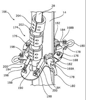
Figures 3 to 5 of the drawings show an alignment tool 166 in accordance with
the
invention for bringing a secondary pipe 28 or other element into alignment
with a
primary pipe 14 or other element. It will be recalled that the secondary pipe
28 needs to
be parallel to the primary pipe 14 downstream of the tensioner 22, at a
position directly
above the longitudinal centreline of the primary pipe 14 when the primary pipe
14 is
inclined. When the primary pipe 14 is vertical, the secondary pipe 28 needs to
be
directly aft of the longitudinal centreline of the primary pipe 14.
Once aligned in this way, the secondary pipe 28 is then ready to be clamped to
the
primary pipe 14 in a shelter 32 on the lay ramp 16 before the piggybacked pipe
is
launched into the sea. The alignment tool 166 may be used with manual clamping
techniques or the shelter 32 may contain apparatus for automated clamping.
The alignment tool 166 of the invention aims for simplicity, compactness and
effectiveness. Simplicity ensures reliability, low cost and ease of mounting
to existing
structures on the lay ramp 16 without major adaptation. Compactness maximises
space utilisation on the lay ramp 16 and in particular leaves ample room for
clamping
apparatus in the shelter 32 while allowing the heavy tensioner 22 to be
mounted as low
as possible on the lay ramp 16 to lower the centre of gravity of the pipelay
vessel for
stability. Effectiveness ensures that the secondary pipe 28 is routed
efficiently and
without overbending or exceeding the minimum bend radius of the secondary pipe
28.
With particular reference to Figure 3, the alignment tool 166 comprises a
generally flat
ring 168 surrounding the primary pipe 14 in a plane substantially orthogonal
to the
direction of movement of the primary pipe 14 along the lay ramp 16. The
alignment tool
166 lies compactly between a tensioner 22 and a shelter 32 mounted on the lay
ramp
where the primary and secondary pipes 14, 28 are clamped together. Four chains
170
equi-spaced around the ring 168 hang the ring 168 from the supporting
structure of the
tensioner 22. Only two of the chains 170 are visible in this side view.
CA 02838948 2013-12-23
WO 2013/008023 6 PCT/GB2012/051660
The tensioner 22 shown in Figure 3 is a four-track tensioner in which four
articulated
tracks 172 surround the primary pipe 14: a top track 172A above; a bottom
track 172B
below; and two side tracks 1720, one to each side. Only one of the side tracks
1720 is
visible in this side view.
In a prior art piggybacking arrangement, it is known for a secondary pipe 28
to be
diverted entirely around a tensioner 22 before being aligned with the primary
pipe 14.
This makes it difficult to align the secondary pipe 28 without overbending it
or requiring
additional straightening. In contrast, the arrangement shown in Figure 3 runs
the
secondary pipe 28 along the narrow gap between the top track 172A and one of
the
side tracks 1720 of the tensioner 22. Consequently the alignment tool 166 need
only
move the secondary pipe 28 about 45 around the primary pipe 14 from its
position
immediately downstream of the tensioner 22 to its position directly above or
aft of the
primary pipe 14, ready for clamping to the primary pipe 14 in the shelter 32.
This minimal deflection of the secondary pipe 28 is advantageous as it avoids
imparting
excessive bending stress to the secondary pipe 28; it also effects the
necessary
alignment of the secondary pipe 28 in a short length parallel to the lay ramp
16, to the
benefit of compactness.
The secondary pipe 28 runs in an articulated guide tube 174 attached to the
ring 168 of
the alignment tool 166. Further details of the guide tube 174 are evident from
the detail
views of the alignment tool 166 in Figures 4 and 5, to which specific
reference is now
made.
Figures 4 and 5 show that the ring 168 of the alignment tool 166 is in two
largely
semicircular C-shaped parts 168A, 168B that are coupled to each other around
the
primary pipe 14 by diametrically-opposed bolts 176. Each part 168A, 168B has
radially-
extending lugs 178 at 90 to each other, each lug 178 supporting a shackle 180
for
attaching one of the aforementioned chains 170.
Inboard of each lug 178, a pair of rollers 182 is mounted on a support 184 to
overlap
the inner edge 186 of the ring 168. The four pairs of rollers 182 bear against
the
primary pipe 14 with rolling contact to support the alignment tool 166 in use.
One of the parts 168A has a U-shaped radial extension 188 having a radially-
extending
slot 190 that opens into the central aperture 192 of the ring 168. The slot
190
CA 02838948 2013-12-23
WO 2013/008023 7
PCT/GB2012/051660
surrounds and accommodates the secondary pipe 28, which runs in the
articulated
guide tube 174 upstanding from the extension 188. Specifically, the extension
188 has
parallel rails 194 disposed one each side of the slot 190, between which a T-
section
base 196 of the guide tube 174 can move radially to adjust the radial position
of the
secondary pipe 28 with respect to the primary pipe 14. The radial position of
the base
196 of the guide tube 174 is adjusted by screws 198 parallel to and between
the rails
194, that engage with respective T-section arms of the base 196. The rails 194
have
upper flanges 200 that overlap the T-section arms of the base 196 to hold the
guide
tube 174 on the radial extension 188.
The articulated guide tube 174 comprises segments 202 and a succession of
joint
collars 204 between the segments 202. The lowermost segment includes the T-
section
base 196. The segments 202 may, for example, be of cast iron, steel or
plastics. They
may be rigid or flexible, and may be coated or uncoated depending on the
nature of the
secondary pipe 28 or other secondary element.