Note: Descriptions are shown in the official language in which they were submitted.
CA 02839147 2013-12-12
WO 2013/006177 PCT/US2011/043156
IMPROVED ELECTRICAL CONFIGURATION FOR A VIBRATING METER
TECHNICAL FIELD
The embodiments described below relate to, vibrating meters, and more
particularly, to an improved electrical configuration for a vibrating meter.
BACKGROUND OF THE INVENTION
Vibrating meters, such as for example, vibrating densitometers and Coriolis
flow
meters are generally known and are used to measure mass flow and other
information
for materials within a conduit. The meter comprises a sensor assembly and an
electronics portion. The material within the sensor assembly may be flowing or
stationary. Each type of sensor may have unique characteristics, which a meter
must
account for in order to achieve optimum performance.
Exemplary Coriolis flow meters are disclosed in U.S. Patent 4,109,524, U.S.
Patent 4,491,025, and Re. 31,450 all to J.E. Smith et al. These flow meters
have one or
more conduits of straight or curved configuration. Each conduit configuration
in a
Coriolis mass flow meter has a set of natural vibration modes, which may be of
simple
bending, torsional, or coupled type. Each conduit can be driven to oscillate
at a
preferred mode.
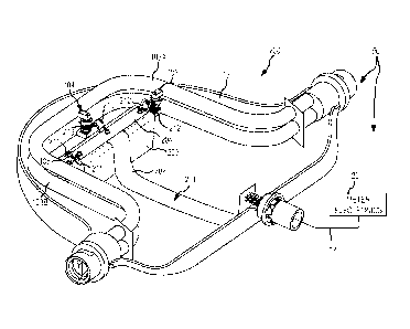
FIG. 1 shows a prior art sensor assembly 10. The sensor assembly 10 is
typically in electrical communication with a meter electronics 20 to form a
vibrating
meter 5. While the sensor assembly 10 is described below as comprising a
portion of a
Coriolis flow meter, it should be appreciated that the sensor assembly 10
could just as
easily be utilized as another type of vibrating meter. The sensor assembly 10
receives a
flowing fluid; however, sensor assemblies of vibrating meters are not
necessarily limited
to a structure where a fluid under test is flowing. Therefore, the sensor
assembly 10
may comprise the vibrating portion of a vibrating densitometer where the fluid
is not
flowing, the sensing portion of ultra-sonic flow meters, the sensing portion
of magnetic
volumetric flow meters, etc.
The meter electronics can be connected to the sensor assembly 10 to measure
one
or more characteristics of a flowing material, such as, for example, density,
mass flow
rate, volume flow rate, totalized mass flow, temperature, and other
information.
1
CA 02839147 2013-12-12
WO 2013/006177 PCT/US2011/043156
The front half of the sensor assembly's case 15 is removed in FIG. 1 to show
the
interior components. The sensor assembly 10 includes a pair of manifolds 102
and
102', and conduits 103A and 103B. Manifolds 102, 102' are affixed to opposing
ends
of the conduits 103A and 103B. The conduits 103A and 103B extend outwardly
from
the manifolds in an essentially parallel fashion. When the sensor assembly 10
is
inserted into a pipeline system (not shown) which carries the flowing
material, the
material enters sensor assembly 10 through the inlet manifold 102 where the
total
amount of material is directed to enter conduits 103A, 103B, flows through the
conduits
103A, 103B and back into the outlet manifold 102' where it exits the sensor
assembly
10.
The sensor assembly 10 can include a driver 104. The driver 104 is shown
affixed to conduits 103A, 103B in a position where the driver 104 can vibrate
the
conduits 103A, 103B in the drive mode, for example. The driver 104 may
comprise one
of many well-known arrangements such as a coil mounted to the conduit 103A and
an
opposing magnet mounted on the conduit 103B. A drive signal in the form of an
alternating current can be provided by the meter electronics 20, such as for
example via
first and second wire leads 110, 110', and passed through the coil to cause
both conduits
103A, 103B to oscillate about bending axes W-W and W'-W'. The wire leads 110
and
110' are coupled to the driver 104 and a first printed circuit board (PCB)
106. Generally
the wire leads are coupled to the first PCB 106 and the driver 104 by
soldering. A
second set of wire leads 120 and 120' couple the first PCB to a second PCB
107. The
second PCB 107 is in electrical communication with the meter electronics via
leads 130.
The prior art electrical configuration for the driver 104 shown requires four
wire leads
and two PCBs 106 and 107, resulting in eight soldered joints prior to exiting
the sensor
assembly's case 15.
The sensor assembly 10 also includes a pair of pick-off sensors 105, 105' that
are
affixed to the conduits 103A, 103B. According to an embodiment, the pick-off
sensors
105, 105' may be electromagnetic detectors, for example, pick-off magnets and
pick-off
coils that produce sensor signals that represent the velocity and position of
the conduits
103A, 103B. For example, the pick-off sensors 105, 105' may supply pick-off
signals
to the meter electronics 20 via pathways 111, 111', 112, and 112', which
provide an
electrical communication path between the pick-off sensors 105, 105' and the
first PCB
2
CA 02839147 2013-12-12
WO 2013/006177 PCT/US2011/043156
106. A second set of wire leads 121, 121', 122, and 122' provide electrical
communication between the first and second PCBs 106 and 107 for the pick-off
sensors
105, 105'. Therefore, the electrical configuration requires eight wire leads
for a total of
sixteen solder joints for the pick-off sensors 105, 105' prior to exiting the
sensor
assembly's case 15. The power to/from the driver 104 and pick-off sensors 105,
105'
can be regulated using resistors 115, which are shown coupled to the first PCB
106.
Additionally shown are wire leads 113, 113' for a temperature sensing device
such as a resistance temperature detector (RTD) (not shown) that is coupled to
the
second PCB 107. In some prior art sensor assemblies, the wire leads are also
held to the
case 15 by tape 114 or some other adhering means to restrict the movement of
the leads
irrespective of the sensor assembly's orientation.
Those of ordinary skill in the art will appreciate that the motion of the
conduits
103A, 103B is proportional to certain characteristics of the flowing material,
for
example, the mass flow rate and the density of the material flowing through
the conduits
103A, 103B.
According to an embodiment, the meter electronics receives the pick-off
signals
from the pick-off sensors 105, 105'. A path 26 can provide an input and an
output
means that allows one or more meter electronics 20 to interface with an
operator. The
meter electronics 20 can measure one or more characteristics of the fluid
under test such
as, for example, a phase difference, a frequency, a time delay (phase
difference divided
by frequency), a density, a mass flow rate, a volume flow rate, a totalized
mass flow, a
temperature, a meter verification, and other information as is generally known
in the art.
For example, as material flows into the sensor assembly 10 from a connected
pipeline on the inlet side of the sensor assembly 10, it is directed through
the conduit
103A, 103B, and exits the sensor assembly 10 through the outlet side of the
sensor. The
natural vibration modes of the vibrating material filled system are defined in
part by the
combined mass of the conduits and the material flowing within the conduits.
When there is no flow through the sensor assembly, a driving force applied to
the
conduits 103A, 103B by the driver 104 causes all points along the conduits
103A, 103B
to oscillate with identical phase or small "zero offset," which is a time
delay measured
at zero flow. As material begins to flow through the sensor assembly, Coriolis
forces
cause each point along the conduit(s) to have a different phase. For example,
the phase
3
CA 02839147 2013-12-12
WO 2013/006177 PCT/US2011/043156
at the inlet end of the sensor lags the phase at the centralized driver
position, while the
phase at the outlet leads the phase at the centralized driver position. Pick-
off sensors
105, 105' on the conduits 103A, 103B produce sinusoidal signals representative
of the
motion of the conduits 103A, 103B. Signals output from the pick-off sensors
105, 105'
are processed to determine the phase difference between the pick-off sensors
105, 105'.
The phase difference between the two or more pick-off sensors 105, 105' is
proportional
to the mass flow rate of the material flowing through the conduits 103A, 103B.
The mass flow rate of the material can be determined by multiplying the phase
difference by a Flow Calibration Factor (FCF). Prior to installation of the
sensor
assembly 10 of the flow meter into a pipeline, the FCF is determined by a
calibration
process. In the calibration process, a fluid is passed through the flow
conduits 103A,
103B at a known flow rate and the relationship between the phase difference
and the
flow rate is calculated (i.e., the FCF). The sensor assembly 10 of the flow
meter 5
subsequently determines a flow rate by multiplying the FCF by the phase
difference of
the pick-off sensors 105, 105'. In addition, other calibration factors can be
taken into
account in determining the flow rate.
Due, in part, to the high accuracy of vibrating meters, and Coriolis flow
meters in
particular, vibrating meters have seen success in a wide variety of
industries. However,
as mentioned above, the sensor assembly' s electrical configuration to
communicate with
the driver 104 and pick-off sensors 105, 105' requires an excessive number of
wire leads
and solder joints. The solder joint typically restricts the temperature range
the sensor
assembly is capable of handling. Further because each wire lead is typically
cut and
soldered individually by hand, sensor assemblies are subject to wide
variability from
one sensor assembly to another. Another problem with the prior art electrical
configuration is that the wire leads from the first PCB 106 to the driver 104
and pick-off
sensors 105, 105' are subject to an excessive amount of strain that often
leads to
premature failure. If a single wire lead breaks, the entire sensor assembly 10
is typically
rendered inoperable.
The embodiments described below overcome these and other problems and an
advance in the art is achieved. The embodiments described below provide an
improved
electrical configuration for a sensor assembly that results in a cheaper, more
efficient,
and more reliable sensor assembly. The improved sensor assembly utilizes a
flexible
4
CA 02839147 2013-12-12
WO 2013/006177 PCT/US2011/043156
circuit rather than a rigid PCB with various wire leads. Additionally, in some
embodiments, the flexible circuit can withstand higher temperatures than the
prior art
wire leads that are soldered to the sensor components.
SUMMARY OF THE INVENTION
A sensor assembly for a vibrating meter is provided according to an
embodiment.
The sensor assembly comprises one or more conduits and one or more sensor
components including one or more of a driver, a first pick-off sensor, and a
second pick-
off sensor coupled to the one or more conduits. According to an embodiment,
the
sensor assembly further includes a flexible circuit. The flexible circuit
includes a body
and one or more sensor component flexures extending from the body and coupled
to a
sensor component of the one or more sensor components.
A method for assembling a sensor assembly is provided according to an
embodiment. The method comprises steps of positioning one or more conduits
within a
case and coupling one or more sensor components to the one or more conduits,
the
sensor components including one or more of a driver, a first pick-off sensor,
and a
second pick-off sensor. According to an embodiment, the method further
comprises a
step of positioning a flexible circuit within the case. According to an
embodiment, the
method further comprises a step of coupling one or more sensor component
flexures
extending from a body of the flexible circuit to a sensor component of the one
or more
sensor components.
ASPECTS
According to an aspect, a sensor assembly for a vibrating meter comprises:
one or more conduits;
one or more sensor components including one or more of a driver, a first pick-
off
sensor, and a second pick-off sensor coupled to the one or more conduits;
and
a flexible circuit including:
a body; and
5
CA 02839147 2013-12-12
WO 2013/006177 PCT/US2011/043156
one or more sensor component flexures extending from the body and
coupled to a sensor component of the one or more sensor
components.
Preferably, the flexible circuit provides electrical communication between a
Preferably, each of the sensor component flexures includes at least one
coupling
aperture adapted to receive at least a portion of a sensor component pin.
Preferably, the sensor assembly further comprises a strain relief coupled to a
sensor component flexure such that a portion of the flexure coupled to the
stain relief
Preferably, the strain relief comprises a plate coupled to a conduit bracket
of a
sensor component with at least a portion of the sensor component flexure
positioned
between the plate and the conduit bracket.
15 Preferably, the sensor assembly further comprises a tubular rivet
received in each
of the coupling apertures of the sensor component flexure.
Preferably, the tubular rivet received in the coupling apertures is further
coupled
to the sensor component pin.
Preferably, each of the sensor component flexures comprises one or more
Preferably, the sensor assembly further comprises a redundant flexure coupled
to
the at least one sensor component flexure.
Preferably, each of the sensor component flexures comprises a primary
electrical
trace and a redundant electrical trace.
25 According to another aspect, a method for assembling a sensor assembly
comprises steps of:
positioning one or more conduits within a case;
coupling one or more sensor components to the one or more conduits, the sensor
components including one or more of a driver, a first pick-off sensor, and
30 a second pick-off sensor;
positioning a flexible circuit within the case; and
6
CA 02839147 2013-12-12
WO 2013/006177 PCT/US2011/043156
coupling one or more sensor component flexures extending from a body of the
flexible circuit to a sensor component of the one or more sensor
components.
Preferably, the method further comprises coupling the flexible circuit to a
meter
electronics to provide electrical communication between the meter electronics
and the
one or more sensor components.
Preferably, the step of coupling the one or more sensor component flexures
comprises inserting a sensor component pin extending from a sensor component
into a
coupling aperture formed in the sensor component flexure.
Preferably, the method further comprises a step of coupling a sensor component
flexure to a strain relief such that a portion of the sensor component flexure
coupled to
the strain relief and the coupling aperture remain substantially stationary
with respect to
one another during vibration of the one or more conduits.
Preferably, the strain relief is coupled to a sensor component.
Preferably, the strain relief comprises a plate and the step of coupling the
sensor
component flexure to the strain relief comprises positioning a portion of the
sensor
component flexure between the plate and a conduit bracket of the sensor
component.
Preferably, the method further comprises a step of inserting a tubular rivet
into
each of the coupling apertures formed in the sensor component flexure.
Preferably, the method further comprises a step of coupling the tubular rivet
to
the sensor component pin.
Preferably, each of the sensor component flexures comprises one or more
electrical traces.
Preferably, the flexible circuit further comprises a redundant flexure coupled
to
the at least one sensor component flexure.
Preferably, each of the sensor component flexures comprises a primary
electrical
trace and a redundant electrical trace.
BRIEF DESCRIPTION OF THE DRAWINGS
FIG. 1 shows a prior art sensor assembly.
FIG. 2 shows a sensor assembly for a vibrating meter according to an
embodiment.
7
CA 02839147 2013-12-12
WO 2013/006177 PCT/US2011/043156
FIG. 3 shows the flexible circuit coupled to a sensor component of the sensor
assembly according to an embodiment.
FIG. 4 shows the flexible circuit coupled to the sensor component according to
another embodiment.
FIG. 5 shows a sensor component flexure of the flexible circuit according to
an
embodiment.
FIG. 6 shows the sensor component flexure of the flexible circuit according to
another embodiment.
FIG. 7 shows a cross-sectional view of a flexure coupled to a coil pin using a
tubular rivet according to an embodiment.
DETAILED DESCRIPTION OF THE INVENTION
FIGS. 2 ¨ 7 and the following description depict specific examples to teach
those
skilled in the art how to make and use the best mode of embodiments of a
sensor
assembly. For the purpose of teaching inventive principles, some conventional
aspects
have been simplified or omitted. Those skilled in the art will appreciate
variations from
these examples that fall within the scope of the present description. Those
skilled in the
art will appreciate that the features described below can be combined in
various ways to
form multiple variations of the sensor assembly. As a result, the embodiments
described
below are not limited to the specific examples described below, but only by
the claims
and their equivalents.
FIG. 2 shows a vibrating meter 50 including the meter electronics 20 and a
sensor assembly 200 according to an embodiment. Common reference numbers are
used for components of the sensor assembly 200 that also comprise components
of the
prior art sensor assembly 10. The embodiment shown in FIG. 2 has the front
half of the
case 15 removed in order to illustrate the interior components. As shown, the
sensor
assembly 200 has eliminated both the first and second PCBs 106, 107 as well as
the wire
leads. Rather, the sensor components are coupled to a flexible circuit 201,
sometimes
referred to in the art as "flex circuit." According to an embodiment, the
sensor
components are in electrical communication with the meter electronics 20 via
the
flexible circuit 201. The sensor components may include one or more of the
driver 104,
the pick-off sensors 105, 105', and the RTD (not shown), for example.
According to an
8
CA 02839147 2013-12-12
WO 2013/006177 PCT/US2011/043156
embodiment, the flexible circuit 201 can be formed as a one-piece component.
The
flexible circuit 201 can include a main body 202 and one or more sensor
component
flexures 210-212' extending from the main body 202. The flexible circuit 201
can
communicate between the leads 130 and the sensor components. Therefore, in
some
embodiments, the flexible circuit 201 can be coupled to the plurality of leads
130. The
leads 130 can provide an electrical communication path between the flexible
circuit 201
and the meter electronics 20, for example. Alternatively, the leads 130 may be
eliminated and the flexible circuit 201 may extend out of the case 15 to the
meter
electronics 20. Therefore, the flexible circuit 201 provides electrical
communication
between the sensor components and devices external to the sensor assembly 200,
such
as the meter electronics 20. Consequently, the flexible circuit 201 has
replaced the wire
leads 110-122' along with the two PCBs 106, 107 of the prior art sensor
assembly 10.
According to an embodiment, the flexible circuit 201 can comprise a flexible
flat
cable, a ribbon cable, etc. The flexible circuit 201 may comprise one or more
thin,
flexible, insulating substrates, such as polyethylene, Polyethylene
terephthalate (PET),
or some other plastic or insulating material well-known in the art. The
flexible circuit
201 can comprise a plurality of electrical traces (See FIGS. 5 & 6). The
electrical traces
may be contained within two insulating flexible substrates, i.e., sandwiched
between
two layers of the flexible substrate. A common example of a flexible circuit
is known
with metallic traces bonded, laminated, etched, etc. to a flat and flexible
plastic
substrate. The metallic traces may comprise copper films, photo-etched or
plated
copper films, or some other material generally known in the art that can be
used as an
electrical trace to carry power, signals, and/or ground. The particular
configuration of
the flexible circuit 201 may vary depending upon the number of electrical
traces
required and the particular configuration. Therefore, the specific
configuration shown in
FIG. 2 should in no way limit the scope of the present embodiment.
Unlike a rigid PCB, the flexible circuit 201 is resilient and can deform or
otherwise flex to accommodate various configurations. The flexible circuit 201
can
therefore, relieve a substantial amount of stress seen in the prior art
electrical
configuration.
According to an embodiment, the sensor assembly 200 can further include a
mounting block 203. According to an embodiment, at least a portion of the
flexible
9
CA 02839147 2013-12-12
WO 2013/006177 PCT/US2011/043156
circuit 201 can be mounted on the mounting block 203. More specifically, a
portion of
the main body 202 of the flexible circuit 201 can be mounted on the mounting
block
203. The flexible circuit 201 can be retained on the mounting block 203 using
a
mounting plate 204 or similar device. According to an embodiment, a portion of
the
main body 202 can be mounted on the mounting block 203 in order to
substantially
center the flexible circuit 201 with respect to the case 15, for example. For
example, the
mounting block 203 can be provided to center a portion of the flexible circuit
201
between the two conduits 103A, 103B.
According to an embodiment, the flexible circuit 201 can be coupled to the
sensor components 104, 105, 105' using a plurality of sensor component
flexures. In
the embodiment shown, the flexible circuit 201 is coupled to the driver 104
using first
and second driver flexures 210, 210'. Likewise, the flexible circuit 201 is
coupled to the
pick-off sensors 105, 105' using first and second pick-off flexures 211, 211'
and 212,
212', respectively. The flexures may comprise a similar configuration as the
main body
202 of the flexible circuit 201. However, the flexures may be limited to
including
electrical traces for the particular sensor component being coupled while the
main body
202 can include substantially all of the electrical traces required. According
to an
embodiment, the flexures can comprise integral components to the main body 202
of the
flexible circuit 201. As shown, the flexures can extend from the main body
202.
Therefore, the flexures do not require separate soldering joints as required
between the
wire leads and the PCBs of the prior art sensor assembly 10. Rather, the
flexures only
need to be coupled to the associated sensor component. The flexures can
provide both
physical and electrical coupling between the flexible circuit 201 and the
sensor
components. As can be appreciated, unlike prior art wire leads that are
susceptible to
differences in length as the wire leads are being soldered to the sensor
components and
the PCB, the flexures can comprise an integral component of the flexible
circuit 201.
The flexible circuit 201, including the flexures, can be formed in a
reproducible manner
with substantially uniform size and length from one flexible circuit to
another.
It should be appreciated, that although not shown in FIG. 2, in some
embodiments, the flexible circuit 201 may include a plurality of electrical
resistors,
similar to the resistors 115 shown in FIG. 1, in order to regulate the power
delivered to
the sensor components.
CA 02839147 2013-12-12
WO 2013/006177 PCT/US2011/043156
FIG. 3 shows a more detailed view of the coupling between the flexible circuit
201 and a sensor component. In the embodiment shown in FIG. 3, the sensor
component comprises the second pick-off sensor 105'. However, it should be
appreciated that similar couplings can be made to the other sensor components,
i.e., the
driver 104, the first pick-off sensor 105, and the RTD.
According to the embodiment shown, the pick-off sensor 105' comprises a
coil/magnet configuration with the pick-off coil 305A coupled to the first
flow conduit
103A and the pick-off magnet 305B coupled to the second flow conduit 103B. It
should
be appreciated, however, that other types of drivers and pick-off sensors may
be used,
such as optical, piezoelectric, etc. Therefore, the embodiments described
should not be
limited to electromagnetic sensor components; rather, coil/magnet
configurations are
referred to in the present description to maintain consistency.
As shown, the first and second pick-off flexures 212, 212' are coupled to
first
and second sensor component pins 312, 312'. Therefore, the coupling of the
first and
second pick-off flexures 212, 212' has replaced the coupling of the wire leads
112, 112'
to the first and second pins 312, 312' of the coil seen in the prior art
sensor assembly 10
shown in FIG. 1. According to an embodiment, the coupling between the first
and
second pick-off flexures 212, 212' and the first and second pins 312, 312' can
be
accomplished by soldering the flexures 212, 212' to the first and second pins
312, 312'.
More specifically, the flexures 212, 212' can include coupling apertures 330,
330' that
are sized and shaped to receive at least a portion of the first and second
pins 312, 312' of
the coil 305A. The coupling apertures 330, 330' can comprise electrically
conductive
portions that allow suitable electrical communication between the traces (See
FIGS. 5 &
6) of the first and second flexures 212, 212' and the first and second pins
312, 312' of
the coil 305A. However, those skilled in the art can readily appreciate
alternative
configurations. The coupling between the flexures 212, 212' and the pins 312,
312'
provides an electrical as well as physical coupling between the flexible
circuit 201 and
the pick-off sensor 105'.
While soldering may provide sufficient coupling in some circumstances, as
mentioned above, in some higher temperature applications, soldered joints can
be
compromised as the soldering material can melt. Therefore, in some situations,
soldering the coil pins 312, 312' directly to the flexures 212, 212' may
result in a
11
CA 02839147 2013-12-12
WO 2013/006177 PCT/US2011/043156
limited temperature range for the sensor assembly 200. Therefore, according to
an
embodiment, the flexures 212, 212' can be provided with tubular rivets 331,
331'. The
tubular rivets 331, 331' are shown surrounding the coupling apertures 330, 330
in FIG.
3 and are shown in greater detail in the cross-sectional view shown in FIG. 7.
According to an embodiment, the first and second flexures 212, 212' are also
coupled to one another via a redundancy flexure 350. The redundancy flexure
350 can
create a redundant circuit as explained in more detail below. The redundancy
flexure
350 provides a completed electrical circuit even in the event that one of the
flexures
212,212' is broken.
The configuration shown in FIG. 3 reduces the stress applied to the soldered
joint
compared to the prior art situation. The flexures 212, 212' are more reliable
than the
prior art wire leads as the flexures 212, 212' can distribute the load caused
by vibration
more efficiently than the prior art wire leads, thereby reducing the stress
created as the
flow conduits 103A, 103B vibrate. Additionally, the flexures 212, 212'
comprise an
integrally formed portion of the flexible circuit 201 resulting in more
uniform and
reproducible lengths for the flexures 212, 212' than was possible for the
independent
wire leads shown in FIG. 1. This can reduce the stress compared to the prior
art wire
leads, because if the prior art wire leads is too short, resulting in a tight
radii, the
soldered joint will experience an increased stress during vibration. The
flexures 212,
212' of the flexible circuit 201 can also reduce the risk of kinking as seen
in the prior art
wire leads, which often leads to a stress riser in the wire lead. However,
while the
flexures 212, 212' shown in FIG. 3 reduce the physical stress on the solder
joints, the
solder joints may still experience some strain in order to retain the first
and second
contacts 312, 312' within the coupling apertures 330, 330' as the conduits
103A, 103B
vibrate.
FIG. 4 shows the flexures 212, 212' coupled to a sensor component according to
another embodiment. In the embodiment shown in FIG. 4, the flexures 212, 212'
are
coupled to a strain relief 440. According to an embodiment, the strain relief
440 can
comprise a portion of the coil 305A. More specifically, the stain relief 440
can be
formed on a conduit bracket 405A of the coil 305A. According to another
embodiment,
the strain relief 440 can be coupled to a portion of the coil 305A. In the
embodiment
shown, the strain relief 440 is coupled to the redundant flexure 350 that
joins the
12
CA 02839147 2013-12-12
WO 2013/006177 PCT/US2011/043156
flexures 212, 212'. The redundant flexure 350 is shown slightly larger in the
embodiment of FIG. 4 than in the embodiment shown in FIG. 3 in order to
accommodate the strain relief 440. However, the stain relief 440 does not have
to be
coupled to the redundant flexure 350 and may be coupled to the first and
second
flexures 212, 212'. A strain relief as shown in FIG. 4 was not feasible in the
prior art
because contact with the wire leads could cause a short circuit. However, the
flexible
circuit 201 comprises the insulating substrate that can prevent or
substantially reduce the
risk of a short circuit. Consequently, the strain relief 440 can be used.
With the stain relief 440 coupled to the flexures 212, 212', the solder joints
at the
coupling apertures 330, 330' and the first and second coil pins 312, 312'
experience a
substantially reduced amount of strain. This is because, as the flow conduits
103A,
103B vibrate, the relative position between the stain relief 440 and the
contacts 312,
312' remain stationary. In other words, the relative position of the portion
of the
flexures 212, 212' coupled to the strain relief 440 and the first and second
contacts 312,
312' remains substantially constant, even during vibration of the conduits
103A, 103B.
Consequently, during vibrations, the coupling between the coupling apertures
330, 330'
and the first and second pins 312, 312' are not subject to pulling or any
other type of
deformation. Rather, the pulling and deformation is experienced between the
strain
relief and the mounting plate 204. As can be appreciated, because the flexures
212,
212' comprise part of the flexible circuit, which is capable of deformation,
the
vibrations, and excessive movements are easily accommodated.
According to the embodiment shown, the strain relief 440 comprises a plate 441
that can be coupled to the conduit bracket 405A of the sensor component 305A
with the
flexures 212, 212', and more specifically, the redundant flexure 350
sandwiched
between the plate 441 and the conduit bracket 405A. While a single plate 441
is shown,
it should be appreciated that in other embodiments, the flexures 212, 212' may
not be
joined with the redundant flexure 350 and thus, multiple plates can be
provided.
Furthermore, while the stain relief 440 of the presently described embodiment
utilizes a
plate 441, it should be appreciated that other configurations may be used to
couple a
portion of the flexures 212, 212' to the conduit bracket 405A. For example,
the
redundant flexure 350 may be coupled to the conduit bracket 405A using an
adhesive,
clip, projection and corresponding aperture, etc. Advantageously, the strain
relief 440
13
CA 02839147 2013-12-12
WO 2013/006177 PCT/US2011/043156
can extend the life of the sensor assembly 200, and in particular the life of
the coupling
between the flexible circuit 201 and the various sensor components.
As mentioned briefly above, the flexible circuit 201 of the present embodiment
can include redundant circuitry. The redundant circuitry allows power,
signals, and/or
ground to be delivered between the meter electronics 20 and the sensor
components
even if one of the flexures to the sensor component is broke.
FIG. 5 shows a cross-sectional view of the flexures 212, 212' according to an
embodiment. As shown in FIG. 5, the flexible circuit 201 includes two
electrical traces
512 and 512'. The electrical traces 512, 512' can provide electrical
communication
between a sensor component, such as the pick-off sensor 105' and the meter
electronics
20, for example. In some embodiments, the electrical traces 512, 512' may
provide
electrical communication between a sensor component and another intermediary
electrical component, such as the leads 130, for example. Therefore, while
only two
electrical traces 512, 512' are shown, those skilled in the art will readily
recognize that
two or more traces can be provided for each of the sensor components coupled
to the
flexible circuit 201.
According to the embodiment shown, one of the electrical traces can comprise a
reference voltage, such as ground, and the other electrical trace can be at
some voltage
different than reference voltage as indicated by the + and ¨ signs. As shown,
both of the
electrical traces 512, 512' extend through each of the flexures 212, 212' as
well as the
redundant flexure 350. The first electrical trace 512 separates into a primary
trace 512A
that extends through the flexure 212 and a redundant trace 512B that extends
through
the flexure 212' and the redundant flexure 350 to provide electrical
communication to
the first coupling aperture 330. Similarly, the second electrical trace 512'
separates into
a primary electrical trace 512'A that extends through the flexure 212' and a
redundant
electrical trace 512'B that extends through the flexure 212 and the redundant
flexure
350 to provide electrical communication to the second coupling aperture 330'.
As those
skilled in the art will understand, power and/or signals can travel from
either or both of
the primary first electrical trace 512A and the redundant first electrical
trace 512B to the
first coupling aperture 330. With the electrical contact 312 of the coil 305A
coupled to
the first coupling aperture 330, the power can flow through the coil 305A
towards the
14
CA 02839147 2013-12-12
WO 2013/006177 PCT/US2011/043156
second coupling aperture 330'. The primary second electrical trace 512'A
and/or the
redundant second electrical trace 512'B can complete the circuit.
FIG. 6 shows a portion of the flexible circuit 201 according to another
embodiment. In the embodiment shown in FIG. 6, the first flexure 212 has been
broken.
The flexure 212 may have broken for a number of reasons. As can be
appreciated, if the
wire lead 112 of the prior art sensor assembly 10 broke in a similar manner to
the
flexure 212, no power or signal could be communicated to the pick-off sensor
105'.
However, because the traces 512, 512'extend through both flexures 212, 212'
and not
just one of the flexures 212, 212', the broken flexure 212 does not prevent
power and/or
signals to be communicated to the pick-off sensor 105' as the other flexure
can provide
the electrical communication path. With the first flexure 212 broken, power
and/or
signals can be communicated through the redundant first electrical trace 512B
and the
primary second electrical trace 512'A. Therefore, the embodiment shown that
includes
the redundant flexure 350 creates a redundant circuit to allow continued use
after one of
the flexures breaks. Consequently, the sensor component can communicate with
the
meter electronics 20 with a single flexure 212 or 212' and the redundant
flexure 350.
FIG. 7 shows a cross-sectional view of the coil pin 312 received by the
coupling
aperture 330 according to an embodiment. Although the cross-sectional view
only
shows a single flexible substrate 712, it should be appreciated that as
discussed above,
the electrical trace 512 may be sandwiched between two flexible substrates. As
mentioned above, in some embodiments, soldering the traces 512, 512' directly
to the
coil pins 312, 312' can limit the temperature range of the sensor assembly 200
as the
solder may melt below an intended operating temperature. However, using higher
heat
coupling techniques directly on the electrical traces 512, 512' may cause
permanent
damage to the traces 512, 512'. Consequently, according to an embodiment, the
sensor
assembly 200 can use tubular rivets 331, 331'. The tubular rivet 331 is shown
in FIG. 7;
however, it should be appreciated that similar tubular rivets may be provided
for each of
the coupling apertures of the flexible circuit 201.
According to an embodiment, at least a portion of the tubular rivet 331 can be
inserted into the coupling aperture 330. The right side of FIG. 7 shows the
tubular rivet
331 prior to being bucked (deformed) and welded to the coil pin 312. The left
side of
FIG. 7 shows the tubular rivet 331 inserted, bucked, and welded or otherwise
coupled to
CA 02839147 2013-12-12
WO 2013/006177 PCT/US2011/043156
the coil pin 312 to electrically and physically couple the flexure 212 to the
coil pin 312.
According to an embodiment, the portion of the rivet 331 that is received in
the coupling
aperture 330 (rivet tail) can be slightly larger than the coupling aperture so
as to partially
deform upon insertion. This can ensure adequate electrical contact between the
rivet
331 and the electrical trace 512 and reduce the risk of electrical arcing.
Once the rivet
331 is inserted through the coupling aperture 330, the rivet can be bucked
into the form
shown on the left of FIG. 7. As can be appreciated, once the rivet 331 is
bucked, the
rivet 331 is substantially permanently coupled to the flexure 212.
With the rivet 331 in place, at least a portion of the coil pin 312 can be
inserted
through the tubular rivet 331. As can be appreciated, in embodiments that
utilize the
rivet 331, the coupling aperture 330 needs to be slightly larger to
accommodate the area
occupied by the rivet 331 and still accept the coil pin 312. According to an
embodiment, the rivet 331 is not as sensitive to heat as the electrical trace
512 may be.
Therefore, rather than soldering the rivet 331 to the coil pin 312, the two
components
can be coupled together using a higher temperature process, such as spot
welding, for
example, as shown by the weld joint 713. Spot welding the rivet 331 to the
coil pin 312
creates a higher temperature bond that can withstand higher temperature
environments
than soldering, for example. Additionally, spot welding can restrict the heat
that is
applied to the electrical trace 512 as the rivet 331 is coupled to the coil
pin 312.
Furthermore, as long as the rivet 331 is formed from an electrically
conductive material,
the rivet 331 can communicate electrical energy between the electrical trace
512 and the
coil pin 312.
The embodiments described above provide an improved electrical configuration
for a sensor assembly 200. While prior art sensor assemblies rely upon wire
leads and
multiple PCBs, the embodiments described above have reduced most of these
components. The sensor assembly 200 described above utilizes a flexible
circuit 201
that can be coupled to the one or more sensor components. The flexible circuit
201 can
provide electrical communication between the meter electronics 20 and the
sensor
components. Advantageously, the flexible circuit 201 can eliminate the number
of
components required to provide electrical communication to the sensor
components
compared to the prior art sensor assembly 10. Furthermore, because the sensor
component flexures can comprise integral components to the main body 202 of
the
16
CA 02839147 2013-12-12
WO 2013/006177 PCT/US2011/043156
flexible circuit 201, the electrical configuration is more uniform and
repeatable than
prior art approaches.
Additionally, as described above, the flexible circuit 201 can provide
redundant
circuitry in order to continue to provide electrical communication even if a
sensor
component flexure breaks. Furthermore, with the use of rivets received by the
sensor
component flexures, the sensor assembly 200 can withstand higher temperature
environments than prior art sensor assemblies that utilize solder joints.
The detailed descriptions of the above embodiments are not exhaustive
descriptions of all embodiments contemplated by the inventors to be within the
scope of
the present description. Indeed, persons skilled in the art will recognize
that certain
elements of the above-described embodiments may variously be combined or
eliminated
to create further embodiments, and such further embodiments fall within the
scope and
teachings of the present description. It will also be apparent to those of
ordinary skill in
the art that the above-described embodiments may be combined in whole or in
part to
create additional embodiments within the scope and teachings of the present
description.
Thus, although specific embodiments of, and examples for, the sensor assembly
are described herein for illustrative purposes, various equivalent
modifications are
possible within the scope of the present description, as those skilled in the
relevant art
will recognize. The teachings provided herein can be applied to other sensor
assemblies, and not just to the embodiments described above and shown in the
accompanying figures. Accordingly, the scope of the embodiments described
above
should be determined from the following claims.
17