Note: Descriptions are shown in the official language in which they were submitted.
CA 02839241 2014-01-14
CG200066
SEISMIC DATA PROCESSING INCLUDING DATA-CONSTRAINED
SURFACE-CONSISTENT CORRECTION
RELATED APPLICATION
[0001] The present application is related to, and claims priority from
U.S.
Provisional Patent Application No. 61/752,650, filed January 15, 2013,
entitled
"Data-Constrained Surface-Consistent Amplitude Correction," to Katia Garceran,
David Le Meur and Andre Leveque, the disclosure of which is incorporated
herein by reference.
TECHNICAL FIELD
[0002] Embodiments of the subject matter disclosed herein generally
relate to methods and systems for seismic data processing and, more
particularly, to mechanisms and techniques for correcting near-surface issues
by
constraining inversions for surface consistent corrections.
BACKGROUND
[0003] For on-shore seismic recorded data, surface consistent corrections
are commonly used in seismic time processing to correct part of the
distortions
associated with near-surface irregularities. However, it is difficult to solve
for the
long wavelength components of the solutions to the surface consistent
equations,
especially when the near-surface variations occur over large areas.
1
CA 02839241 2014-01-14
CG200066
[0004] As presented by R. Wiggins, K. Larner and R. Wisecup in their
1976 paper entitled "Residual Statics Analysis as a General Linear Inverse
problem," published in Geophysics, volume 41, pages 922-938 (hereinafter
"Wiggins et. al.") and incorporated herein by reference, the natural
repository for
the long wavelength components remains in the structural term, i.e., the
Common
Middle Point (CMP) term and the offset term is expected to collect ground-
roll.
[0005] Looking to the four-term (source-receiver-CDP-offset) surface
consistent system of equations, it is apparent that indeterminacies of
quadratic
order are present, meaning long-wavelength changes of the surface consistent
variations are difficult to isolate, as described by M. T. Taner and F.
Koelher in
their 1981 paper entitled "Surface Consistent Corrections," published in
Geophysics volume 46, pages 17-22 and incorporated herein by reference.
Recently, several attempts have been made to improve long-wavelength surface
consistent solutions as described by P. Cary and G. Lorentz in their 1993
article
entitled "Four-Component Surface-Consistent Deconvolution," published in
Geophysics, volume 58, pages 383-392 and incorporated herein by reference,
proposed different treatment for the CDP term by solving it first in the
iterative
process and by smoothing it, introducing a constraint on the CDP term and J.
Millar and J. C. Bancroft showed in their 2006 paper entitled "Long Wavelength
Surface Consistent Solutions," published in CREWES Research Report and
incorporated herein by reference, that a better long wavelength resolution is
obtained when using a multi-grid method approach.
[0006] Further, Wiggins et al. described that only information obtained
from a source independent of the CDP reflection time data is required to
obtain a
geologically plausible solution for the longer wavelengths. Accordingly, it
would
be desirable to provide systems and methods that avoid the afore-described
problems and drawbacks, and provide surface consistent corrections based on
constraining the surface consistent inversion.
2
CA 02839241 2014-01-14
CG200066
SUMMARY
[0007] These, and other, drawbacks and problems associated with seismic
data processing can be overcome by various embodiments described herein.
According to one such embodiment, a method for seismic data processing
includes the steps of constraining a surface consistent inversion associated
with
correction of wavelengths of a surface consistent seismic attribute, which
surface
consistent inversion can be used for 2D, 3D, 4D surveys or for a merge of
different surveys.
[0008] According to another embodiment, a method for constraining a
surface consistent equation associated with a correction of wavelengths of a
surface consistent seismic attribute includes the steps of: generating a map
or
scatter of the attribute, based on a priori knowledge of the attribute from
seismic
trace data and on anomalies of the attribute in the seismic trace data, for
constraining a surface consistent equation and computing the surface
consistent
equation, based on a receiver term, a source term and a bin term, wherein the
bin term is constrained to a value selected from the map or scatter of the
attribute, to generate a set of surface consistent source and receiver
scalars.
[0009] According to another embodiment, a system for processing seismic
data by constraining a surface consistent equation associated with a
correction of
wavelengths of a surface consistent seismic attribute includes a memory device
configured to store the seismic data; and one or more processors configured to
generate a map or scatter of the attribute, based on a priori knowledge of the
attribute from the seismic trace data and on anomalies of the attribute in the
seismic trace data, for constraining a surface consistent equation; and
further
configured to compute computing the surface consistent equation, based on a
receiver term, a source term and a bin term, wherein bin term is constrained
to a
value selected from the map or scatter of the attribute, to generate a set of
surface consistent source and receiver scalars.
3
CA 02839241 2014-01-14
CG200066
BRIEF DESCRIPTION OF THE DRAWINGS
[0010] The accompanying drawings, which are incorporated in and
constitute a part of the specification, illustrate one or more embodiments
and,
together with the description, explain these embodiments. In the drawings:
[0011] Figure 1 shows various aspects of a conventional onshore seismic
data acquisition system;
[0012] Figure 2 shows various aspects of a conventional onshore seismic
data acquisition system according to an embodiment;
[0013] Figure 3 is a schematic diagram indicating waves generated by a
seismic source;
[0014] Figure 4A and 4B illustrate vertical and radial components of
recorded data according to an embodiment;
[0015] Figure 5 is a schematic diagram illustrating up-going (primary)
and
down-going (ghost) S-waves and their polarizations according to an embodiment;
[0016] Figure 6 is a schematic diagram illustrating primary and ghost
components according to an embodiment;
[0017] Figures 7-9 are flowcharts of a method for constraining a surface
consistent inversion associated with a surface consistent amplitude correction
according to an embodiment;
[0018] Figures 10A-10E are schematic diagrams depicting improvements
according to an embodiment;
[0019] Figures 11-13 are flowcharts of methods for constraining a surface
consistent inversion associated with a surface consistent amplitude correction
according to embodiments;
4
CA 02839241 2014-01-14
CG200066
[0020] Figure 14 is a schematic diagram of software components for
constraining a surface consistent inversion associated with a surface
consistent
amplitude correction according to an embodiment; and
[0021] Figure 15 illustrates an exemplary data processing device or
system which can be used to implement the embodiments.
DETAILED DESCRIPTION
[0022] The following description of the embodiments refers to the
accompanying drawings. The same reference numbers in different drawings
identify the same or similar elements. The following detailed description does
not
limit the invention. Instead, the scope of the invention is defined by the
appended
claims. Some of the following embodiments are discussed, for simplicity, with
regard to the terminology and structure of performing surface consistent
corrections
in seismic data processing. However, the embodiments to be discussed next are
not limited to these configurations, but may be extended to other arrangements
as
discussed later.
[0023] Reference throughout the specification to "one embodiment" or "an
embodiment" means that a particular feature, structure or characteristic
described
in connection with an embodiment is included in at least one embodiment of the
subject matter disclosed. Thus, the appearance of the phrases "in one
embodiment" or "in an embodiment" in various places throughout the
specification
is not necessarily referring to the same embodiment. Further, the particular
features, structures or characteristics may be combined in any suitable manner
in
one or more embodiments.
[0024] According to an embodiment, there is a method for surface
consistent corrections based on inversion constraint. The method includes a
step of receiving seismic data recorded with buried three-dimensional
receivers.
The seismic data includes both radial and vertical components. The method
CA 02839241 2014-01-14
CG200066
includes a step of transforming the radial and vertical components into
primary
and ghost components (or energy). The speed of the S-waves in the near-
surface is determined by measuring time differences between the primary and
ghost wave fields and geometric considerations associated with the S-waves, as
discussed later. Refracted and/or reflected waves may be used for this
determination.
[0025] A configuration for achieving seismic monitoring is illustrated in
Figure 1. Figure 1 shows a system 10 for the acquisition of seismic data. The
system 10 includes plural receivers 12 positioned over an area 12a of a
subsurface to be explored and in contact with the surface 14 of the ground. A
number of vibroseismic sources 16 are also placed on the surface 14 in an area
16a, in a vicinity of the area 12a of the receivers 12. A recording device 18
is
connected to the plurality of receivers 12 and placed, for example, in a
station-
truck 20. Each source 16 may be composed of a variable number of vibrators,
typically between 1 and 5, and may include a local controller 22. A central
controller 24 may be present to coordinate the shooting times of the sources
16.
A GPS system 26 may be used to time-correlate the sources 16 and the
receivers 12.
[0026] With this configuration, sources 16 are controlled to generate
seismic waves, and the plurality of receivers 12 records waves reflected by
the oil
and/or gas reservoirs and other structures. The seismic survey may be repeated
at various time intervals, e.g., months or years apart, to determine changes
in the
reservoirs. Although repeatability of source and receiver locations is
generally
easier to achieve onshore, the variations caused by changes in near-surface
can
be significantly larger than reservoir fluid displacement, making time-lapse
4D
seismic acquisition and repeatability challenging. Thus, variations in seismic
velocity in the near-surface are a factor that impacts repeatability of 4D
surveys.
6
CA 02839241 2014-01-14
CG200066
[0027] According to an embodiment illustrated in Figure 2, a seismic
system 100 includes at least a seismic source 102 that might be provided in a
well 104. The source may be any known source. For example, the source may
be a SeisMovie source (developed by CGGVeritas, France) that includes
piezoelectric vibrator elements that provide a wide bandwidth and high
reliability/repeatability. A plurality of receivers 106 are buried at a
predetermined
depth 108 relative to a surface of the earth 110. The predetermined depth may
be a distance larger than zero and smaller than the depth of the reservoir. In
one
embodiment, the predetermined depth is twelve meters. The receivers may be
three-component (3C) geophones or 4C, i.e., a 3C geophone and a hydrophone.
However, other three-component receivers may be used. The reservoir or
subsurface 112 to be monitored needs to be located at a depth larger than the
depth of the receivers 106.
[0028] In an embodiment, the system 100 includes hundreds (e.g., 480) of
3C receivers buried at about twelve meters and tens (e.g., 11) of sources
configured to continuously emitting seismic waves. The sources may be
provided in the well (or multiple wells) at a depth of about eighty meters.
The
data may be recorded for tens of days, for example, eighty days. The data may
be averaged to produce a single set. The data may be used to show that the
acquisition system 100 and survey design are ideally suited to obtain
estimates
of S-wave attenuation for the top soil with high spatial resolution. The top
soil
(near-surface) is considered to be that portion of the ground that is above
the
receivers 106. This top soil is sometimes called the weathering layer.
[0029] As low S-wave velocities (large statics) and high absorption rates
(low Q) within the weathering layer are considered to be among the main causes
for reduced bandwidth and signal-to-noise of converted-wave (PS) data when
compared to conventional P-wave (PP) data, an exemplary embodiment to be
discussed next determines the primary and ghost components from measured
7
CA 02839241 2014-01-14
CG200066
vertical and radial components of the S-waves. As an extension to this
embodiment, it is possible to correct for long wavelength and regional
amplitude
anomalies, which cannot be corrected by a conventional surface consistent
amplitude flow. This algorithm may lead to more deterministic approaches for
dealing with near-surface corrections in converted-wave processing.
[0030] The speed of the S-waves in the near surface, as discussed later
in
more detail, may be estimated from recording refracted S-waves. Figure 2
shows a direct S-wave 114, i.e., a wave that propagates from the source 102
directly to the receivers 106. Figure 2 also shows refracted S-waves 116a and
116b. The refracted S-waves 116a-b are a result of a down-going S-wave 118
that reaches a critical angle and gets refracted from a structure 120. It is
noted
that the direct S-wave 114 is recorded with a small offset (i.e., distance
from the
source to the receiver along X axis is small) while the refracted S-waves 116a-
b
are recorded with medium to large offsets.
[0031] To summarize, the embodiments for measuring near-surface
attenuation use buried 3C receivers that measure the wave field at two
instances.
Any seismic energy that is reflected, refracted or generated at a depth below
the
buried receiver array is recorded first as it passes through the plurality of
receivers while propagating toward the earth's surface. This up-going primary
energy is then reflected down at the free surface (it is assumed that the
reflection
coefficient of the free surface is -1) and recorded a second time as it
propagates
back down into the earth. This later, secondary arrival includes down-going,
or
ghost, energy. Thus, based on this information, it is possible to estimate an
effective measure of the Q-factor for the weathering layer, between the
surface
and the buried receivers, by applying the log-spectral ratio method on the
primary
and ghost wave fields. Before the Q-factor can be estimated it is, however,
necessary to understand the nature and kinematics of the recorded S-waves, as
8
CA 02839241 2014-01-14
CG200066
well as to develop a method for separating them into their up-going and down¨
going parts. These aspects are discussed next.
[0032] A possible seismic source to be used to generate the seismic
waves in Figure 2 may be a dipole with a long axis oriented along a vertical Y
direction. Dipole sources are highly directional and emit both P-waves and S-
waves as shown in Figure 3. The radiation pattern is rotationally symmetric
about the vertical axis. Maximum P-wave energy is emitted vertically while
none
is emitted horizontally. Maximum S-wave energy is emitted at a forty-five
degree angle from vertical in both the upward and downward directions. No S-
wave energy is emitted vertically or horizontally. Only Sv waves are generated
and, overall, more S-wave energy is generated than P-wave energy. Upward-
and downward-emitted energies have opposite polarities.
[0033] Representative vertical and radial component shot gathers
calculated based on the data recorded by the receivers 106 and illustrated in
Figures 4A and 4B show an abundance of coherent P-wave reflections as well as
some coherent "first break" S-wave arrivals 114 and 116 that are followed
mainly
by incoherent or scattered S-wave noise. The lack of clear and abundant S-wave
reflections is a consequence of the absence of vertically emitted S-waves in
the
source radiation pattern. The coherent first break S-wave event consists of
two
distinct arrivals. The first is the direct arrival from upward-emitted S-waves
114.
The second one corresponds to the refracted S-waves 116a-b. The second
arrival is due to the structure of the sources that emit most S-wave energy at
forty-five degrees. Thus, it is expected that a large portion of the downward-
emitted energy will reach critical angles at relatively limited offset and
depth from
the source. A structure 120 located below the sources is the possible
candidate
for producing the refraction S-waves 116a-b. Figures 4A and 4B also show the
refracted ghost 122 and the direct ghost 124.
9
CA 02839241 2014-01-14
CG200066
[0034] Having recorded the refracted S-waves (radial and vertical
components) with the 3C receivers, the radial and vertical recorded components
may be used to calculate primary and ghost components as discussed next.
Figure 5 illustrates refracted S-waves 130 having a wave front 132 (plane
waves)
and a polarization 134 along the wave front 132. After reflection with angle e
on
the surface 110, the ghost S-waves 136 has polarization 138. Figure 6 shows a
relationship between the primary (130) and ghost (136) polarizations, relative
to
the X axis and Y axis, that correspond to the radial and vertical components,
respectively.
[0035] With this seismic data having been acquired, the processing of the
seismic data in a manner which corrects near-surface issues by constraining
inversions for surface consistent corrections according to embodiments will
now be
discussed. Looking to the surface consistent model, the seismic amplitude T,j
can
be described as a combination of different factors, i.e., a source term Si and
a
receiver term R. Further, other terms can be added, i.e., a bin term Bk and an
offset term 01, giving the equation:
= (S,)(R)(Bk)(01) (1)
and accordingly, in the log domain the equation:
log -1,; = log (S,) + log (R) + log (Bk) + log (01). (2)
From the log-based equation, a matrix can be built and because there are more
unknowns than equations, a numerical solution, e.g., least squares, is
evaluated
At Ax = At t
(3)
It should be noted in the described embodiments that although the amplitude is
illustrated, any frequency dependent amplitude can be used for a data
constrained
surface consistent correction.
CA 02839241 2014-01-14
CG200066
[0036] In a conventional surface consistent amplitude correction
sequence,
the system is solved where "t" contains the initial amplitudes, computed
within a
defined time window from the seismic traces, and the solution, x, contains the
surface consistent scalars that are applied to the seismic traces at the end.
In
contrast, the embodiment provides for the identification of a target and, in
general,
the target is a time interval around a reflector on which amplitude anomalies
cannot
be corrected by a conventional surface consistent amplitude correction flow. A
strong hypothesis on the targeted reflector is used, i.e., the reflector
amplitude is
considered either proportional to any provided attribute map (with an
attribute
comparable to a seismic amplitude), or constant (if a useful attribute map is
neither
available nor sufficiently reliable). It should be noted in the embodiment
that for
four-dimensional processing needs, the target is a time window used as a
reference
to adjust amplitudes between the different acquisition designs.
[0037] In the embodiment constrained Surface Consistent Amplitude
Correction (SCAC) flow, amplitudes are first computed along the target and
then
two different inversions are computed. Continuing with the embodiment, the
first
inversion has a single purpose, the generation of an amplitude map that is
used to
constrain the second inversion. The second inversion of the embodiment is the
inversion which provides the surface consistent scalars that are applied to
the
seismic traces. However, as will be discussed below, other techniques can be
used to generate the data which is used to constrain the inversion which
generates
the surface consistent scalars.
[0038] The embodiments described above and below provide a solution to
correct for wavelength and regional amplitude anomalies, which cannot be
corrected by a conventional surface consistent amplitude flow. The described
anomalies can come from a heterogeneous near surface or from buried velocity
variations above the targeted horizons. The embodiment flow can be used to
correct for amplitudes anomalies on various environments including but not
limited
11
CA 02839241 2014-01-14
CG200066
to WZ in desert or permafrost, can introduce external constraints coming from
seismic or non-seismic attributes such as but not limited to wells and can be
used
to adjust amplitudes between different acquisition vintages in four-
dimensional
processing or for merging different surveys.
[0039] Looking to Figure 7 and a first step 702 associated with an
embodiment 700, a first surface consistent amplitude correction flow 710 is
performed. This step comprises designing a time window 712 on pre-stack
seismic
traces 708, from which initial amplitudes for inversion are computed, e.g.,
computation of TAmp(I, j) wherein the amplitude of input trace t(i, j) around
the
targeted time window and corresponding to receiver i and source j. Further,
the
surface consistent general equations are resolved using two terms, i.e., a
receiver
term plus a source term. It should be noted in the embodiment that computation
of
terms other than the source and receiver terms is not required, e.g.:
TAmp(i, j) = RAMP(i) SAmp(j) (4)
wherein the surface consistent inversion is based on a computation of RAMP(i)
and
SAmp(j). Continuing, the surface consistent source and receiver scalars are
applied
to the initial pre-stack seismic traces 708 , e.g., the computed scalars,
RAMP(i) and
SAmp(j) are applied to the input traces t(i, j) with the expression:
ti (i, j) = t(i, j)/(RAmp(i) SAmp(j)) (5)
to generate a first stack of corrected trace data 720.
[0040] In a second step 704 associated with an embodiment 700, an
amplitude map 714 is created to constrain a second inversion. Note that in
this,
and other embodiments described herein a complete attribute (e.g., amplitude)
map
need not be used as an input. Sparser inputs, referred to herein as attribute
scatters, may also or alternatively be used. The embodiment uses the stack of
corrected traces generated by as part of the first step 702, e.g.:
12
CA 02839241 2014-01-14
CG200066
st(k) = w Iti(i, j) (6)
with k = (i + j) / 2 and:
st(k) = w j) /(RAMP(i) SAmp(j))) (7)
with k = (i + j) / 2, to compute an amplitude map 714 around the targeted time
interval 712 on the stacked data 708, e.g.:
STAMP(k) = [st(k)]Amp (8)
with k = (i + j) / 2 and:
STAMP(k) = [w ZO(i, j) / (RAmp(i) SAmp(i)))]Amp (9)
with k = (i + j) / 2 and building an input amplitude map 714 by dividing a
constant by
the amplitude map 714, e.g.:
BAmp(k) = 1 / STAMP(k) (10)
to constrain the second inversion 716.
[0041] Looking now to a third step 706 associated with the embodiment
700, a second surface consistent amplitude correction flow 716 is performed.
Continuing with embodiment step three 706, a time window is designed around
the
target time window 718 on the initial pre-stack seismic traces 708 from which
initial
amplitudes for inversion are computed 712, i.e., the same input as used in the
first
surface consistent amplitude correction flow 710. For example, the computation
of
TAmp(i, j), the amplitude of the input trace t(i, j) around the target,
corresponding to
receiver "i" and source "j."
[0042] Next in the embodiment, the surface consistent general equations
are
resolved using three terms, i.e., a receiver term, a source term and a bin
term. It
should be noted in the embodiment that the receiver term and the source term
are
13
CA 02839241 2014-01-14
CG200066
resolved but the bin term is extracted from the amplitude map created in the
previous step. For example, the source/receiver/bin surface consistent model
for
the second pass, with fixed bin values is represented as:
TAmp(i, j) = R"Amp(i) S'Amp(j) EVAmp(k) (11)
where 13-Amp(k) = BAmp(k) and the second surface consistent inversion provides
the
computation of R"Amp(i) and S'Amp(j). Continuing with the embodiment, the
final
source and receiver surface consistent scalars are applied to the initial
seismic
traces 708 to generate the final corrected trace t2(i, j), e.g., application
of the
computed scalars for R'Amp(i) and S'Amp(j) leads to the equation:
t2(i, j) = t(i, j) / (R"Amp(i) S'Amp(D) (12)
to generate a second stack of corrected trace data 722. Finally, the amplitude
on
the targeted time window stacked data is closed to a constant value plus or
minus
the associated inversion errors, e.g., assuming STAMP(k) represents the
amplitude
of the stack of traces t2(i, j) around the target time window 718, then the
equation is:
ST'Amp(k) BAmp(k) STAMP(k) (13)
where BAmp(k) = 1 / STAMP(k) therefore:
ST'Amp(k) 1 (14)
It should be noted in the embodiment that the amplitude "AMP" can be, but is
not
limited to, an RMS amplitude or an average of absolute values or any other
kind of
amplitude computed within a time window, e.g.:
AMP(alpha.t) = lalphal AMP(t) (15)
[0043] In a variant of embodiment 700, a priori information can be used
for
building an amplitude map 714 instead of performing an initial inversion.
Looking
again to Figure 7, building an amplitude map 714 of a second step 704 that
will
14
CA 02839241 2014-01-14
CG200066
constrain a surface consistent amplitude correction computation 716 can be
performed using any attribute that can be assimilated to the amplitude along
the
targeted time interval, the aforementioned attribute can derive from either
seismic
or non-seismic data. For example, reflection coefficient data computed from
well
logs can be used to more accurately define a BAMp term associated with a
second
step 704 giving the equation:
BAmp(k) = RC(k) / STAMP(k) (16)
It should be noted in the embodiment that the stack of final traces, t2(i, j),
around
the target, STAmp(k), will approach the value of RC(k), plus or minus the
inversion
errors, as represented by the equation:
ST'Amp(k) r---- RC(k). (17)
Looking to another variant of embodiment 700, a different surface dependent
decomposition 710, 716 can be performed. For example, additional terms, such
as
but not limited to an offset term, can be included in the surface consistent
amplitude
correction computation 710, 716.
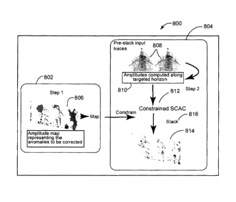
[0044] Looking to Figure 8 and a further variant of an embodiment 800, a
simplified flow using only a single constrained inversion 812 is depicted. The
embodiment 800 comprises two steps 802, 804 wherein an amplitude map 806 is
constructed in a first step 802 and a constrained surface consistent amplitude
correction computation 812 is performed in a second step 804. It should be
noted
in the embodiment 800 that any amplitude map 806 accurately representing the
amplitude anomalies to be corrected on the target horizon can be used in the
embodiment 800.
[0045] Looking to Figure 8 and a first step 802 of an embodiment 800, an
amplitude map 806 is constructed by dividing a constant factor, e.g., 1, by an
amplitude map representing the amplitude anomalies to be corrected. It should
be
CA 02839241 2014-01-14
CG200066
noted in the embodiment 800 that the amplitude map 806 computation can be
represented by the equation:
BAmp(k) = 1 / MAPAmp(k) (18)
wherein MAPAmp(k) is an amplitude map accurately representing the amplitude
anomalies to be corrected.
[0046] Continuing with a second step 804 of an embodiment 800, a
constrained surface consistent amplitude correction computation 812 is
performed.
The second step 804 of the embodiment 800 comprises designing a time window
around the targeted time interval 810 of the associated pre-stack seismic
traces
808. For example, the computation of TAmp(i, j) comprises the amplitude of
input
trace t(i, j) 808 around the target horizon corresponding to receiver "i" and
source
"j." Continuing with aspects of the second step 804 of the embodiment, the
surface
consistent general equations are resolved using three terms, i.e., a receiver
term, a
source term and a bin term. It should be noted in the embodiment that the
receiver
term and the source term are resolved but the bin term is not resolved but is
extracted from the amplitude map created in the previous step. For example,
the
source/receiver/bin surface consistent model, with fixed bin values is
represented
as:
TAmp(i, j) = RAMP(i) SAmp(j) BAmp(k) (19)
where Bp(k) = 1 / MAPAmp(k) and the surface consistent inversion provides the
computation of RAMP(i) and SAmp(j). Continuing with the second step 804 of the
embodiment 800, the surface consistent source and receiver scalars are applied
to
the input seismic traces 808, e.g., the computed scalars RAMP(i) and SAmp(j)
are
used in the equation:
tCORRECTION(i, j) = t(i, j) / (RAmpW SAMPW) (20)
to generate a stack of corrected trace data 816.
16
CA 02839241 2014-01-14
CG200066
[0047] Looking now to Figure 9 and another variant of an embodiment 900,
a constrained surface consistent amplitude correction inversion for a four-
dimensional (4D) seismic dataset is depicted. A first step 902 of an
embodiment
900 comprises selecting a time interval 910 on a dataset of seismic base data
912,
i.e., identifying initial amplitudes 918, and generating a reference amplitude
map
914 based on performing a surface consistent amplitude correction 916 of the
initial
amplitudes 918 of the seismic base data 912 and applying the surface
consistent
base source and receiver scalars to the seismic base data 912 to generate a
base
stack of corrected seismic base trace data 936. Continuing with a second step
904
of the embodiment 900, comprises selecting a time interval 920 on a dataset of
seismic monitor data 922, i.e., identifying initial amplitudes 924, and
generating a
first amplitude map 926 based on performing a surface consistent amplitude
correction 928 of the initial amplitudes 924 of the seismic monitor data 922
and
applying the surface consistent monitor source and receiver scalars to the
seismic
monitor data 922 to generate a monitor stack of corrected seismic monitor
trace
data 938.
[0048] Looking now to a third step 906 of the embodiment 900, the
reference
amplitude map 914 and the first amplitude map 926 are used to compute a
combined amplitude map 930 by dividing the reference amplitude map 914 by the
first amplitude map 926. Continuing with a fourth step 908 of the embodiment
900,
a constrained surface consistent amplitude correction 932 is performed on the
initial
amplitudes 924 of the seismic monitor data 922 to generate a second amplitude
map 934 based on applying corrections associated with the combined amplitude
map 930 by applying the surface consistent constrained source and receiver
scalars to the seismic monitor data 922 to generate a second stack of
corrected
seismic monitor trace data 940. It should be noted in the previously described
embodiments and variants of embodiments that pre-conditioning on the input
map,
comprising smoothing, filtering, editing, interpolation and extrapolation data
can be
performed. It should further be noted that the embodiments can be extended to
17
CA 02839241 2014-01-14
CG200066
any surface consistent attribute that can be decomposed into the same surface
consistent model.
[0049] Looking now to Figures 10A, 10B, 10C, 10D and 10E, a series of
seismic images illustrate the advantages of the application of an embodiment.
Beginning with Figure 10A, a seismic image depiction of raw amplitude along a
horizon where reflection coefficient variations are known to be small, i.e.,
plus or
minus twenty-five percent. Next, Figure 10B depicts a reflectivity map,
extracted
from well logs. Looking now to Figure 10C, an embodiment constrained inversion
has been applied and the seismic image shows that the amplitude variability of
the
depicted horizon is dramatically reduced. It should be noted in the embodiment
application that the background variation is directly relative to the
reflectivity
variation from the well log data, while high frequency variations are relative
to
geological features such as, but not limited to, faults. Turning now to Figure
10D,
depicted are the low frequency components of the post inversion amplitude map
of
Figure 10C and it is illustrated that the low frequency filtered map matches
the
reflectivity map of Figure 10B. Looking to Figure 10E, benefits of the
embodiments
are illustrated wherein the long wavelengths that appear on the initial
dataset 1002
have successfully been removed after performing data-constrained surface
consistent amplitude correction 1004 without removing the high frequency
amplitude variations related to geology.
[0050] Looking now to Figure 11, a method embodiment 1100 of
constraining wavelength components of a surface consistent inversion
associated with a surface consistent amplitude correction of seismic trace
data is
depicted. Starting at step 1102, the method embodiment 1100 computes a first
surface consistent amplitude correction flow based on a predetermined time
window. It should be noted in the embodiment that the time window brackets a
predetermined target. Further in embodiment step 1102, a first set of surface
consistent source and receiver scalars are generated. Looking next to step
1104
18
CA 02839241 2014-01-14
CG200066
of the method embodiment 1100, a first stack of corrected trace data are
generated after applying the first set of surface consistent source and
receiver
scalars to the seismic trace data.
[0051] Continuing at step 1106 of the method embodiment 1100, a first
amplitude map is generated for constraining a second surface consistent
amplitude correction. It should be noted in the method embodiment 1100 that
the
first amplitude map is associated with the predetermined time window and based
on the first stack of corrected trace data. Next at step 1108 of the method
embodiment 1100, a second surface consistent amplitude correction flow is
computed. It should be noted in the embodiment 1100 that the second surface
consistent amplitude correction flow is based on the time window, the first
amplitude map and a bin term. Further, the step 1108 generates a second set of
source and receiver scalars. Next at step 1110 of the method embodiment 1100,
a second stack of corrected stack trace data is generated by applying the
second
set of surface consistent source and receiver scalars to the seismic trace
data.
[0052] Looking now to Figure 12, another method embodiment 1200 of
constraining wavelength components of a surface consistent inversion
associated with a surface consistent amplitude correction of seismic trace
data is
depicted. Starting at step 1202, the method embodiment 1200 generates an
amplitude map, associated with a predetermined time window and based on
accurately representing amplitude anomalies, for constraining a surface
consistent amplitude correction.
[0053] Next, at step 1204 of the method embodiment 1200, a surface
consistent amplitude correction flow is computed and a set of surface
consistent
source and receiver scalars are generated. It should be noted in the method
embodiment 1200 that the computation is based on the time window, the
amplitude map and a bin term.
19
CA 02839241 2014-01-14
CG200066
[0054] Looking now to Figure 13, another method embodiment 1300 of
constraining wavelength components of a surface consistent inversion
associated with a surface consistent amplitude correction of seismic trace
data is
depicted. Beginning with step 1302 of the method embodiment 1300, a surface
consistent amplitude correction flow is computed for a seismic base trace
dataset. It should be noted in the method embodiment 1300 that the surface
consistent amplitude correction computation is based on a predetermined time
window and generates a set of surface consistent source and receiver scalars
based on the seismic base trace dataset.
[0055] Next at step 1304 of the method embodiment 1300, a base stack of
corrected seismic base trace data is generated by applying the previously
generated base surface consistent source and receiver scalars to the seismic
base trace data. Continuing with step 1306 of the method embodiment 1300, a
base amplitude map is generated based on the previously generated stack of
corrected seismic base trace data. It should be noted in the method embodiment
1300 that the base amplitude map is associated with the predetermined time
window.
[0056] Continuing with step 1308 of the method embodiment 1300, a
second surface consistent amplitude correction flow computation is performed
on
a second seismic trace dataset of seismic monitor trace data. It should be
noted
in the method embodiment 1300 that the monitor surface consistent amplitude
correction flow is also based on the predetermined time window and generates a
monitor set of surface consistent source and receiver scalars. Next at step
1310
of the method embodiment 1300, a monitor stack of corrected seismic monitor
trace data is generated by applying the previously generated monitor surface
consistent source and receiver scalars to the seismic monitor trace data.
[0057] Continuing with step 1312 of the method embodiment 1300, a
monitor amplitude map is generated based on the previously generated stack of
CA 02839241 2014-01-14
CG200066
corrected seismic monitor trace data. It should be noted in the method
embodiment 1300 that the monitor amplitude map is associated with the
predetermined time window.
[0058] Next at step 1314 of the method embodiment 1300, a combined
amplitude map is generated based on combining the base amplitude map and
the monitor amplitude map. It should be noted in the method embodiment 1300
that the combined amplitude map is used to adjust the amplitude differences
between the two different vintages of amplitude maps.
[0059] Continuing with step 1316 of the method embodiment 1300, a 4D
surface consistent amplitude correction flow is computed on the seismic
monitor
data. It should be noted in the method embodiment 1300 that 4D surface
consistent amplitude correction flow computation is constrained by the
combined
amplitude map and a bin term. It should further be noted in the method
embodiment 1300 that the combined amplitude map is associated with the
predetermined time window and generates a set of 4D surface consistent source
and receiver scalars.
[0060] Looking now to Figure 14, a schematic diagram of an embodiment
node 1400 for generating a corrected amplitude map based on constraining
wavelength components of a surface consistent inversion is depicted. The
embodiment node 1400 comprises a time interval component 1402, a surface
consistent scalar component 1404, an amplitude map component 1406, an engine
component 1408, an output component 1410 and one or more seismic trace
datasets 1412. Continuing with the embodiment node, the time interval
component
1402 provides the ability to design a computational time window around a
portion of
the applicable datasets.
[0061] Next in the embodiment node 1400, the surface consistent scalar
component 1404 provides the ability to calculate surface consistent source and
21
CA 02839241 2014-01-14
CG200066
receiver scalars based on a surface consistent amplitude correction
computation
associated with one or more seismic trace datasets. Continuing with the
embodiment node 1400, the amplitude map component provides the capability to
generate amplitude maps based on the previously determined surface consistent
source and receiver scalars and one or more of the seismic trace datasets. It
should be noted in the embodiment node 1400 that amplitude maps can also be
generated based on combining previously generated amplitude maps.
[0062] Continuing with the embodiment node 1400, an engine component
1408 provides the capability to apply the amplitude maps to the seismic trace
datasets. It should be noted in the embodiment node 1400 that the amplitude
maps
can be generated based on computations associated with the seismic trace
datasets or the amplitude maps can be constructed from data representing the
anomalies to be corrected. It should further be noted in the embodiment node
1400
that the engine component provides access to the seismic trace datasets.
[0063] Next in the embodiment node 1400, the output component 1410
provides the capability to output a corrected amplitude map. It should be
noted in
the embodiment node 1400 that the output component can also output stacks of
corrected trace data and sets of surface consistent source and receiver
scalars.
[0064] The computing device(s) or other network nodes involved in ghost
compensated modeled seismic image prediction as set forth in the above
described embodiments may be any type of computing device capable of
processing and communicating seismic data associated with a seismic survey.
An example of a representative computing system capable of carrying out
operations in accordance with these embodiments is illustrated in Figure 15.
System 1500 includes, among other items, server 201, source/receiver interface
1502, internal data/communications bus (bus) 204, processor(s) 208 (those of
ordinary skill in the art can appreciate that in modern server systems,
parallel
processing is becoming increasingly prevalent, and whereas a single processor
22
CA 02839241 2014-01-14
CG200066
would have been used in the past to implement many or at least several
functions, it is more common currently to have a single dedicated processor
for
certain functions (e.g., digital signal processors) and therefore could be
several
processors, acting in serial and/or parallel, as required by the specific
application), universal serial bus (USB) port 210, compact disk (CD)/digital
video
disk (DVD) read/write (RNV) drive 212, floppy diskette drive 214 (though less
used currently, many servers still include this device), and data storage unit
232.
[0065] Data storage unit 232 itself can comprise hard disk drive (HDD)
216
(these can include conventional magnetic storage media, but, as is becoming
increasingly more prevalent, can include flash drive-type mass storage devices
224, among other types), ROM device(s) 218 (these can include electrically
erasable (EE) programmable ROM (EEPROM) devices, ultra-violet erasable
PROM devices (UVPROMs), among other types), and random access memory
(RAM) devices 220. Usable with USB port 210 is flash drive device 224, and
usable with CD/DVD R/VV device 212 are CD/DVD disks 234 (which can be both
read and write-able). Usable with diskette drive device 214 are floppy
diskettes
237. Each of the memory storage devices, or the memory storage media (216,
218, 220, 224, 234, and 237, among other types), can contain parts or
components, or in its entirety, executable software programming code
(software)
236 that can implement part or all of the portions of the method described
herein.
Further, processor 208 itself can contain one or different types of memory
storage devices (most probably, but not in a limiting manner, RAM memory
storage media 220) that can store all or some of the components of software
236.
[0066] In addition to the above described components, system 200 also
comprises user console 234, which can include keyboard 228, display 226, and
mouse 230. All of these components are known to those of ordinary skill in the
art, and this description includes all known and future variants of these
types of
devices. Display 226 can be any type of known display or presentation screen,
23
CA 02839241 2014-01-14
CG200066
such as liquid crystal displays (LCDs), light emitting diode displays (LEDs),
plasma displays, cathode ray tubes (CRTs), among others. User console 235
can include one or more user interface mechanisms such as a mouse, keyboard,
microphone, touch pad, touch screen, voice-recognition system, among other
inter-active inter-communicative devices.
[0067] User
console 234, and its components if separately provided,
interface with server 201 via server input/output (I/0) interface 222, which
can be
an RS232, Ethernet, USB or other type of communications port, or can include
all
or some of these, and further includes any other type of communications means,
presently known or further developed. System
200 can further include
communications satellite/global positioning system (GPS) transceiver device
238,
to which is electrically connected at least one antenna 240 (according to an
exemplary embodiment, there would be at least one GPS receive-only antenna,
and at least one separate satellite bi-directional communications antenna).
System 200 can access internet 242, either through a hard wired connection,
via
I/0 interface 222 directly, or wirelessly via antenna 240, and transceiver
238.
[0068] Server
201 can be coupled to other computing devices, such as
those that operate or control the equipment of ship 2, via one or more
networks.
Server 201 may be part of a larger network configuration as in a global area
network (GAN) (e.g., internet 242), which ultimately allows connection to
various
landlines.
[0069]
According to a further exemplary embodiment, system 200, being
designed for use in seismic exploration, will interface with one or more
sources
4a,b and one or more receivers 14. These, as previously described, are
attached
to streamers 6a,b, to which are also attached birds 13a,b that are useful to
maintain positioning. As further previously discussed, sources 4 and receivers
14 can communicate with server 201 either through an electrical cable that is
part
24
CA 02839241 2014-01-14
CG200066
of streamer 6, or via a wireless system that can communicate via antenna 240
and transceiver 238 (collectively described as communications conduit 246).
[0070]
According to further exemplary embodiments, user console 235
provides a means for personnel to enter commands and configuration into
system 200 (e.g., via a keyboard, buttons, switches, touch screen and/or joy
stick). Display device 226 can be used to show: streamer 6 position; visual
representations of acquired data; source 4 and receiver 14 status information;
survey information; and other information important to the seismic data
acquisition process. Source and receiver interface unit 202 can receive the
hydrophone seismic data from receiver 14 though streamer communication
conduit 248 (discussed above) that can be part of streamer 6, as well as
streamer 6 position information from birds 13; the link is bi-directional so
that
commands can also be sent to birds 13 to maintain proper streamer positioning.
Source and receiver interface unit 202 can also communicate bi-directionally
with
sources 4 through the streamer communication conduit 248 that can be part of
streamer 6.
Excitation signals, control signals, output signals and status
information related to source 4 can be exchanged by streamer communication
conduit 248 between system 200 and source 4.
[0071] Bus
204 allows a data pathway for items such as: the transfer and
storage of data that originate from either the source sensors or streamer
receivers; for processor 208 to access stored data contained in data storage
unit
memory 232; for processor 208 to send information for visual display to
display
226; or for the user to send commands to system operating programs/software
236 that might reside in either the processor 208 or the source and receiver
interface unit 202.
[0072] System
200 can be used to implement the methods described
above associated with ghost compensated modeled seismic image prediction
according to an exemplary embodiment. Hardware, firmware, software or a
CA 02839241 2014-01-14
CG200066
combination thereof may be used to perform the various steps and operations
described herein. According to an exemplary embodiment, software 236 for
carrying out the above discussed steps can be stored and distributed on multi-
media storage devices such as devices 216, 218, 220, 224, 234, and/or 237
(described above) or other form of media capable of portably storing
information
(e.g., universal serial bus (USB) flash drive 426). These storage media may be
inserted into, and read by, devices such as the CD-ROM drive 414, the disk
drive
412, among other types of software storage devices.
[0073] The disclosed exemplary embodiments provide a server node, and a
method for ghost compensated modeled seismic image prediction associated with
seismic depth images. It should be understood that this description is not
intended
to limit the invention. On the contrary, the exemplary embodiments are
intended to
cover alternatives, modifications and equivalents, which are included in the
spirit
and scope of the invention. Further, in the detailed description of the
exemplary
embodiments, numerous specific details are set forth in order to provide a
comprehensive understanding of the invention. However, one skilled in the art
would understand that various embodiments may be practiced without such
specific
details.
[0074] Although the features and elements of the present exemplary
embodiments are described in the embodiments in particular combinations, each
feature or element can be used alone without the other features and elements
of
the embodiments or in various combinations with or without other features and
elements disclosed herein. The methods or flow charts provided in the present
application may be implemented in a computer program, software, or firmware
tangibly embodied in a computer-readable storage medium for execution by a
general purpose computer or a processor.
[0075] This written description uses examples of the subject matter
disclosed to enable any person skilled in the art to practice the same,
including
26
CA 02839241 2014-01-14
CG200066
making and using any devices or systems and performing any incorporated
methods. The patentable scope of the subject matter is defined by the claims,
and
may include other examples that occur to those skilled in the art. Such other
examples are intended to be within the scope of the claims.
27