Note: Descriptions are shown in the official language in which they were submitted.
CA 02839291 2013-12-12
WO 2013/006624 PCT/US2012/045412
WIRELESS MONITORING SYSTEMS FOR USE WITH PRESSURE SAFETY
DEVICES
FIELD OF THE DISCLOSURE
[0001] This patent relates to pressure safety devices and, more specifically,
to wireless
monitoring systems for use with pressure safety devices.
BACKGROUND
[0002] Process control systems use a variety of field devices to control
and/or monitor
process parameters. For example, pressure of a fluid in a containment vessel
is a parameter
that is typically monitored in a process control system. Pressure relief
valves and rupture
disks are often employed as safety devices to prevent over pressurization or
under
pressurization of a fluid (e.g., a liquid, a gas, fluid power) in a
containment vessel. For
example, a pressure relief valve enables pressure within the containment
vessel to be relieved
when an operating pressure of a fluid within the containment vessel exceeds a
pressure rating
of the pressure relief valve. A rupture disk is a sensor that provides a
signal or indication that
pressure is being relieved from the containment vessel (e.g., via the pressure
relief valve,
directly to atmosphere via the rupture disk, etc.).
[0003] Monitoring devices are often hardwired to a control system. However,
hardwiring a
monitoring device to a control system significantly increases costs.
Additionally, monitoring
devices used in hazardous conditions or areas require intrinsically safe (IS)
power modules or
panels that provide power to a sensor of the monitoring device. The panel is
then hardwired
to a control system located in a non-hazardous area. Such a configuration
significantly
increases costs.
SUMMARY
[0004] An example wireless monitoring system includes a field device and a
wireless
transceiver coupled to the field device to receive a signal generated by the
field device. The
wireless transceiver has a self-contained power module. A wireless interface
is
communicatively coupled to the wireless transceiver without an interposing
intrinsically safe
barrier panel. The wireless interface wirelessly receives the signal from the
wireless
transceiver.
[0005] An example method for monitoring a system includes monitoring a fluid
characteristic of a process fluid via a field device and communicatively
coupling the field
- 1 -
CA 02839291 2013-12-12
WO 2013/006624 PCT/US2012/045412
device to a wireless transceiver that provides an intrinsically safe
certification for use in a
hazardous location. The method also includes sending a signal generated by the
field device
to a wireless interface via the wireless transceiver without the use of an
intrinsically safe
barrier.
[0006] An example wireless field device assembly includes a field device
having a sensor to
monitor a fluid parameter of a process fluid. The sensor generates an
electrical signal when
the fluid parameter is greater than or less than a pre-set value. A wireless
transceiver is
coupled to the field device and has a self-contained power module to provide
an intrinsically
safe certification for use in a hazardous condition. The wireless transceiver
has a first
discrete input to receive the electrical signal generated by the sensor of the
field device and
the wireless transceiver communicates the received electrical signal to a
wireless interface
without an interposing intrinsically safe panel.
BRIEF DESCRIPTION OF THE DRAWINGS
[0007] FIG. 1 depicts a known monitoring system.
[0008] FIG. 2 depicts a block diagram of an example wireless monitoring system
in
accordance with the teachings disclosed herein.
[0009] FIG. 3 depicts an example wireless monitoring system described herein.
[0010] FIG. 4 depicts a flowchart of an example method for implementing an
example
wireless monitoring system disclosed herein.
DETAILED DESCRIPTION
[0011] The examples described herein relate to methods and apparatus for
wirelessly
monitoring pressure safety devices of a process system. More specifically, an
example
wireless monitoring system described herein employs an intrinsically safe,
powered wireless
interface or transmitter (e.g., a transceiver) that can be coupled to a sensor
of a monitoring
device for use in hazardous conditions or environments. As a result, an
example wireless
monitoring system described herein eliminates the need for wiring a sensor to
an intrinsically
safe panel that is interposed between, for example, a control room and the
sensor of the
pressure safety device. Intrinsically safe (IS) is a protection certification
for safe operation of
a device with electronic equipment in hazardous areas such as, for example,
explosive or
volatile atmospheres in the petrochemical industry. A device termed
"intrinsically safe" is
designed and certified to eliminate or encapsulate any components that produce
sparks or
- 2 -
CA 02839291 2013-12-12
WO 2013/006624 PCT/US2012/045412
which could generate enough heat to cause an ignition in areas with flammable
gasses, dusts
or fuels, etc.
[0012] An example monitoring system described herein includes a sensor to
monitor a fluid
characteristic or parameter of a fluid (e.g. a pressure of the fluid) coupled
to a wireless
interface or transmitter or transceiver. The wireless transmitter or
transceiver may be coupled
directly to the sensor and/or may be coupled remotely relative to the sensor.
For example, the
sensor generates an electrical signal when a fluid parameter sensed by the
sensor is greater
than or less than (e.g., outside a desired range) a pre-set or predetermined
parameter value.
The wireless transmitter broadcasts and/or communicates the signal generated
by the sensor
to a gateway, which configures the signal received from the wireless
transmitter and sends
the configured signal to a control system or monitoring device via, for
example, one or more
data busses (Ethernet, Modbus, etc.). In particular, the wireless transmitter
provides an
intrinsically safe power module that communicates wireless signals to a
wireless interface of
a control system without the need for an intrinsically safe panel. The example
wireless
transmitter disclosed herein provides an intrinsically safe certification for
use in hazardous
locations or areas. Thus, the example monitoring systems described herein
eliminate the
need for hardwiring a sensor to an intrinsically safe barrier or panel.
Additionally, the
example monitoring system described herein includes wireless field device
interfaces that
eliminate the need for and the costs associated with an intrinsically safe
barrier or panel.
Further, the wireless interface or gateway allows the wireless transmitter to
communicate via
OPC, Modbus, Ethernet or serial 485 without discrete input cards.
[0013] FIG. 1 illustrates a known monitoring system 100 for use with a process
system 102
in a hazardous environment 104. More specifically, the monitoring system 100
is
implemented with a hardwired communication network 106. In general,
communication
channels, links and paths that enable the monitoring system 100 to function
within the
process system 102 are commonly collectively referred to as a communication
network. As
shown in FIG.1, the monitoring system 100 includes a sensor 108 (e.g., a burst
sensor)
coupled to a tank or pressure-vessel 110 to sense a pressure of a fluid (e.g.,
liquid, gas, etc.)
within the tank 110. In hazardous applications (e.g., petrochemical industry,
refining
industry, power industry, pulp & paper, etc.), the sensor 108 is powered via
an intrinsically
safe terminal barrier panel 112. The barrier panel 112 provides a protection
certification for
safe operation with electronic equipment in hazardous (e.g., explosive)
atmospheres or
conditions. As shown in FIG. 1, the sensor 108 is connected to the barrier
panel 112 via
wires 114. In turn, the barrier panel 112 is communicatively coupled via wires
116 and 118
- 3 -
CA 02839291 2013-12-12
WO 2013/006624 PCT/US2012/045412
to an alarm 120 and/or a controller 122 located remotely from the sensor 108.
For example,
the alarm 120 and/or the controller 122 are located in a non-hazardous
location 124 (e.g., a
control room of a process plant). Thus, the monitoring system 100 requires
running wires
and conduit from the sensor 108 to the barrier panel 112 and from the barrier
panel 112 to the
controller 122 (e.g., a control room) when the monitoring system 100 is used
in a hazardous
application.
[0014] However, hardwired communication networks are typically expensive to
install,
particularly in cases where the communication network 106 is associated with a
large
industrial plant or facility that is distributed over a relatively large area
and/or tanks having
relatively large heights. In many instances, the wiring associated with the
communication
network 106 may have to span relatively long distances and/or through, under
or around
many structures (e.g., walls, buildings, equipment, etc.) Such long wiring
runs typically
involve substantial amounts of labor and, thus, expense. Further, such long
wiring runs are
especially susceptible to signal degradation due to wiring impedances and
coupled electrical
interference, both of which can result in unreliable communications.
[0015] In some examples, known wireless communication networks, including the
hardware
and software associated therewith, provide point-to-point or direct
communication paths that
are selected during installation and fixed during subsequent operation of the
system.
Establishing fixed communication paths within these known wireless
communication
networks typically involves the use of one or more experts to perform an
expensive site
survey that enables the experts to determine the types and/or locations of
transceivers and
other communication equipment. Additionally, a signal provided by a point-to-
point
communication path may be blocked or degraded and, thus, may not be
effectively
communicated to a receiver or controller, thereby reducing the accuracy and
reliability of a
monitoring system. Further, such known wireless communication networks often
lack an
intrinsically safe wireless device and, thus, often require the use of the
intrinsically safe
terminal barrier panel 112 to provide power and/or communication with a field
device or
sensor used in a hazardous condition or application.
[0016] FIG. 2 illustrates a block diaphragm of a portion of a process control
system 200
having an example wireless communication network 202 described herein. As
shown in FIG.
2, the portion of the process control system 200 includes a plurality of
wireless field devices
204 and 206. Each of the wireless field devices 204 and 206 includes
respective field devices
or sensors 208 and 210 and wireless field device interfaces 212 and 214 (e.g.,
wireless
transceivers). The wireless field device interfaces 212 and 214 broadcast or
communicate
- 4 -
CA 02839291 2013-12-12
WO 2013/006624 PCT/US2012/045412
signals generated by the respective field devices 208 and 210 (e.g., sensors).
In general, the
wireless field device interfaces 212 and 214 are communicatively coupled to a
control system
216 via at least one wireless interface 218 (e.g., a gateway). The wireless
interface 218 may
serve as a communication hub. The wireless interface 218 may be
communicatively coupled
to the control system 216 via, for example, an Ethernet connection 220, a
Modbus Ethernet
connection 222, a serial R485 connection 224 and/or any other suitable
connection(s). The
wireless interface 218 may also support or make use of communication standards
and
protocols such as, for example, a local interface 226, a serial modbus 228, a
remote interface
230, Modbus TCP/IP 232, Delta V or AMS 234, OPC 236 and/or any other suitable
communication standard(s) or protocol(s).
[0017] The wireless field device 204 may be a non-smart type field device
(e.g., a sensor)
that is to perform wireless communications with other similarly enabled
wireless field
devices such as the wireless field device 210 and/or one or more wireless
interfaces such as
the wireless interface 218. Specifically, each of the wireless field devices
204 and 206 may
be configured to communicate via one or more wireless communication channels,
paths or
links 238, 240 and 242. Thus, each of the wireless field devices 204 and 206
may
communicate with the wireless interface 218 via multiple or redundant
communication paths
238, 240 and 242. In general, the wireless field device interfaces 212 and 214
of the
respective field devices 208 and 210 may be used to form one or more wireless
field nodes
244 of a mesh network. Such wireless field nodes 244 may be remotely located
from the
control system 216. For example, the first wireless field device interface 212
may be a first
field node and the second wireless field device interface 214 may be a second
field node of
the mesh network. Each of the wireless field device interfaces 212 and 214 may
include
wireless communication interface circuitry to transmit a signal generated by
the respective
field devices 208 and 210 and/or receive a signal from the control system 216
via the wireless
interface 218. The wireless field device interfaces 212 and/or 214 may
communicate via
radio signals and/or any desired wireless communication standard or protocol
via an antenna
246.
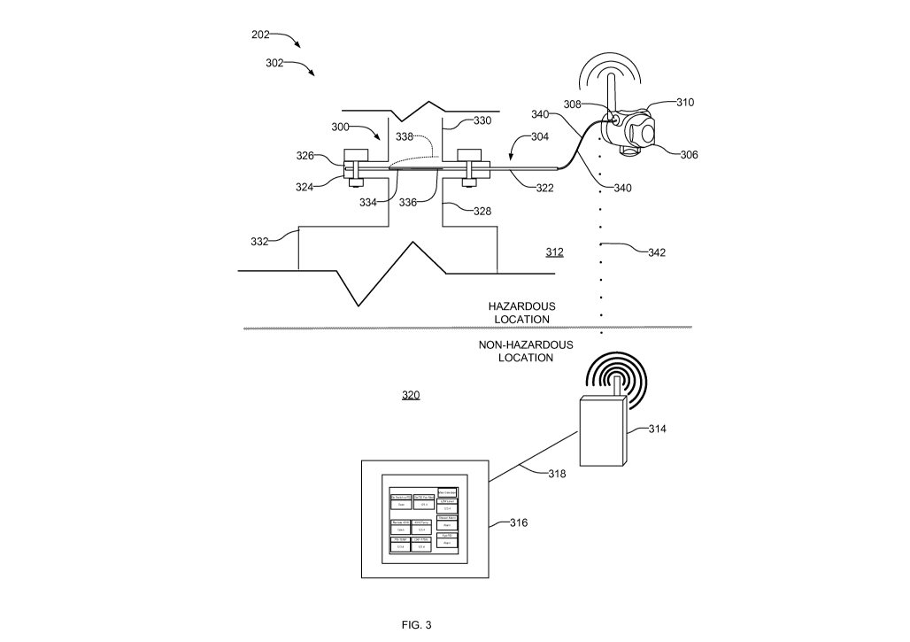
[0018] FIG. 3 depicts a portion of the example wireless communication network
202 of FIG.
2 implemented with a wireless field device or monitoring system 300 of a
process control
system 302 having hazardous process fluids. The wireless monitoring system 300
of FIG. 3
includes a field device 304 coupled to a wireless field device interface or
wireless transceiver
306 via a first discrete input 308 (e.g., a simple switch or dry contact
input). The wireless
transceiver 306 may also include a plurality of discrete inputs to receive a
plurality of field
- 5 -
CA 02839291 2013-12-12
WO 2013/006624 PCT/US2012/045412
devices. In the example shown, the wireless transceiver 306 includes a second
input 310 to
receive a second field device (not shown).
[0019] As shown in FIG. 3, the wireless monitoring system 300 is disposed in a
hazardous
location or area 312. In addition, the wireless transceiver 306 provides
intrinsically safe
certification for use in hazardous conditions. The wireless transceiver 306 is
a self-powered
transmitter that has a self-contained power module (e.g., a battery pack). For
example, the
wireless transceiver 306 may be a Rosemount 702 wireless transmitter
manufactured by
Rosemount, Inc. Unlike the known hardwired monitoring system 100 of FIG. 1 or
known
wireless networks, the wireless monitoring system 300 does not require use of
an intrinsically
safe barrier panel (e.g., the barrier panel 112 of FIG. 1).
[0020] The wireless transceiver 306 is communicatively coupled to a wireless
interface or
gateway 314. The gateway 314 is coupled to a control system 316 (e.g., a host
system, a
controller, an alarm, or other system) via a connection 318. For example, the
control system
316 may be in a control room located in a non-hazardous location 320.
Additionally, similar
to the wireless field devices 204 and 206 of FIG. 2, the wireless monitoring
system 300 may
be a node of a mesh network (e.g., a full or partial mesh topology) and may
simultaneously
communicate with other wireless enabled field devices and/or wireless
interfaces within the
process system 302.
[0021] The field device 304 of the illustrated example is a burst sensor 322.
The burst sensor
322 is coupled between flanges 324 and 326 of respective pipes 328 and 330.
The burst
sensor 322 senses or monitors a pressure of a fluid (e.g., a fluid parameter
or characteristic)
within a tank or fluid containment vessel 332. The burst sensor 322 includes a
filament 334
that moves from a connected or engaged position 336 to a disengaged or
ruptured position
338 (shown in dashed lines) when a pressure within the tank 332 is greater
than a desired set
point pressure (e.g., a pre-set parameter or value). Thus, the burst sensor
322 provides a
switch sensor (not shown) that is electrically coupled to the discrete input
308 of the wireless
transmitter 306 via wires 340. The physical connections may provide screw
terminals,
pluggable connections (e.g., a female or male header), insulation displacement
connections
and/or any other desired type of electrical connector(s). For example, the
Rosemount 702
wireless transmitter can accept input from one or two single pole, single
throw switches via
the respective first and second discrete inputs. In other examples, the burst
sensor 322 and the
wireless transmitter 306 may be a unitary structure. Once coupled to the field
device 304, a
tag or network I.D. representative of the wireless transmitter 306 is assigned
in an operator
- 6 -
CA 02839291 2013-12-12
WO 2013/006624 PCT/US2012/045412
interface or the control system 316 via the gateway 314 so that the particular
field device 304
or burst sensor 322 may be monitored via the control system 316.
[0022] In operation, when the burst sensor 322 is in the connected position
336, a circuit is
complete or closed. A closed circuit or switch generates a logical true output
signal. The
wireless transmitter 306 broadcasts a logical true output signal to the
gateway 314 via a
wireless communication path 342 and/or other wireless enabled field devices in
the process
system 302. The gateway 314, in turn, communicates the same to the control
system 316.
When the burst sensor 322 is in the ruptured position 338 (e.g., when the
pressure within the
tank 332 is greater than the rupture rating of the burst sensor 322), the
circuit is incomplete or
open. An open circuit or switch drives a logical false output signal. The
wireless transceiver
306 broadcasts and/or communicates the false output signal (e.g., the open and
closed
signals) to the gateway 314 via the wireless communication path 342. In turn,
the gateway
314 communicates the signal to the control system 316, which may provide an
alarm or
indication to an operator that a rupture disk associated with the burst sensor
322 has ruptured.
For example, the wireless signals provided by the wireless transceiver 306 may
be monitored
via, for example, HARTTm or Modbus tags instead of discrete inputs. Although
not shown, in
other examples, the field device 304 or sensor may be coupled to safety relief
valves to detect
pressure or fluid releases.
[0023] FIG. 4 depicts a flow diagram of an example process 400 that may be
used to
implement the example wireless monitoring system disclosed herein. The example
process
400 begins by monitoring a fluid characteristic or parameter (e.g., a fluid
pressure) via a field
device (block 402). For example, the field device may monitor a pressure of a
fluid within a
fluid containment vessel and is configured to generate a signal when the fluid
characteristic
or parameter deviates from a pre-set value. (block 404). For example, the
field device may
include a sensor such as, for example, a burst sensor (e.g., the burst sensor
322 of FIG. 3)
having a filament that moves to a ruptured position when the pressure in the
fluid
containment vessel is greater than a pre-determined pressure value. Upon
detection of
filament moving to the ruptured position, the field device generates an
electrical signal.
[0024] A wireless transmitter or transceiver coupled to the field device
receives or detects
the generated signal (406). For example, the field device may be coupled to
the wireless
transceiver via wires. In this example, the wireless transmitter is powered
via a self-
contained power module to provide an intrinsically safe certification for use
in a hazardous
location and without the need for an intrinsically safe barrier.
- 7 -
CA 02839291 2013-12-12
WO 2013/006624 PCT/US2012/045412
[0025] In turn, the wireless transceiver broadcasts the generated signal
(block 408). For
example, the wireless transceiver is communicatively coupled to a wireless
interface and
wirelessly sends the generated signal to the wireless interface. For example,
the wireless
interface may be a gateway.
[0026] In some examples, a control system receives the generated signal from
the wireless
interface (block 410). For example, the wireless interface may be
communicatively coupled
to a control system to alert an operator in a control room of the generated
signal. In some
examples, the control system may be located in a non-hazardous location (e.g.,
a control
room) and the field device and the wireless transceiver may be located in a
hazardous
location.
[0027] Although certain example methods, apparatus and articles of manufacture
have been
described herein, the scope of coverage of this patent is not limited thereto.
On the contrary,
this patent covers all methods, apparatus and articles of manufacture fairly
falling within the
scope of the appended claims either literally or under the doctrine of
equivalents.
- 8 -