Note: Descriptions are shown in the official language in which they were submitted.
CA 02839333 2014-01-13
JET ENGINE NOZZLE EXIT CONFIGURATIONS AND ASSOCIATED
SYSTEMS AND METHODS
TECHNICAL FIELD
The present disclosure is directed to jet engine nozzle exit configurations
and associated systems and methods, including nozzles having chevrons or other
projections that vary in a circumferential or azimuthal manner around an exit
perimeter
of the nozzle.
BACKGROUND
Aircraft manufacturers are under continual pressure to reduce the noise
produced by aircraft in order to satisfy increasingly stringent noise
certification rules.
Aircraft engines are a major contributor to overall aircraft noise.
Accordingly, aircraft
engines in particular have been the target of manufacturers' noise reduction
efforts.
Aircraft engines have been made significantly quieter as a result of advanced
high
bypass ratio engines. These engines derive a significant fraction of their
total thrust not
directly from jet exhaust, but from bypass air which is propelled around the
core of the
engine by an engine-driven forwardly mounted fan. While this approach has
significantly reduced aircraft noise when compared with pure turbojet engines
and low
bypass ratio engines, engine and aircraft federal regulations nevertheless
continue to
require further engine noise reductions.
One approach to reducing engine noise is to increase the amount of
mixing between the high velocity gases exiting the engine, and the surrounding
freestream air. Figure 1 illustrates a nozzle 20 having "chevrons" that are
designed to
produce this effect. Chevrons generally include certain types of serrations on
the
nozzle lip, typically, triangular in shape having some curvature in the
lengthwise cross-
section, which slightly immerses them in the adjacent flow. The chevron can
project
either inwardly or outwardly, by an amount that is on the order of the
upstream
boundary layer thickness on the inner or outer surface, respectively. In
general, the
chevron planform shape can also be trapezoidal or rectangular. The nozzle 20
includes a core flow duct 40 through which the engine core flow is directed,
and a fan
-1-
CA 02839333 2015-07-23
flow duct 30 arranged annularly around the core flow duct 40, through which
the fan air
passes. The exit aperture of the fan flow duct 30 can include fan flow
chevrons 35, and
the exit aperture of the core flow duct 40 can include core flow chevrons 45.
The
chevrons typically reduce the low-frequency noise by increasing the rate at
which the
engine flow streams mix with the surrounding freestream air at the length
scale of the
nozzle diameter. While this approach has resulted in noise reduction compared
with
nozzles that do not include chevrons, further noise reduction is desired to
meet
community noise standards.
SUMMARY
The following summary is provided for the benefit of the reader only, and is
not
intended to limit in any way the invention as set forth by the claims.
Particular aspects of
the disclosure are directed to an aircraft system that includes a jet engine
exhaust nozzle
having an internal flow surface and an exit aperture. The exit aperture has a
perimeter
that includes multiple projections extending in an aft direction. The
projections can be
circumferentially spaced about the perimeter, and a geometric feature of the
multiple
projections can change in a monotonic manner along at least a portion of the
perimeter.
For example, successive projections can have a length that decreases in a
direction away
from a wing of the aircraft along the perimeter. In other aspects, the
geometric feature
can include an angular deflection of the projection, a shape of the
projection, and/or a
density of the projections around the perimeter. The manner in which the
geometric
feature is varied can reduce engine noise.
In further particular embodiments, the engine can include a turbofan engine,
and the exhaust nozzle can include a first internal flow surface positioned to
receive a fan
flow and a second internal flow surface positioned to receive an engine core
flow. Each
flow surface can terminate at an exit aperture, and each exit aperture can
include multiple
projections. A geometric feature of the projections at the fan flow internal
surface can
vary in a manner that is different from the manner in which the geometric
projections of
the core flow surface vary.
2
CA 02839333 2015-07-23
In still further particular embodiments, the manner in which the geometric
feature of the projections varies can depend upon the particular installation
of the nozzle.
For example, when the nozzle is positioned near an aircraft wing, the
projections can be
longer at the portion of the nozzle close to the wing, and shorter at the
portion of the
nozzle distant from the wing. When the nozzle is positioned proximate to an
aircraft
fuselage, the projections can be longer toward the fuselage and shorter at a
portion of the
nozzle positioned away from the fuselage. The variation of the projection
geometric
feature can be selected to reduce the acoustic signature on the ground and/or
in the
aircraft cabin.
Other aspects of the disclosure are directed to methods for manufacturing an
aircraft.
One method includes selecting a fuselage configuration and a wing
configuration. The method can further include selecting a turbofan nozzle
configuration to
include a fan flow duct having a first internal surface positioned to receive
a fan flow, and
a core flow duct having a second internal flow surface positioned to receive
an engine
core flow. The method can still further include selecting an exit aperture of
at least one of
the ducts to have a perimeter that includes multiple projections extending in
an aft
direction, with a portion of individual neighboring projections spaced apart
from each
other by a gap. A geometric feature of at least some of the projections is
selected in a
manner that depends at least in part on a location of the engine nozzle
relative to the
fuselage, the wing, or both the fuselage and the wing.
Another aspect is directed to a method for controlling aircraft noise and
includes directing gas through a jet engine nozzle and controlling a total
thrust vector of
the gas to be non-parallel to an acoustic intensity vector at one or more
acoustic
frequencies. The vectors are controlled by directing the gas adjacent to
multiple nozzle
projections having different geometric features, and mixing the gas with
adjacent
freestream air at the nozzle projections.
In one embodiment there is provided an aircraft system including a jet engine
exhaust nozzle including a turbofan nozzle. The turbofan nozzle includes a
first internal
flow surface positioned to receive a fan flow and a first exit aperture having
a first
perimeter including multiple projections extending in an aft direction and
circumferentially
spaced about the first perimeter with a geometric feature of the multiple
first projections
3
CA 02839333 2015-07-23
changing in a first manner along a portion of the first perimeter in a
monotonic manner
along a portion of the perimeter. The system further includes a second
internal flow
surface positioned to receive an engine core flow, the second flow surface
terminating at
a second exit aperture, the second exit aperture having a second perimeter,
the second
perimeter including multiple second projections extending in an aft direction,
with an aft
portion of individual neighboring second projections spaced apart from each
other by a
gap, and with a geometric feature of the multiple second projections varying
in a second
manner different than the first manner along a portion of the second
perimeter. The first
projections decrease in length around the first perimeter from a 12:00
position at the first
perimeter to a 6:00 position at the first perimeter. The second projections
increase in
length around the second perimeter from a 12:00 position at the second
perimeter to a
6:00 position at the second perimeter. The first internal flow surface
includes a portion of
a fan flow duct having a varying flow area with a convergent section, a
divergent section
downstream of the convergent section and a throat between the convergent and
divergent sections, with gaps between neighboring first projections
originating
downstream of the fan duct throat.
In another embodiment, there is provided an aircraft system. The system
includes a turbofan engine exhaust nozzle that includes a first internal flow
surface
positioned to receive a fan flow, the first flow surface terminating at a
first exit aperture,
the first exit aperture having a first perimeter, the first perimeter
including multiple first
projections extending in an aft direction, with an aft portion of individual
neighboring first
projections spaced apart from each other by a gap, and with a geometric
feature of the
multiple first projections varying in a first manner along a portion of the
first perimeter.
The system also includes a second internal flow surface positioned to receive
an engine
core flow, the second flow surface terminating at a second exit aperture, the
second exit
aperture having a second perimeter, the second perimeter including multiple
second
projections extending in an aft direction, with an aft portion of individual
neighboring
second projections spaced apart from each other by a gap, and with a geometric
feature
of the multiple second projections varying in a second manner different than
the first
manner along a portion of the second perimeter.
4
CA 02839333 2015-07-23
The first projections may decrease in length around the first perimeter from a
12:00 position at the first perimeter to a 6:00 position at the first
perimeter, and the
second projections may increase in length around the second perimeter from a
12:00
position at the second perimeter to a 6:00 position at the second perimeter.
The geometric feature of the first projections may include a length of the
first
projections, and the geometric feature of the second projections may include a
length of
the second projections.
The geometric feature of the first projections may change in a monotonic
manner along a portion of the first perimeter.
The geometric feature of the second projections may change in a monotonic
manner along a portion of the second perimeter.
The geometric feature of the first projections may change in a monotonic
manner along a portion of the first perimeter, and the geometric feature of
the second
projections may change in a monotonic manner along a portion of the second
perimeter.
The first internal flow surface may be part of a fan flow duct having a
varying
flow area with a convergent section, a divergent section downstream of the
convergent
section and a throat between the convergent and divergent sections, and the
gaps may
terminate downstream of the fan duct throat.
The projections may have a length that varies in a monotonic manner around a
portion of the perimeter.
In another embodiment, there is provided an apparatus for reducing noise
emitted by a jet engine on an aircraft having a fuselage and a wing depending
from the
fuselage. The apparatus comprising a nozzle in communication with the jet
engine,
carried by at least one of the fuselage and the wing. The nozzle has an
internal flow
surface and an exit aperture. The exit aperture has a perimeter with an
outboard section
facing away from the fuselage and an inboard section facing toward the
fuselage between
the outboard section and the fuselage. The perimeter includes multiple
projections
extending in an aft direction, with an aft portion of individual neighboring
projections
spaced apart from each other by a gap, and with inboard projections at the
inboard
5
CA 02839333 2015-07-23
section having a geometry different than a geometry of outboard projections at
the
outboard section.
The inboard projections may have a different length than do the outboard
projections.
The inboard projections may have a different angular deflection relative to a
direction of gas flow through the nozzle than do the outboard projections.
The inboard projections may have a different shape than do the outboard
projections.
The inboard projections may have a different number density per unit length
along the perimeter than do the outboard projections.
The nozzle may be a turbofan nozzle, the internal flow surface may be a first
internal flow surface positioned to receive a fan flow, the exit aperture may
be a first exit
aperture, the perimeter may be a first perimeter, the projections may be first
projections,
and the geometric feature may vary in a first manner along a portion of the
first perimeter.
The system may further include a second internal flow surface positioned to
receive an
engine core flow. The second flow surface may terminate at a second exit
aperture and
the second exit aperture may have a second perimeter and the second perimeter
may
include multiple second projections extending in an aft direction, with an aft
portion of
individual neighboring second projections spaced apart from each other by a
gap, and
with a geometric feature of the multiple second projections varying in a
second manner
different than the first manner along a portion of the second perimeter. The
first
projections may decrease in length around the first perimeter from a 12:00
position at the
first perimeter to a 6:00 position at the first perimeter, and the second
projections may
increase in length around the second perimeter from a 12:00 position at the
second
perimeter to a 6:00 position at the second perimeter. The first internal flow
surface may
include a portion of a fan flow duct having a varying flow area with a
convergent section, a
divergent section downstream of the convergent section, and a throat between
the
convergent and divergent sections, with gaps between neighboring first
projections
terminating downstream of the fan duct throat.
6
CA 02839333 2015-07-23
In accordance with another aspect of the invention, there is provided a jet
engine assembly comprising a jet engine in communication with the apparatus
described
above.
The jet engine may be a turbofan engine.
In another embodiment, there is provided an aircraft comprising a fuselage, a
wing depending from the fuselage, and the jet engine assembly described above.
In another embodiment, there is provided a method for manufacturing an
aircraft. The method involves selecting a fuselage configuration, selecting a
wing
configuration, and selecting configuration of a turbofan nozzle to include a
fan flow duct
having a first internal flow surface positioned to receive a fan flow, and a
core flow duct
having a second internal flow surface positioned to receive an engine core
flow. The
method also involves selecting an exit aperture of at least one of the ducts
to have a
perimeter that includes multiple projections extending in an aft direction,
with an aft
portion of individual neighboring projections spaced apart from each other by
a gap. The
method further involves selecting a geometric feature of at least some of the
projections
to vary in a monotonic manner that depends at least in part on a location of
the engine
nozzle relative to the fuselage, the wing, or both the fuselage and the wing.
The nozzle may be carried by the wing, and selecting a geometric feature may
involve selecting a length of the projections to be greater for projections
closer to the wing
than for projections further from the wing.
Selecting a length may involve selecting the length of neighboring projections
to decrease around the perimeter from a 12:00 position to a 6:00 position.
The nozzle may be carried by the fuselage, and selecting a geometric feature
may involve selecting a length of the projections to be greater for
projections closer to the
fuselage than for projections further from the fuselage.
Selecting a length may involve selecting the length of neighboring projections
to decrease around the perimeter from a 3:00 position to a 9:00 position.
The nozzle may be carried by the wing, and selecting a geometric feature may
involve selecting a length of the projections to be greater for projections
closer to the wing
than for projections further from the wing, and selecting a length of the
projections to be
7
CA 02839333 2015-07-23
greater for projections closer to the fuselage than for projections further
from the
fuselage.
Selecting an exit aperture may involve selecting the exit aperture of the fan
flow duct to include first projections and selecting the exit aperture of the
core flow duct to
include second projections. Selecting a geometric feature may involve
selecting a
geometric feature of the first projections to vary in a first manner and
selecting the same
geometric feature of second projections not to vary or to vary in a second
manner
different than the first.
In another embodiment there is provided a method for controlling aircraft
noise. The method involves directing gas through a jet engine nozzle. The
method also
involves controlling a total thrust vector of the gas to be non-parallel to an
acoustic
intensity vector at one or more one acoustic frequencies by passing the gas
adjacent to
multiple nozzle projections having different geometric features, and mixing
the gas with
adjacent freestream air at the nozzle projections.
Controlling the thrust vector may include controlling the thrust vector for
the
nozzle when uninstalled to be generally parallel to a longitudinal axis of the
nozzle.
Controlling the acoustic vector may include controlling the acoustic intensity
vector for the nozzle when installed on an aircraft to be non-parallel to the
longitudinal
axis of the nozzle.
Controlling the acoustic vector may include controlling the acoustic intensity
vector to be directed away from a fuselage of the aircraft.
Controlling the acoustic vector may include controlling the acoustic intensity
vector to be directed upwardly, so that the acoustic intensity is lower below
the aircraft
than above the aircraft.
BRIEF DESCRIPTION OF THE DRAWINGS
Figure 1 schematically illustrates a nozzle configured in accordance with the
prior art.
Figure 2 illustrates an aircraft having a nozzle configured in accordance with
an
embodiment of the invention.
8
CA 02839333 2014-01-13
Figure 3 is a partially schematic, side elevation view of a turbofan engine
nozzle having projections arranged in accordance with an embodiment of the
invention.
Figure 4 is a partially schematic, rear elevation view of an embodiment of
the nozzle shown in Figure 3.
Figure 5 is a partially schematic, side elevation view of an embodiment of
the nozzle shown in Figures 3 and 4, installed beneath an aircraft wing in
accordance
with another embodiment of the invention.
Figures 6A-6C illustrate acoustic characteristics of an existing nozzle and
a nozzle configured in accordance with an embodiment of the invention.
Figure 7 is a partially schematic, side elevation view of a nozzle having
projections at
its exit that vary in accordance with another embodiment of the invention.
Figure 8 is a partially schematic, side elevation view of an embodiment of
the nozzle shown in Figure 7 mounted to a wing in accordance with another
embodiment of the invention.
Figure 9A is a partially schematic, rear elevation view of two nozzles
mounted proximate to an aircraft fuselage, each having exit projections that
vary in
accordance with another embodiment of the invention.
Figures 9B-9D are schematic illustrations of acoustic intensity vectors
corresponding to nozzles configured in accordance with still further
embodiments of the
invention.
Figure 10 is a schematic illustration representative of nozzle projection
variations in accordance with several embodiments of the invention.
Figures 11A-11D illustrate geometric characteristics of nozzle projections
that may be varied in accordance with further embodiments of the invention.
Figure 12 is a graph illustrating an expected effect of nozzle projection
variation on sound attenuation at a variety of frequencies.
Figures 13A-C illustrate projections arranged in accordance with still
further embodiments of the invention.
-9-
CA 02839333 2014-01-13
Figure 14 is a schematic illustration of a nozzle gas path flow area in
accordance with an embodiment of the invention.
DETAILED DESCRIPTION
Aspects of the present disclosure are directed to nozzle exit
configurations and associated systems and methods. Specific details of certain
embodiments are described below with reference to Figures 2-14. Several
details of
structures or processes that are well-known and often associated with such
methods
and systems are not set forth in the following description for purposes of
brevity.
Moreover, although the following disclosure sets forth several embodiments of
different
aspects of the invention, several other embodiments of the invention can have
different
configurations or different components than those described in this section.
Accordingly, the invention may have other embodiments with additional elements
and/or without several of the elements described below with reference to
Figures 2-14.
Figure 2 is an illustration of a commercial jet transport aircraft 200 having
wings 202, a fuselage 201, and a propulsion system 203. The illustrated
propulsion
system 203 includes two turbofan engines 206 carried by the wings 202. Each
engine
206 is housed in a nacelle 204, which includes an inlet 205 and a nozzle 220.
The
nozzles 220 include particular features, discussed in greater detail below,
that reduce
and/or direct the noise generated by the engines 206 in a selected manner. As
is also
discussed below, the manner in which the noise is reduced and/or directed can
depend
upon a particular installation of the propulsion system 203. Accordingly, in
other
embodiments, the aircraft 200 can include a different number of engines and/or
engines carried by different portions of the aircraft, along with nozzles 220
that are
tailored to the particular installation.
Figure 3 is an enlarged side elevation view of an embodiment of the
nozzle 220 as shown in Figure 2. The nozzle 220 can include a fan flow duct
230
having a fan internal flow surface 232 that directs fan flow away from the
upstream
engine along a fan flow path 231. The nozzle 220 also includes a core flow
duct 240
having a core internal flow surface 242 that directs the core flow away from
the engine
along a core flow path 241. The fan flow duct 230 terminates at a fan exit
aperture 233
-10-
CA 02839333 2014-01-13
that is defined at least in part by a fan aperture perimeter 234 having
multiple first or
fan flow projections 235 that extend in an aft direction. Each of the fan flow
projections
235 can have a generally triangular or chevron shape in a particular
embodiment
shown in Figure 3, and can accordingly include aft or tip portions 219 that
are spaced
apart from each other by a gap 218. The fan flow projections 235 can have
other
shapes (e.g., trapezoidal or irregular) in other embodiments. As is also shown
in
Figure 3, at least one geometric feature of the fan flow projections 235
changes in a
generally monotonic manner along at least a portion of the fan aperture
perimeter 234.
For example, as shown in Figure 3, the length of successive fan flow
projections 235
changes in a circumferential direction around the fan aperture perimeter 234.
As will
be discussed in greater detail below, other features of the fan flow
projections 235 may
be changed in addition to, or in lieu of, the length of the projections.
As is also shown in Figure 3, the core flow path 241 terminates at a core
exit aperture 243 having a perimeter 244 with second or core flow projections
245. The
core exit aperture 243 can be downstream of the fan exit aperture 233, as
shown in
Figure 3, or it can have other locations relative to the fan exit aperture 233
(e.g.,
upstream) in other embodiments. In a particular embodiment shown in Figure 3,
the
core flow projections 245 have geometric shapes and features that remain
generally
uniform around the perimeter 244 of the core exit aperture 243. In other
embodiments
discussed later with reference to additional Figures, the core flow
projections 245 can
have geometric features that vary around the perimeter 244. The manners in
which the
core flow projections 245 and/or the fan flow projections 235 vary can depend
upon
factors which can include the manner in which the nozzle 220 is mounted to an
aircraft,
the frequency range over which noise reduction is desired, and/or the region
of the
local environment in which the noise is to be reduced (e.g., the ground
beneath the
aircraft and/or the aircraft interior). The nozzle 220 can have either fan
flow projections
235, core flow projections 245, or both. In at least some embodiments, the
projections
may extend around only a portion of the corresponding perimeter (e.g., with no
projections on the remainder of the perimeter), and/or may have irregular
spacings.
Figure 4 is a forward-looking schematic view of the nozzle 220,
schematically illustrating the fan flow projections 235 and the core flow
projections 245.
As shown in Figure 4, the length of the fan flow projections 235 changes in a
-11-
CA 02839333 2014-01-13
monotonic fashion from the 12:00 position to the 6:00 position in both
clockwise and
counterclockwise directions. Accordingly, the monotonic change of this
geometric
feature extends over 180 of the fan aperture perimeter 234 (e.g., opposite
lateral
halves of the nozzle 220 are generally symmetric). In other embodiments, the
change
can take place over a greater or lesser circumferential range. For example,
the
monotonic change may in some embodiments extend over a portion of the fan exit
aperture 234 occupied by three fan flow projections 235. In still further
embodiments,
the monotonic variation can apply to groups or sets of fan flow projections
235. For
example, pairs of fan flow projections 235 (or core flow projections 245) may
have
characteristics that vary in a monotonic manner.
Further details of one such
arrangement are described below with reference to Figure 11D. In any of these
embodiments, the change in the geometric feature can result in an asymmetric
nozzle
220.
Figure 5 is a partially schematic, side elevation view of the nozzle 220
and the nacelle 204 installed on the wing 202. In this arrangement, the
nacelle 204 is
carried below the wing 202 and is supported by a pylon 207 relative to the
wing 202.
Accordingly, the fan flow projections 235 are longer toward the wing 202 than
they are
away from the wing 202, which can advantageously reduce nozzle noise without
compromising thrust levels. In particular, the wing 202 can include movable
trailing
edge devices 208, such as flaps. The exhaust jet flow exiting the nozzle 220
can
interact with the wing 202, and particularly with any trailing edge devices
208. This jet-
flap interaction can increase the noise above that which is generated by the
nozzle 220
alone. Such interactions can also occur between the downstream wake of the
pylon
207 and the exhaust flow. Accordingly, it may be advantageous to encourage
additional mixing between the nozzle flow and the adjacent freestream flow
near the
pylon 207 and near the lower surface of the wing 202, including near the
trailing edge
device 208 to reduce this jet-flap interaction.
The projections can enhance mixing between the jet flow and the ambient
flow by introducing axial or streamwise vorticity generated by the pressure
difference
between the outwardly and inwardly facing surfaces of the fan flow projections
235. It
is expected that by encouraging additional mixing in these regions, the flow
velocity
gradients, and/or the flow velocity magnitudes in these regions will be
reduced,
-12-
CA 02839333 2014-01-13
compared to levels that would be present without the enhanced mixing provided
by the
fan flow projections 235. The enhanced mixing that can lead to decreased
turbulence
intensity far away from the nozzle can also increase it near the nozzle.
Accordingly,
the elongated fan flow projections 235 can be concentrated in the region
expected to
provide an enhanced acoustic performance (e.g., toward the top of the nozzle
220). At
the same time, the fan flow projections 235 positioned toward the bottom of
the nozzle
220 can be smaller than those positioned toward the top. An expected benefit
of this
arrangement is that the smaller projections 235 near the bottom of the nozzle
220
impinge less into the flow exiting the nozzle 220 and accordingly have a
reduced
impact on the mass flow exiting the nozzle 220 and the turbulence intensity
downstream near the bottom sector. As a result, the potential reduction in
thrust
created by the presence of the fan flow projections 235 and the potential
increase in
the turbulence intensity overall can be mitigated by having smaller fan flow
projections
235 in those regions that may not be as important for sound reduction as are
other
regions.
Figure 6A schematically illustrates the effect described above. In this
Figure, a thrust vector T and an acoustic intensity vector A are superimposed
on a
schematic illustration of the nozzle 220. The thrust vector T represents the
direction
and magnitude of the thrust produced by the nozzle 220, and the acoustic
intensity
vector A represents the direction and magnitude of the vector sum of far field
acoustic
intensities in the upper and lower hemispheres projected in the plane of the
nozzle axis
and the observer at a particular frequency or range of frequencies. For a
nozzle having
no projections, or uniform projections (such as are shown in Figure 1), the
thrust vector
T and the acoustic intensity vector A are generally parallel and generally
axial. By
tailoring the fan flow projections 235 in the manner shown in Figures 3-5, the
acoustic
intensity vector component directed toward the observer (assumed to be below
the
nozzle in Figure 6A) can be reduced. This can be achieved by directing the
acoustic
intensity vector A effectively upward, thus reducing the downwardly directed
component, or simply by reducing the magnitude of the acoustic intensity
vector A
without changing its direction. At the same time, the thrust vector T can
remain axial.
In fact, in a particular embodiment using this arrangement, the direction of
the thrust
-13-
CA 02839333 2014-01-13
vector T with the azimuthally varying fan flow projections 235 is identical or
nearly
identical to that associated with a nozzle having no projections.
Figures 6B and 6C compare measured acoustic test data proximate to an
uninstalled baseline nozzle 20 generally similar to that shown in Figure 1,
with an
uninstalled nozzle 220 generally similar to that shown in Figure 3. At the
particular
frequency shown in these Figures (1223 Hz), the peak acoustic emission level
at the
source is reduced by approximately 1.4 dB, as is indicated graphically by the
contour
plots of constant sound level shown in these Figures. At the same time, the
overall
thrust vector direction is expected to be unchanged (e.g., axial), for the
configuration
shown in Figure 6C, as compared with the baseline configuration shown in 6B.
The
thrust level for the configuration shown in Figure 6C is expected to be at
least very
close to, if not equal to, the thrust level for the configuration shown in
Figure 6B. It is
expected that the low impact of the circumferentially varying fan flow
projections 235 on
the thrust level may be due to the smaller projections 235 at the bottom
perimeter of
the nozzle 220 leading to a higher effective area of the nozzle. These
projections tend
not to extend into the nozzle exit flow by a great amount (e.g., they are not
significantly
immersed in the nozzle flow), and so have a reduced impact on nozzle mass flow
rate,
discharge coefficient and thrust. The foregoing results for noise reduction at
the source
are expected to also be significant for community noise reduction.
A comparison of acoustic data far away from the nozzle 220 (in the "far
field") at low frequencies showed that the isolated nozzle 220 reduced noise
compared
to an isolated conventional round nozzle (with no projections) over a large
sector of aft
angles by about 3 to 4 dB at take-off, and by about 1.5 dB when compared to an
isolated baseline nozzle 20 generally similar to that shown in Figure 1. Under
installed
conditions, the range of observer angles and the frequencies over which the
noise
benefit attributed to the nozzle 220 is observed is reduced somewhat,
impacting the
overall noise benefit; however, embodiments of the installed nozzle 220 is
still quieter
than the baseline nozzle 20 (Figure 1).
One feature of the foregoing embodiments described above with
reference to Figures 3-6C is that azimuthally or circumferentially varying one
or more
geometric features of the fan flow projections 235 can reduce overall acoustic
emissions from the engine, without an adverse or significantly adverse effect
on engine
-14-
CA 02839333 2014-01-13
thrust. In particular, relatively low frequency noise may be reduced and/or
deflected
away from observers on the ground. This noise is generally associated with jet-
mixing
interactions, for example, the type of mixing that occurs between the exhaust
jet and
the freestream flow, particularly adjacent to the pylon and the wing. The
effect of
reducing jet-wing and/or jet-pylon interaction noise can be particularly
important on
takeoff and approach, where community noise issues are a significant design
factor. In
particular, during takeoff, jet velocities are very high (although the
trailing edge devices
are typically not deployed by a great amount), while on landing, the trailing
edge
devices are deployed by a greater amount, while the jet exit velocities are
not as high.
In either embodiment, jet interaction noise can be a significant contributor
to the overall
acoustic signature of the aircraft, and can be reduced by a beneficial amount
without a
significant thrust penalty, as a result of projections having geometric
features that vary
circumferentially around the nozzle exit.
Another contributor to the overall acoustic signature of the aircraft is
shockcell noise, which is typically associated with supersonic fan flow.
Accordingly,
shockcell noise may also be reduced by projections which diminish
circumferential
coherence and thereby weaken the shockcells addressed by the arrangement of
the
fan flow projections. In some cases, the core flow may also contribute to
shockcell
noise, in which case the second or core flow projections may be tailored, in
addition to
(or in lieu of) tailoring the fan flow projections.
Comparison of shockcell noise data between an embodiment of the
nozzle 220 and a conventional round coaxial nozzle without projections (during
a flight
test at cruise conditions) showed a noise reduction of up to 5 dB on the
exterior of the
fuselage on the side where the engine was located. At the same time, the
overall
thrust vector direction between these two nozzles was unchanged, and the
thrust level
of the nozzle 220 actually increased slightly (0.65% at cruise) when compared
to the
conventional nozzle with no projections.
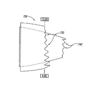
Figure 7 illustrates a nozzle 720 having first or fan flow projections 735
and second or core flow projections 745. The fan flow projections 735 and the
core
flow projections 745 vary in monotonic, opposite manners. That is, the fan
flow
projections 735 tend to be longer toward the bottom of the nozzle 720 than
toward the
top of the nozzle 720, while the core flow projections 745 vary in the
opposite manner.
-15-
CA 02839333 2014-01-13
The variation of the fan flow projections 735 is the opposite of the
arrangement of fan
flow projections 235 shown in Figure 3. Accordingly, this arrangement may be
suitable
when the nozzle 720 is carried by a pylon extending downwardly (rather than
upwardly)
from the engine. Such an arrangement is shown in Figure 8. In particular,
Figure 8
illustrates the wing 202 with an upper surface mounted pylon 807 carrying a
nacelle
804 housing the nozzle 720. In this arrangement, the trailing edge devices 208
deploy
downwardly (in a typical fashion) and, therefore, may not contribute
significantly to the
jet-flap interaction noise described above. However, the downstream wake of
the pylon
807 may interact with the exhaust products and accordingly, it may be
advantageous to
have the fan flow projections 735 be longer in a region adjacent to the pylon
807, than
in a region distant from the pylon 807.
Figure 9A illustrates an aircraft 900 having two engine nacelles 904a,
904b that depend from or are at least proximate to the fuselage 901. In this
particular
embodiment, each of the engine nacelles 904a, 904b is carried by the fuselage
901 via
a corresponding pylon 907. The nacelles 904a, 904b can include fan flow
projections
935a, 935b that are configured to reduce the noise transmitted to the interior
of the
fuselage 901 (e.g., the passenger compartment). In particular, the fan flow
projections
935a, 935b can be longer at a position close to the fuselage 901 than they are
in a
position distant from the fuselage 901. As a result, the fan flow projections
935a on the
left nacelle 904a tend to be longest near the 3:00 position, and shortest near
the 9:00
position, while the fan flow projections 935b on the second nacelle 904b have
the
opposite arrangement. It is expected that the enhanced mixing provided by the
longer
fan flow projections 935a, 935b near the fuselage 901 (which may have
relatively
greater immersion into the flow) can reduce the acoustic signature close to
the
fuselage 901, and can accordingly reduce the sound level experienced by
passengers
within the passenger compartment. The fan flow projections 935a, 935b that are
more
distant from the fuselage 901 can be shorter so as to reduce the overall
effect of the
fan flow projections 935a, 935b on engine thrust. Figure 9B illustrates an
acoustic
intensity vector A corresponding to the sound level expected to be produced by
the left
nacelle 904a at a given frequency. In particular, the net acoustic intensity
vector A
points outwardly away from the fuselage 901, indicating that sound levels are
expected
to be lower near the fuselage 901 than distant from the fuselage 901.
-16-
CA 02839333 2014-01-13
The manner in which the geometric features of the projections vary
around the perimeter of the nozzle can be selected to have a wide variety of
effects,
and different feature changes can be superimposed so as to address different
acoustic
requirements simultaneously. While superimposing different feature changes may
not
necessarily result in an optimum level of noise reduction for each
requirement, the
combination may be one that results in an overall noise reduction that meets
multiple
design requirements. For example, the longer fan flow projections 235
positioned
toward the top of the nozzle (described above with reference to Figure 3) may
be
combined with the longer projections 935a, 935b positioned toward the inboard
side of
the nozzle (described above with reference to Figure 9A). The result may be
fan flow
projections having an increased length toward the top of the nozzle to reduce
jet-flap
interaction noise, and also longer toward the fuselage to reduce cabin noise.
The
projections may be shorter toward the bottom of the nozzle and toward the side
of the
nozzle away from the fuselage, so as not to significantly impact the overall
exhaust
product mass flow and thrust level, in a region of the nozzle where reduced
acoustic
signature may not be as important as it is near the fuselage and near the
wing.
Figure 9C schematically illustrates a nacelle 904c and nozzle 920 having
projections configured to meet multiple acoustic objectives in the manner
described
above. In particular, longer projections 935c toward the top of the nozzle 920
are
positioned to reduce jet-mixing noise (e.g., due to an overhead wing and/or
pylon), as
represented by a first acoustic radiation vector A1. Longer projections 935d
toward the
inboard side of the nozzle 920 are positioned to reduce shock-cell noise, as
represented by a second acoustic vector A2.
Figure 9D schematically illustrates a nozzle 920 configured in accordance
with another embodiment of the invention to include two types of azimuthally
varying
projections: fan flow projections 935d that are longer and/or more immersed
toward the
top of the nozzle (near the pylon), and core flow projection 945d having
monotonically
decreasing lengths in a direction away from the fuselage 901. It is expected
that this
arrangement can reduce both community noise at low frequencies and
shockcell/cabin
noise at higher frequencies.
In still further embodiments, the manner in which the projections vary
around the nozzle perimeter (and therefore the degree of mixing between the
adjacent
-17-
CA 02839333 2014-01-13
flows) can be changed depending on flight regime of the aircraft, by changing
the
degree to which the projections are immersed as a function of time. This
arrangement
can be used to reduce different spectra of noise in different flight regimes.
For
example, to obtain more mixing between the fan flow and the freestreann air
near the
pylon (e.g., to reduce low-frequency noise during take-off), the projections
near the
pylon can be actively bent inwardly during takeoff. If mid-frequency shockcell
noise at
cruise is reduced by another type of azimuthal variation, (e.g., by immersing
projections
near the fuselage by a greater amount than projections away from the
fuselage), then
this change can be made during the appropriate flight regime (e.g., during
cruise).
Such desired azimuthal variations in projection immersions can be obtained,
for
example, by using shape memory alloys inside the projections and suitable heat
control
elements. This arrangement can be applied to fan flow projections, and/or core
flow
projections. Further aspects of active systems for accomplishing this
variation are
included in U.S. Patent No. 6,718,752.
As discussed above, certain aspects of the manners by which projection
geometric features are varied can be combined in a wide variety of ways.
Figure 10
illustrates schematically representative features that may be applied to the
fan flow
projections (along the horizontal axis), and/or the core flow projections
(along the
vertical axis). In these illustrations, R refers to regular or baseline
projections that do
not vary circumferentially, T refers to projections that are longer toward the
top than the
bottom, B refers to projections that are longer toward the bottom than the
top, K refers
to an arrangement in which projections are longer toward the top and the
bottom, and
V refers to an arrangement in which the immersion or degree to which the
projections
are bent inwardly toward the flow varies around the circumference of the
nozzle, but
the length does not. Depending upon the desired acoustic signature and the
particular
installation in which the nozzle is placed, these features may be combined in
any of a
variety of manners.
Figures 11A-11D illustrate representative features of individual
projections 1135 that may be varied in accordance with particular embodiments
of the
invention. For example, Figure 11A illustrates multiple projections 1135
located at a
perimeter 1121 of a corresponding nozzle 1120. Geometric features of each
projection
1135 that can be varied include the length 1122 of the projection 1135, the
width 1123
-18-
CA 02839333 2014-01-13
of the projection 1135, and/or the apex angle 1124 of the projection 1135. The
overall
shape of the projection 1135 may also be varied. For example, the projections
1135
can have a triangular or chevron shape as shown in Figure 11A, with generally
sharp
vertices, or the projections 1135 may have other shapes and/or shapes with
rounded or
other less abrupt transitions between edges. The number of projections 1135
per unit
length of the perimeter 1121 is another variable that may be selected to have
the
desired effect on the acoustic signature, again depending upon the particular
installation. As shown in Figure 11B, the angle 1125 between the projection
1135 and
the flow surface located just upstream of the projection 1135, or the
curvature of the
projection 1135 can also be varied so as to vary the immersion or degree to
which the
projection 1135 is deflected or bent inwardly into the nozzle flow. As shown
in Figure
11C, the density of projections 1135 (e.g., the number of projections 1135 per
unit
length along the nozzle exit perimeter) can also be varied. As noted above, in
particular embodiments, there may be portions of the nozzle perimeter or
circumference without projections, and/or the gap spacing between projections
may
vary in an irregular manner.
Many of the foregoing factors may be varied in combination with each
other to produce a desired geometry. For example, if each projection 1135 has
a fixed
width 1123, then reducing the length 1122 of the projection 1135 will change
the apex
angle 1124. In at least some embodiments, the projections 1135 form part of an
inwardly-sloping body of revolution around the axial centerline of the nozzle.
Accordingly, longer projections 1135 will tend to be more immersed in the
nozzle flow
than shorter projections. In other embodiments the projections can be
deflected
outwardly away from the nozzle centerline, as opposed to inwardly toward the
nozzle
centerline. Similar considerations can be applied to determine the geometric
features
of such projections.
In a particular embodiment shown in Figure 11D, at least some adjacent
projections can be alternately immersed inwardly and outwardly (e.g., by the
same
amount or by different amounts). Accordingly, the nozzle 1120 can include
pairs of
inwardly deflected projections 1135a and outwardly deflected projections
1135b. The
vortices from the adjacent edges of inwardly deflected projection 1135a and
neighboring outwardly deflection projection 1135b tend to merge to form only
one axial
-19-
CA 02839333 2014-01-13
vortex from those adjacent edges. Thus, for all practical purposes, each pair
of
alternately immersed projections can act like one projection having a larger
combined
width and a stronger axial vorticity. The parameters described above for
obtaining
azimuthal variation of mixing with respect to individual neighboring
projections can also
apply to each pair taken as a unit. For example, in order to obtain a
monotonic
variation in mixing from the top of the nozzle 1120 to the bottom of the
nozzle 1120 the
projections 1135a, 1135b can have a monotonically decreasing level of
immersion
(inwardly for the inwardly deflected projections 1135a and outwardly for the
outwardly
deflected projections 1136b) from top to bottom. In other embodiments, other
geometric characteristics of the projection pairs can be varied.
Figure 12 is a schematic illustration of four nozzles, labeled 1220a-d,
each of which has core flow projections with a different configuration, in
accordance
with several embodiments. For example, nozzle 1220a has core flow projections
that
do not vary in a circumferential direction, nozzle 1220b has core flow
projections that
are longer at the top than at the bottom, nozzle 1220c has the opposite
arrangement,
and nozzle 1220d has core flow projections that are longer at the top and
bottom and
shorter in an intermediate region. In this particular embodiment, the fan flow
projections for each of these nozzles are uniform. The graph of Figure 12
illustrates
the level of jet-flap interaction noise reduction associated with each of the
nozzle
configurations 1220a-d, as a function of frequency (on a logarithmic scale)
compared to
a simple round coaxial nozzle with no projections. Nozzles 1220a, b, d each
reduce
noise by a lesser amount a higher frequencies than at lower frequencies. By
contrast,
nozzle 1220c has a greater noise reduction capability at higher frequencies
than at
lower frequencies. Figure 12 accordingly indicates that the manner in which
the
geometric feature varies around the perimeter of the nozzle may be selected
based (at
least in part) on the frequency of the noise that is to be reduced. If lower
frequency
noise is to be reduced, nozzles 1220a, b or d may be appropriate, and if
higher
frequency noise is to be reduced, nozzle 1220c may be more appropriate.
Typically,
community noise is a greater problem at lower frequencies than at higher
frequencies,
while cabin noise is typically a greater problem at higher frequencies than at
lower
frequencies. Accordingly, the appropriate arrangement of nozzle projections
(or
combination of nozzle projection arrangements) can be selected in a manner
that
-20-
CA 02839333 2014-01-13
depends on the particular noise reduction target. Similar noise reduction
trends as a
function of frequency were found for nozzles having varying fan flow
projections and
uniform core flow projections; however, in at least some of these cases, the
reduction
in the noise that is due to jet-flap interaction was higher than for the
(baseline) nozzle
1220a.
Figures 13A-C and 14 illustrate still further geometric features that may
be varied to achieve desired thrust and acoustic signature results in
accordance with
further embodiments of the invention. In particular, Figures 13A-13C
illustrate nozzles
having different root locus lines 1326 (shown as root locus lines 1326a-1326c)
and tip
locus lines 1327 (shown as tip locus lines 1327a-1327c). The root locus lines
1326a-
1326b connect the root locations of successive fan flow projections 1335, and
the tip
locus lines 1327a-1327c connect the tip locations of the same projections
1335. Figure
13A illustrates a generally vertical root locus line 1326a and an aft-canted
tip locus line
1327a. Figure 13B illustrates a forwardly-canted root locus line 1326b and a
generally
vertical tip locus line 1327b. Figure 13C illustrates a forwardly-canted root
locus line
1326C, an aft-canted tip locus line 1327c, and a generally vertical centroid
locus line
1328c. The appropriate orientation of the root and tip locus lines may be
selected to
produce the desired acoustic vector, thrust vector, and/or other appropriate
parameter.
For example, canting the root locus line 1326 and/or the tip locus line 1327
may cant
the thrust vector. If a particular azimuthal arrangement of projections 1335
shifts the
thrust vector in an undesirable manner, canting the root locus line 1326
and/or the tip
locus line 1327 can be used to correct the thrust vector back to the desired
orientation.
This methodology is illustrated in the context of fan flow projections, but
may be applied
to core flow projections in addition to or in lieu of the fan flow
projections.
Figure 14 illustrates the "rolling ball" flow area through the fan flow duct
of
a nozzle configured in accordance with another embodiment of the invention.
Figure
14 illustrates that the nozzle has a locally convergent-divergent arrangement,
with a
geometric throat T upstream of a corresponding root locus line 1426. This
arrangement is expected to have several beneficial effects. For example, a
local
convergent-divergent region of the nozzle is expected to have enhanced
aerodynamic
effects at particular flight regimes. By positioning the geometric throat T
upstream of
the root locus line 1426, the effective exit area of the nozzle can be
controlled such that
-21-
CA 02839333 2014-01-13
it does not become susceptible to fan instability problems at low nozzle
pressure ratios
of the fan stream. The latter can occur when using inwardly immersed fan flow
projections which can aerodynamically effectively behave like convergent
nozzles. The
shape of the projections that controls the local convergent-divergent behavior
of the
rolling ball area can be used to control the effective exit area and avoid fan
instabilities.
It is expected that this arrangement can reduce thrust degradation. It will be
understood that in at least some cases, the nozzle can include an aerodynamic
convergent section downstream of the local convergent-divergent region
discussed
above.
From the foregoing, it will be appreciated that specific embodiments of
the invention have been described herein for purposes of illustration, but
that various
modifications may be made without deviating from the invention. For example,
several
of the embodiments described above were described in the context of nozzles
having
core flow paths that extend axially further aft than the corresponding fan
flow paths
(e.g., externally mixed nozzles). In other embodiments, the nozzles may be
internally
mixed and may have fan flow paths that extend further aft than the
corresponding core
flow paths. The nozzles may have a variety of exit perimeter shapes, including
round,
rectangular and elliptical.
Still further embodiments are described in the following documents: AIAA
Paper 2006-2467, entitled "Reducing Propulsion Airframe Aeroacoustic
Interactions
with Uniquely Tailored Chevrons: 1. Isolated Nozzles," dated May 8-10, 2006;
AIAA
Paper 2006-2434, entitled "Reducing Propulsion Airframe Aeroacoustic
Interactions
with Uniquely Tailored Chevrons: 2. Installed Nozzles," dated May 8-10, 2006;
AIAA
Paper 2006-2435, entitled "Reducing Propulsion Airframe Aeroacoustic
Interactions
with Uniquely Tailored Chevrons: 3. Jet-Flap Interaction," dated May 8-10,
2006; AIAA
Paper 2006-2439, entitled "Flight Test Results for Uniquely Tailored
Propulsion-
Airframe Aeroacoustic Chevrons: Shockcell Noise," dated May 8-10, 2006; AIAA
Paper 2006-2438, entitled "Flight Test Results for Uniquely Tailored
Propulsion-
Airframe Aeroacoustic Chevrons: Community Noise," dated May 8-10, 2006; AIAA
Paper 2006-2436, entitled "Computational Analysis of a Chevron Nozzle Uniquely
Tailored for Propulsion Airframe Aeroacoustics," dated May 8-10, 2006; AIAA
Paper
2005-0996, entitled "Relative Clocking of Enhanced Mixing Devices for Jet
Noise
-22-
CA 02839333 2014-01-13
Benefit," dated January 10-13, 2005; AIAA Paper 2005-2934, entitled "Jet Noise
Characteristics of Chevrons in Internally Mixed Nozzles," dated May 23-25,
2005; and
AIAA Paper 2006-0623, entitled "Internal Flow and Noise of Chevrons and Lobe
Mixers
in Mixed-Flow Nozzles," dated January 9-12, 2006.
Aspects of the invention described in the context of particular
embodiments may be combined or eliminated in other embodiments. For example,
many of the geometric features described individually above may be combined in
any
of a variety of manners to meet corresponding acoustic and thrust design
goals, while
integrating appropriately with other structures of the aircraft into which the
nozzles are
integrated. Further, while advantages associated with certain embodiments of
the
invention have been described in the context of those embodiments, other
embodiments may also exhibit such advantages, and not all embodiments need
necessarily exhibit such advantages to fall within the scope of the invention.
Accordingly, the invention is not limited, except as by the appended claims.
-23-