Note: Descriptions are shown in the official language in which they were submitted.
CA 02839358 2013-12-13
WO 2013/006970
PCT/CA2012/050469
COMPACT LIGHT HOMOGENIZER
TECHNICAL FIELD
[0001] Various embodiments are described herein relating generally to the
field of
illumination, and more particularly to produce substantially uniform
illumination from at
least one light source.
BACKGROUND
[0002] Light sources, such as light emitting diodes (LEDs), incandescent
lamps and the
like, generally require light mixing, or homogenization to produce a
substantially uniform
illumination. Such uniform illumination is beneficial in various applications,
such as image
projectors (e.g., motion picture) or microscope illuminators. Methods for
accomplishing
uniform illumination have included imaging relatively uniform sources, or
using illumination
optics such as Koehler systems. To accomplish similar results with highly non-
uniform
sources, such as LEDs, or worse, arrays of LEDs, high performance homogenizers
are
needed.
[0003] Light sources, such as LEDs, or multiple LEDs, possibly of different
color (e.g.,
separate red, green and blue LEDs as may be used in a color imaging system),
require
additional optics to create a uniform light source needed for projectors and
microscopy. For
example, individual LED dies can be spatially separated. Since the eye is
particularly
sensitive to color, special provisions are necessary to ensure that the
independent colors are
mixed at a common target.
[0004] Solutions for light mixing, or homogenization that create uniform
light sources
include lenslet array and light pipe designs. One example of such a system is
provided in
U.S. Published Patent Application No. 2006/0262282, to Magarilll, addressing
the problem of
producing uniform light from a LED or multiple LEDs, potentially of different
wavelengths
using light pipes.
[0005] Lenslet array homogenizers are preferred in many applications as
they are quite
compact and their production is usually accomplished by a molding process,
which makes
economic sense in large volume production. Unfortunately, lenslet homogenizers
typically
need to be designed for a specific system, with large initial costs for
moulds, and potentially
limited homogenization performance compared to other solutions.
1
CA 02839358 2013-12-13
WO 2013/006970
PCT/CA2012/050469
[0006] Light pipe homogenizer designs tend to be more flexible, allowing a
standard
product to be used in different Illumination systems. Also, custom hollow
light pipes are
usually quite inexpensive to obtain even in small quantities. This lends light
pipes to be a
preferred choice for small to medium volume production due to their low cost,
high
homogenization and good power efficiency. Additionally, some light pipe
homogenizers can
out perform lenslet arrays in the task of homogenization. A disadvantage of
light pipe
homogenizers, however, especially with high-performance homogenization
characteristics, is
that they are not as compact as lenslet homogenizers. For a light pipe
homogenization
system, the light pipe alone can be ten times (10x) longer than it is wide.
This length does
not include the length of other aspects of any realizable system, such as the
collecting and
condensing optics. Thus, either approach presents challenges as more compact
systems are
preferred for all the typical reasons, such as cost, weight, portability, etc.
SUMMARY
[0007] Described herein are embodiments of systems and techniques for
achieving
desirable homogenization and mixing of one or more light sources that can be
economically
realized within a compact profile. More particularly, the devices and
techniques described
herein involve the use of diffusers and light pipes in a particular
configuration that allows
very good homogenization performance while reducing the requisite length of
light pipe. For
example, by placing a diffuser at a point along a light pipe where the light
from each source
or each portion of a single source substantially covers the diffuser
approximately equally, the
rate of homogenization can be increased, thereby reducing the required length
of the
complete homogenization system. This diffuser position can be after an initial
section of
light pipe, or potentially in or near collimated space after the source(s).
[0008] In one aspect, at least one embodiment described herein provides a
compact light
homogenizer, including a light pipe extending along an optical axis between
two ends. The
homogenizer also includes a diffuser positioned along the optical axis and
between the two
ends.
[0009] In some embodiments, the diffuser of the compact light homogenizer
is positioned
to substantially bisect the light pipe. The diffuser can include a randomized
surface structure
or an engineered structure to provide tailored diffusion.
[0010] In another aspect, at least one embodiment described herein relates
to a process
for homogenizing illumination from a light source. The process includes
coupling into a light
2
CA 02839358 2013-12-13
WO 2013/006970
PCT/CA2012/050469
pipe, illumination from the light source. The coupled light is mixed along a
first length of the
light pipe and then diffused. The diffused light is further mixed along a
second length of the
light pipe. In at least some embodiments, mixing can include total internal
reflection.
[0011] In yet another aspect, at least one embodiment described herein
provides an
illumination system, including at least one light source and a light pipe
configured to couple
illumination from the at least one light source. The light pipe extends along
an optical axis
between a source end and a target end. The system also includes a diffuser
positioned along
the optical axis and between the source and target ends. In at least some
embodiments, the
diffuser can be positioned to substantially bisect the light pipe.
BRIEF DESCRIPTION OF THE DRAWINGS
[0012] The foregoing and other objects, features and advantages of the
invention will be
apparent from the following more particular description of preferred
embodiments of the
invention, as illustrated in the accompanying drawings in which like reference
characters
refer to the same parts throughout the different views. The drawings are not
necessarily to
scale, emphasis instead being placed upon illustrating the principles of the
invention.
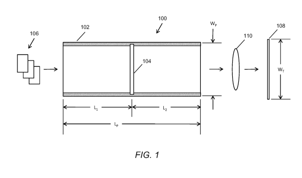
[0013] FIG. 1 illustrates a cross-sectional diagram of an embodiment of a
compact light
source homogenizer.
[0014] FIG. 2 illustrates a cross-sectional diagram of another embodiment
of a compact
light source homogenizer.
[0015] FIG. 3A illustrates a series of illuminations for light pipes of
various lengths.
[0016] FIG. 3B illustrates a series of illuminations for light pipes of
various lengths, each
bisected by a respective diffuser.
[0017] FIG. 4 illustrates a schematic diagram of an optical system
including an
embodiment of a compact light source homogenizer.
[0018] FIG. 5 illustrates a schematic diagram of an optical system
including an
embodiment of a compact light source homogenizer.
[0019] FIG. 6 illustrates a process for homogenizing illumination from a
light source.
DETAILED DESCRIPTION
[0020] A description of embodiments of systems and processes for achieving
desirable
homogenization and mixing of one or more light sources that can be
economically realized
within a compact profile follows. More particularly, the devices and
techniques described
3
CA 02839358 2013-12-13
WO 2013/006970
PCT/CA2012/050469
herein involve the use of diffusers and light pipes in a particular
configuration that allows
very good homogenization performance while reducing the requisite length of
light pipe.
[0021] The length of a light-pipe homogenizer can be substantially reduced
by diffusing
the light after it has been partially pre-mixed by a light pipe with a
diffuser. For example, by
placing a diffuser at a point along a light pipe where the light from each
source or each
portion of a single source substantially covers the diffuser approximately
equally, the rate of
homogenization can be increased, thereby reducing the required length of the
complete
homogenization system. This diffuser position can be after an initial section
of light pipe, or
potentially in or near collimated space after the source(s). In at least some
embodiments, the
diffuser can be a low-angle engineered diffuser, followed by additional mixing
within a light
pipe. In particularly compact solutions of this system a diffuser is
sandwiched between two
light pipes, or otherwise inserted within a light pipe.
[0022] The diffuser boosts the mixing rate, reducing the required light
pipe length to
achieve a given homogenization level. The diffuser has the largest impact when
light from
each source illuminates the entire diffuser surface, which occurs in or near
collimated space,
or after some homogenization has already occurred, such as after a section of
light pipe.
Diffusing increases the &endue of the system, which typically causes some
power loss.
(Etendue is generally understood to related to a property of pencils of rays
in an optical
system, which characterizes how "spread out" light is in area and angle. From
the system
point of view, the &endue is the area of the entrance pupil times the solid
angle the source
subtends as seen from the pupil.) It may also be seen as a volume in phase
space). Light
within the numeric aperture accepted by the following optics is scattered to a
higher angle of
incidence outside of the accepted numeric aperture. However, by filling the
first light pipe
with a higher numerical aperture (NA) light than can normally be used by the
following
system the diffusion process replaces some of the "lost" light, with high NA
light scattered
down to an accepted NA by the diffuser. Since this entire process happens
within a light
pipe, the lateral width of the optical system is constrained to a much small
dimension than
would occur within a typical lensed optical system.
[0023] When the modified light pipes described herein are used with a
source that has a
higher &endue than following optical system, the power loss that normally
occurs using a
diffuser can be mitigated by recycling normally unused high NA light when it
is scattered
down to an accepted NA by the diffuser. The homogenization system can work
with
4
CA 02839358 2013-12-13
WO 2013/006970
PCT/CA2012/050469
monochromatic or polychromatic source, single or multiple sources, of
differing or similar
wavelengths.
[0024] Illustrated in FIG. 1 is a cross section of a modified light pipe
100. The light pipe
extends along a longitudinal axis between a light source 106 (shown in this
illustrative
embodiment as including three distinct light sources, e.g., red, green and
blue LEDs) and a
target 108 (e.g., a target portion of a user display). The modified light pipe
100 includes a
standard light pipe as is generally understood by those skilled in the art,
modified to include
at least one diffuser 104. As illustrated, the light pipe 102 is a hollow
light pipe, with a
planar diffuser 104 located at a length L1 from a source end and a length L2
from a target end.
The overall length of the modified light pipe 100 is L = L1+ L2.
[0025] As illustrated, the diffuser can be retained within a groove or
recess within a wall
of the light pipe 100. Alternatively or in addition, the diffuser 104 can be
retained in position
with an adhesive, thermal bonding, welding or with mechanical fasteners or
clamps.
Although the light pipe 100 is shown as a continuous member, it is also
possible that the light
pipe include two or more sections, for example, a respective section along
either side of the
diffuser 104.
[0026] Light pipes generally achieve homogenization by total internal
reflection for solid
pipes and dielectric and/or metallic reflective coatings for hollow pipes.
Such light pipe
structures can include one or more of hollow structures (pipes) and solid
structures (rods).
Such structures can be combined with one or more of reflective coatings and
dielectric
coatings, for example, of differing indexes of refraction. Some examples of
light pipes
include N-BK7 Light Pipe Homogenizing Rods and TECHSPECO Tapered Light Pipe
Homogenizing Rods, each available from Edmund Optics, Inc. of Barrington NJ.
[0027] Diffusers can include precisely shaped holograpically recorded
randomized
surface structures. Such structures can enable one or more of high
transmission efficiency,
beam shaping and homogenized light output. Some examples of such diffusers are
LSD
diffusers commercially available from Luminit Co., of Torrance, CA. Other
diffusers include
patterned structures, such as lenslet arrays and other random structures, such
as ground glass.
Another class of diffusers would be volume scattering materials such as "opal
glass".
[0028] An alternative embodiment of a modified light pipe 200 is
illustrated in FIG. 2. In
this embodiment, a thin diffuser 204 is located between two solid light pipe
segments 202a,
202b. In some embodiments, the diffuser 204 can be bonded between the light
pipe segments
202a, 202b. Alternatively or in addition, the diffuser 204 and light pipe
segments 202a, 202b
CA 02839358 2013-12-13
WO 2013/006970
PCT/CA2012/050469
can be retained within another housing, frame, or clamping structure (not
shown) to retain
their arrangement.
[0029] FIG. 3A and 3B show a simple example in which the homogenization
capability
of a light pipe of various lengths is compared with (FIG. 3B) or without (FIG.
3A) a diffuser
bisecting the length of the light pipe. Referring first to FIG. 3A, a light
pipe is illustrated as
the elongated gray rectangle of length L. Dashed lines along the light pipe
are intended to
illustrate a similar light pipe of differing lengths ranging from very short
(left hand side of the
image) to full length (right hand side of the image). Also illustrated above
the light pipe are a
series of images (a) through (e). Image (a) associated with the shortest light
pipe represents a
white square on a black field. The white square represents the image (a
similar white square)
viewed through an extremely short segment of light pipe. Image (b) represents
the same
source seen through a greater length of light pipe, and so forth, each image
representing a
respective level of homogenization of the source, until a completely white
image is shown in
image (0. Image (0 represents a fully homogenized source obtained at light
pipe of length L.
[0030] Likewise, referring next to FIG. 3B, a light pipe is illustrated as
the elongated
shaded rectangle of length L. Dashed lines along the light pipe are intended
to illustrate a
similar light pipe of differing lengths ranging from very short (left hand
side of the image) to
full length (right hand side of the image). The difference being that for each
length of light
pipe, the respective light pipe is bisected by a diffuser, such as the
diffusers described herein.
[0031] Also illustrated below the light pipe are a similar series of images
(a) through (0.
Associated with the modified light pipe, image (e) represents a fully
homogenized source
obtained at light pipe of a length substantially less than L. Quite
significantly, image (e) was
obtained for a light pipe of length L/2, bisected by a diffuser. Thus, full
homogenization can
be obtained with a modified light pipe that is half the length of an
unmodified light pipe.
Said differently, a light pipe without a diffuser must be two times longer to
achieve the same
approximate homogenization performance of a light pipe with a bisecting
diffuser half its
length.
[0032] Although the illustrative example describes modified light pipes
having diffusers
located substantially at their respective mid sections, it is contemplated
that improved
performance (i.e., equivalent homogenization at shorter lengths) can be
obtained for modified
light pipes having a diffuser positioned at different locations along the
light pipe's length.
[0033] FIG. 4 shows the four types of rays in a system that has a light-
pipe accepting
light of a larger &endue than what is accepted by the following optical
system. In this
6
CA 02839358 2013-12-13
WO 2013/006970
PCT/CA2012/050469
situation, where the &endue of the following optical system is smaller than
the preceding
section, some light has to be lost in the process, so that the accepted
incoming light has an
&endue equal to that of the receiving optics. In this situation, when the
homogenization is
increased by the use of a diffuser, which raises the &endue, additional light
is lost. In this
invention, this loss is partially alleviated by recycling light that would
normally never be used
by a system without a diffuser. In a light pipe homogenizer with equal input
and output
apertures, the numeric aperture of the light is proportional to the &endue of
that light. Light
with a high numeric aperture, or high angle of incidence would not normally be
accepted by
the following optical system. However, some high numeric aperture light
scatters off the
diffuser into a lower angle of incidence, which can then be accepted by the
next optical
section. This recycling of light allows a system with a light source with a
higher &endue than
what is accepted by the following optical system to benefit from the reduced
homogenizer
sized provided by this invention, with limited power loss normally seen by
using a diffuser.
[0034] FIG. 5 shows a system with a source with a NA of 0.26 and a
following optical
system that can accept an NA of 0.2. In this case, the system without a
diffuser would couple
55% of the source light. The same system with a diffuser would couple 50% of
light. This
relatively small power loss is due to the recycling 9% of the higher NA light
into a lower
usable NA. Without this effect, the diffuser system would have coupled only 41
% of the
light from the source. In certain situations, such as with very large NA
sources, the diffuser
system can couple more light than without a diffuser.
[0035] FIG. 6 illustrates an embodiment of a process for homogenizing
illumination from
a light source. The process includes a first step in which illumination from a
light source is
coupled into a light pipe. The coupled illumination is partially mixed along a
first length of a
light pipe. The partially mixed light is then diffused and further mixed along
a second length
of the light pipe. Light exiting the light pipe is substantially mixed and
otherwise
homogenized.
[0036] Mixing devices or Illuminators are an existing need globally. In
addition to
display applications, other companies requiring uniformly mixed light from
different sources
also include the Abbott blood analysis microscope and other medical
microscopes for blood
analysis. Many additional markets, including projectors, and any other display
device
requiring the production of uniform light in a short distance can benefit from
this technology.
7
CA 02839358 2013-12-13
WO 2013/006970
PCT/CA2012/050469
[0037] Comprise, include, and/or plural forms of each are open ended and
include the
listed parts and can include additional parts that are not listed. And/or is
open ended and
includes one or more of the listed parts and combinations of the listed parts.
[0038] One skilled in the art will realize the invention may be embodied in
other specific
forms without departing from the spirit or essential characteristics thereof
The foregoing
embodiments are therefore to be considered in all respects illustrative rather
than limiting of
the invention described herein. Scope of the invention is thus indicated by
the appended
claims, rather than by the foregoing description, and all changes that come
within the
meaning and range of equivalency of the claims are therefore intended to be
embraced
therein.
8