Note: Descriptions are shown in the official language in which they were submitted.
CA 02839482 2014-01-16
TILE ALIGNMENT AND LEVELING DEVICE
This invention is directed to the field of laying and leveling tile and slabs.
More
particularly, the invention is directed to a device for aligning and leveling
adjacent tiles
as they axe laid in floors, walls, countertops, or the like.
Tile has become a popular decorative and functional article for use in floors,
walls, countertops, and the like. Both professional tile installers and do-it-
yourselfers
spend a great deal of time aligning and leveling tiles as the tiles are being
placed on a
substrate's surface. Proper alignment and leveling of each tile is important
for a
number of reasons. One reason is that if one tile is improperly placed, the
error will
continue in adjacent tiles such that the installation will be unacceptable and
the tiles will
have to be replaced and/ or ground and polished until the tiles are level or
flat. In
addition to aesthetic reasons for properly laying tile, a level surface is
essential in tile
floors so that people do not trip and fall on unevenly laid tiles. Replacing
or otherwise
correcting errors in tile installation takes time that adds to the total cost
of the tile
installation.
Laying and leveling tile can be difficult because many substrates are uneven,
such as the ground substrate when laying tile for an outdoor patio. In this
case, it can
be difficult to raise the low areas of the substrate with mortar or other
objects so that all
the tiles are level. Further, tiles can shift and sink into mortar as the
mortar dries. It has
traditionally been necessary to continually monitor newly laid tiles as the
mortar dries
to ensure that the tiles remain level. Tile installers have used a variety of
devices and
methods to maintain quality tile installation while completing the
installation process as
1
CA 02839482 2014-01-16
fast as possible. One basic method uses markings on the substrate surface.
Marking the
installation surface requires the mortar to be carefully applied such that the
marks
remain visible. Although this technique aids in the alignment of the tiles, it
does not
keep the tiles level as they are laid in the mortar. Further, the use of this
marking
technique increases the amount of time required for the installation which
results in
increased cost.
Another device used for laying and leveling tile is a frame designed to space
tiles
art appropriate distance. This type of frame is typically a fixed grid which
is designed
for a specific tile size. The disadvantage of this type of device is that it
is a fixed size
which requires a professional installer to carry multiple frames in order to
be capable of
installing various tile sizes. A further disadvantage of this type of frame is
that it is only
capable of installing one type of tile at a time.
Another device used to lay and align adjacent tiles is a spacer such as the
one
described in U.S. Patent Number 6,625,951 (McCarthy). The spacer disclosed in
this
patent provides a square edge for properly aligning adjacent tiles at right
angles, and a
height adjustment means for adjusting the height of the tiles relative to the
mortar
surface. One problem with this device is that it is difficult to set multiple
spacers to the
same height which often results in an uneven tile surface. A related problem
with this
device is that the adjustment means does not allow the height of the tiles to
be adjusted
after the tile is laid because the height adjustment means is located under
the tile after
the tile is laid.
2
CA 02839482 2014-01-16
Therefore, there is a need for an efficient and inexpensive tile leveling and
alignment device that allows for the vertical adjustment of tiles relative to
each other
after the tiles have been laid in the mortar.
SUMMARY OF THE INVENTION
The present invention is directed to a tile leveling and alignment device for
use
in installing tiles on substrates such as floors, walls, countertops, or the
like. The
invention comprises a locking assembly and a bottom plate. These components
are
combined with a shaft that extends from the bottom plate through the locking
assembly
so that the locking assembly is movable along the length of the shaft. A
typical first step
in laying tile is the application of a setting bed, such as a cement or mortar
compound,
to the substrate surface. Thereafter, the tiles can be placed in the setting
bed. During
these steps the bottom plate is positioned in the setting bed beneath the
tiles so that the
shaft extends upward between adjacent tiles. The bottom plate is preferably
positioned
so that it is in contact with more than one tile. The shaft extends from the
bottom plate
upward between adjacent tiles and is combined with the locking assembly. The
locking
assembly is movably combined with the shaft so that after the tiles are laid
in the setting
bed on top of the bottom plate, the locking assembly is moved toward the tiles
until the
tiles are between and in contact with the locking assembly and bottom plate.
The plates
support the tiles so that adjacent tiles remain level even if the substrate
material is not
level. In other words, the device keeps the tiles level relative to the
adjacent tiles, not
relative to the substrate surface. The device holds the tiles at the same
height so that
3
CA 02839482 2014-01-16
corners and/or edges of the adjacent tiles remain level in the setting bed as
the setting
bed dries and cures.
After the setting bed dries, thereby securing the tiles to the substrate, the
shaft is
separated from the bottom plate leaving the bottom plate beneath the set
tiles. The
locking assembly and the portion of the shaft above the separation point are
released
from the set tiles allowing the locking assembly to be reused in subsequent
tile setting
and leveling procedures.
One of ordinary skill in the art would understand that a plurality of tile
leveling
devices can be simultaneously used between different tiles being laid on a
substrate so
as to level many tiles at the same time.
BRIEF DESCRIPTION OF THE DRAWING
FIG. 1 is a side view of an embodiment of the device of the present invention;
FIG. 2 is a side view of an embodiment of the device of the present invention
in
use between two adjacent tiles;
FIG. 3 is a perspective view of the embodiment shown in FIG. 1;
FIG. 4 is a perspective view of an embodiment using a resilient pad to assist
with
tile alignment;
FIG. 5 is a side view of the embodiment shown in FIG. 4 in use between two
adjacent tiles;
FIG. 6 is a perspective view showing an embodiment having a top plate that is
separate from the locking assembly;
4
CA 02839482 2014-01-16
FIG. 7 is a perspective view of an embodiment having a top plate that is
combined with the locking assembly; and
FIG. 8 is a perspective view of an embodiment similar to the embodiment shown
in FIG. 1.
DESCRIPTION OF THE PREFERRED EMBODIMENT OF THE INVENTION
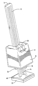
The present invention is a tile 18 alignment and leveling device. The device
can
be used to align and level tiles 18 that are being secured to any suitable
substrate,
including floors, walls, and countertops. It should be noted that words used
in this
specification such as upper, lower, top, and bottom, are relative to the
device as it is
shown in FIG. 2 with the locking assembly 33 above the bottom plate 12.
As best seen in FIG. 1, the present invention comprises a locking assembly 33
and
a bottom plate 12 combined with a shaft 14. The plate 12 can be made from any
suitable
material, however, it is preferably comprised of plastic or nylon with a metal
reinforcing insert embedded inside. The metal insert provides strength and
rigidity to
the plate 12 that may be needed for leveling heavy tiles 18 or slabs, while
the outer
plastic (or nylon) portion prevents damage to the tiles 1.8 and does not rust.
The shaft
14 is preferably comprised primarily of flexible nylon, thereby making the
shaft 14
semi-rigid.
A typical first step in laying tile 18 is to apply a setting bed 20 such as
mortar or
cement to the substrate surface 22. After the setting bed 20 is applied, the
tiles 18 can be
placed in the setting bed 20. In use, the bottom plate 12 of the device is
positioned in
CA 02839482 2014-01-16
the setting bed 20 beneath the tiles 18 so that the shaft 14 extends upward
between
adjacent tiles 18, preferably at joint or corner locations. The shaft 14
extends from the
bottom plate 12 upward between the tiles 18 and is combined with the locking
assembly
33, which is positioned above the tiles 18. The locking assembly 33 is moved
along the
shaft 14 toward the tiles 18 until the tiles 18 are in contact with the
locking assembly 33
and bottom plate 12 as shown in FIG. 2. The plate 12 and locking assembly 33
hold the
tiles 18 at their desired height so that adjacent tiles 18 are level
regardless of whether the
underlying substrate material 22 is level. In other words, the bottom plate 12
does not
need to rest on the substrate in order for the tiles 18 to be level. The
bottom plate 12
may even be suspended above the substrate as long as at least a portion of the
tile 18 is
contacting the setting bed 20 and as long as the tiles 18 are level relative
to each other.
The plate 12 and locking assembly 33 hold the tiles 18 at the same height so
that corners
and/or edges of the adjacent tiles 18 remain aligned and level as the setting
bed 20
hardens.
Once the tiles 18 are properly positioned, the locking assembly 33 is secured
in
its place adjacent to the tiles 18 and prevented from moving upward along the
shaft 14.
Various embodiments of the locking assembly 33 are seen in FIGS. 1, 6, and 7.
In some
embodiments, the locking assembly 33 comprises at least one locking tongue 30
which,
together with the shaft 14, functions like a commercially available "zip tie."
In other
words, the locking tongue 30 allows the locking assembly 33 to move freely in
a first
direction (downward) along the length of the shaft 14, but not in a second
direction
(upward) along the length of the shaft 14. The locking tongue(s) 30 of the
locking
6
CA 02839482 2014-01-16
assembly 33 are angled and adapted to interfere with the shaft 14 to allow
movement in
only one direction (downward).
As shown in FIG. 6, the locking tongues 30 may comprise a tongue release 31.
Activation of the tongue release 31 enables the user to release the locking
tongues 30
from the surface features 1.5 on the shaft 14 to allow movement of the locking
assembly
in the second (upward) direction.
FIG. 6 shows an alternate embodiment further comprising a top plate 10 which
is
separate from the locking assembly 33. In this embodiment, different top
plates 10
having different sized fins 26 can be used with the same locking assembly 33.
In this
embodiment, locking assembly 33 preferably comprises members 35 which are
received
by openings (not shown) on the underside of locking assembly 33 to hold the
locking
assembly 33 together with the locking assembly 33 by an interference fit
during use.
As seen best in FIGS. 3 and 7, the bottom plate 1.2 preferably comprises one
or
more openings 28. The openings 28 allow the setting bed material 20 to seep
through
the bottom plate 1.2. This seepage allows the setting bed material 20 to bond
with the
portion of the tile 18 directly above the bottom plate 12, which otherwise may
not
contact much of the setting bed material 20. Further, the seepage helps to
ensure that
the tiles 18 remain level as forces are applied to the plate 12, sett-ing bed
material 20,
and/or tiles 18 during tightening, leveling, and setting. If the setting bed
material 20
was not allowed to seep through the bottom plate 12, the setting bed material
20 could
raise the bottom plate 12 as it dried which would consequently affect the
level of the
tiles 18.
7
CA 02839482 2014-01-16
After the setting bed 20 dries, and the tiles 18 are secured to the substrate
22, the
user removes the portion of the device that is visible above the laid tiles
18, i.e. the shaft
14 and locking assembly 33. In one embodiment, the shaft 14 comprises a
separation
point 16 near the connection of the shaft 14 and the bottom plate 12 as seen
in FIGS. 6
and 8. The separation point 16 is structurally weaker than the remainder of
the shaft 14
so that the user can apply force to the portion of the shaft 14 that extends
above the tiles
18 and cause the shaft 14 to break at its separation point 16. In the
embodiment shown
in FIG. 6, the separation point 16 comprises a single opening which allows the
separation point 16 to be structurally weaker and separate when the proper
force is
applied by the user. In the embodiment shown in FIG. 8, the separation point
16
comprises a plurality of micro holes or perforations which allow the
separation point 16
to be structurally weaker and separate when the proper force is applied by the
user. In
one embodiment, the curing process of the setting bed 20 pulls moisture out of
the shaft
14 making it more brittle, This makes it easier for the user to break the
shaft 14 at the
separation point 16. Once separated at the separation point 16, the bottom
plate 12
remains below the tiles 18 and is therefore not reusable. The locking assembly
33,
however, can be removed from the shaft 14 and reused in subsequent tile 18
laying
operations. As discussed above, the shaft 14 is preferably made of a semi-
rigid nylon.
This semi-rigid material allow the shaft 14 to more easily be broken at its
separation
point 16.
FIGS. 1-3 and 8 show an embodiment wherein at least a portion of the bottom
plate 12 is comprised of a material that has a flexible or spring-like
quality, such as a
8
CA 02839482 2014-01-16
plastic composite. The flexible portion 50 of the bottom plate 12 can move
between a
compressed position and an extended position. The flexible portion 50 of the
bottom
plate 12 is biased in its extended position. As shown in FIG. 8, the flexible
portion 50 of
the bottom plate 12 may be tapered so that it is thinner at its outer end to
allow the
device to be easily inserted under tiles 18.
As seen in FIG. 2, this embodiment is useful in situations where adjacent
tiles 18,
18a have different thicknesses. The flexible portion 50 of the bottom plate 12
can be
compressed under the weight of the thicker (heavier) tile 18a, while the
flexible or
spring-like quality of the bottom plate 12 can remain in its extended position
under the
thinner (lighter) tile 18 thereby holding the two adjacent tiles 18, 18a at
the same
elevation. In the mariner, the tile alignment arid leveling device is self-
adjusting after it
has been placed under the tiles 18, 18a. When the device is used at the
intersection of
four tiles 18, each of the four flexible portions 50 can be positioned under
each of the
four tiles 18 to independently hold each tile 18 at the same elevation.
Although this
embodiment is shown in FIGS. 3 and 8 as having four flexible portions
("wings"), the
flexible portion 50 can be any other suitable shape with any suitable number
of wings.
In the embodiment shown in FIG. 8, each flexible portion 50 begins near the
center of the bottom plate 12 and extends upward and outward therefrom. In the
embodiment shown in FIGS. 1 - 3, each flexible portion 50 begins near the
outer corner
of the bottom plate 12 and extends upward and inward.
FIGS. 4 and 5 show an embodiment which comprises a resilient pad 60 adapted
to be inserted between the tile 18 and the bottom plate 12. In one embodiment,
the
9
CA 02839482 2014-01-16
resilient pad 60 is a separate component from the bottom plate 12. In an
alternate
embodiment, the resilient pad 60 is secured to the bottom plate 12 during
manufacture
of the bottom plate 12. The resilient pad 60 has a flexible or spring-like
quality and is
made of a material such as a high-density resilient foam. The resiliency of
the resilient
pad 60 allows it to move between a compressed position and an extended
position. The
resilient pad 60 is biased in its extended position. As seen in FIG. 5, this
embodiment is
useful in situations where adjacent tiles 18, 18a have different thicknesses.
After being
positioned on the bottom plate 12 and placed under the tiles 18, 18a, the
resilient pad 60
is compressed under the weight of the thicker (heavier) tile 18a, while it
remains
extended under the thinner (lighter) tile 18, thereby holding the two adjacent
tiles 18,
18a at the same elevation.
As shown in FIG. 1, in some embodiments, some or all of the shaft 14 is made
of
a soft plastic or an elastic material that allows the shaft 14 to stretch
longitudinally
when force is applied. In use, the locking assembly 33 can be positioned
against the tile
18 so that the shaft 14 is stretched thereby causing the locking assembly 33
and the tile
18 to be forced together by the resiliency of the shaft 14. At the same time,
an upward
force would be exerted on the tile 18 by the resilient pad 60 (if that
embodiment were
being used) or flexible portion 50 (if that embodiment were being used)
thereby helping
to secure and hold the tile 18 in the proper position.
The scope of the claims should not be limited by the preferred embodiments set
forth in the examples, but should be given the broadest interpretation
consistent with
the description as a whole.