Note: Descriptions are shown in the official language in which they were submitted.
CA 02839487 2013-12-16
CA Apphcation
Blakes Ref: 10798/00003
1 AUDIO SIGNAL RECEIVING DEVICE, AUDIO SIGNAL ADAPTER DEVICE AND SYSTEM
2 FOR TRANSMITTING AUDIO SIGNAL
3 FIELD
4 The present invention generally relates to an electronic technical field,
and more particularly
relates to an audio signal receiving device, and an audio signal adapter
device and a system for
6 transmitting an audio signal.
7 BACKGROUND
8 With the development of an audio signal coding/decoding technology, more
and more
9 electronic equipments transmitting data via an audio interface are
produced. For example, the
electronic equipment may be connected with a mobile communication device via a
11 low-resistance voice coil type of loudspeaker interface (such as a
headphone interface) of the
12 mobile communication device (such as a mobile phone) for receiving an
audio signal output
13 from the mobile communication device.
14 As an output power of the low-resistance voice coil type of loudspeaker
interface is usually
very low, except the electronic equipment (such as a headphone) with low power
consumption,
16 the electronic equipment receiving the audio signal via the low-
resistance voice coil type of
17 loudspeaker interface generally needs to use an external power source or
an internal battery for
18 normal working, which increases a cost of the electronic equipment and
enlarges a volume of
19 the electronic equipment.
For solving the above problems, the inventors propose an audio signal adapter
device
21 (such as an audio cable) having a power supplying function, such that
the audio signal adapter
22 device can supply power to an audio signal receiving device at the same
time when sending an
23 audio signal to the audio signal receiving device.
24 Fig. 1 is a schematic diagram of an audio cable having a power supplying
function. As
shown in Fig. 1, the audio cable comprises: a loudspeaker interface (a
headphone plug as
26 shown in Fig. 1), a boosting unit (a boosting transformer as shown in
Fig. 1), a rectifying unit (a
27 rectifier as shown in Fig. 1), a filtering unit, and a USB plug,
28 The headphone plug is configured to be connected with a headphone jack
of the audio
29 signal sending device (such as the mobile phone), and to receive the
audio signal output from
the audio signal sending device.
2248433/1
CA 02839487 2013-12-16
CA Application
Blakes Ref. 10798/00003
1 The headphone plug comprises a left-channel pin, a right-channel pin, a
ground pin, and a
2 MIC pin.
3 The left-channel pin and the right-channel pin of the headphone plug are
connected with
4 one pin of a primary coil of the boosting transformer, and the ground pin
of the headphone plug
is connected with the other pin of the primary coil of the boosting
transformer.
6 Furthermore, the ground pin of the headphone plug is further connected
with a D- pin of the
7 USB plug.
The boosting transformer comprises the primary coil and a secondary coil, and
is
9 configured to raise an input voltage (commonly about 1V) at an input end
(the primary coil) to an
output voltage (for example, larger than or equal to 5V) at an output end (the
secondary coil).
11 As described above, the primary coil of the boosting transformer has two
pins, one pin is
12 connected with the left-channel pin and the right-channel pin of the
headphone plug
13 respectively, and the other pin is connected with the ground pin of the
headphone plug.
14 The output coil of the boosting transformer has two output pins and one
tap, the two output
pins are connected with two input pins of an input end of the rectifier
respectively, and the tap is
16 connected with the ground pin of the USB plug.
17 The rectifier is configured to rectify an alternating current level
input from the input end
18 thereof, and to output the rectified level via an output end thereof.
19 The rectifier has two input pins of the input end, and one output pin of
the output end;
accordingly, the rectifier comprises two diodes, positive poles of the two
diodes are connected
21 with the two input pins of the rectifier respectively, and negative
poles of the two diodes are
22 connected with the output pin of the rectifier.
23 The filtering unit has an input end and an output end, and is configured
to convert a level
24 input from the input end to a smooth direct current level, and to output
the smooth direct current
level via the output end.
26 The input end of the filtering unit is connected with the output end of
the rectifier, and the
27 output end of the filtering unit is connected with a VBUS pin (a power
pin) of the USB plug, via
28 which a power is supplied to the audio signal receiving device connected
with the USB plug.
2
22484332.1
CA 02839 4 8 7 2013-12-16
CA Application
Makes Ref: 10798/00003
1 The input end and the output end of the filtering unit are connected, and
the filtering unit
2 comprises a capacitor Cl, one end of which is connected with the
input/output end of the
3 filtering unit, and the other end of which is connected with the ground
pin of the USB plug.
4 Furthermore, the left-channel pin and the right-channel pin of the
headphone plug are
further connected with a D+ pin of the USB plug.
6 When the audio cable shown in Fig. 1 is connected with the electronic
equipment, the
7 headphone plug of the audio cable is plugged into the headphone jack of
the audio signal
8 sending device (such as the mobile phone), and the USB plug of the audio
cable is plugged into
9 the USB slot of the electronic equipment. Such that, the audio signal
receiving device gains
power via the VBUS pin of the USB socket/slot, meanwhile, uses the D+ pin as
an audio signal
11 pin and uses the D- pin as a reference signal pin, so as to receive the
audio signal output from
12 the headphone jack of the audio signal sending device.
13 Furthermore, the structure of the audio cable shown in Fig. 1 may have a
variety of
14 variations as follows.
(1) using the D- pin of the USB socket as the audio signal pin, and using the
D+ pin as the
16 reference signal pin;
17 (2) connecting only one audio pin (such as the left-channel pin) of the
headphone plug with
18 the primary coil of the boosting transformer, and connecting the other
audio pin (such as the
19 right-channel pin) with the D+ pin only.
As described above, the audio cable shown in Fig. 1 can realize an adapter
function
21 between the headphone interface and the USB interface, and realize
supplying power to the
22 audio signal receiving device via the VBUS pin and the ground pin of the
USB interface end (the
23 USB plug).
24 However, when the audio cable shown in Fig. 1 is used, as the ground pin
of the USB
interface is occupied and the D+ pin and the D- pin are used as the audio
signal pin and the
26 reference signal pin of the audio signal receiving device respectively
for receiving the audio
27 signal, the MIC pin of the headphone plug cannot be connected with the
audio signal receiving
28 device, which makes the audio signal receiving device unable to send a
signal to the audio
29 signal sending device.
3
22484332.1
CA 02839487 2013-12-16
CA Application
Brakes Ref: 10798/00003
1 SUMMARY
2 The present disclosure overcomes the defects of the prior art, and
provides an audio signal
3 receiving device which can send a signal (M1C signal) to an audio signal
sending device without
4 increasing the number of the pins of the audio signal receiving device.
A new system for transmitting an audio signal is proposed. The system is
configured to
6 receive an audio signal output from an audio signal sending device and to
send a signal to the
7 audio signal sending device, and the system comprises an audio signal
adapter device and an
8 audio signal receiving device.
9 The audio signal adapter device comprises a loudspeaker interface and a
adapter end
interface.
11 The loudspeaker interface is connected with the audio signal sending
device and has an
12 audio pin, a first ground pin and a M1C pin.
13 The adapter end interface is connected with the audio signal receiving
device and has a
14 first audio signal pin, a first reference signal pin and a second ground
pin.
The first audio signal pin of the adapter end interface is connected with the
audio pin of the
16 loudspeaker interface, and the first reference signal pin of the adapter
end interface is
17 connected with the first ground pin of the loudspeaker interface.
18 The M1C pin of the loudspeaker interface is connected with the second
ground pin of the
19 adapter end interface,
The audio signal receiving device comprises an audio signal receiving module,
a signal
21 sending module and a receiving end interface.
22 The receiving end interface is connected with the adapter end interface
and has a second
23 audio signal pin, a second reference signal pin and a third ground pin.
24 The audio signal receiving module is connected with the second audio
signal pin and the
second reference signal pin of the receiving end interface respectively, and
is configured to
26 receive the audio signal output from the audio signal sending device.
27 The signal sending module is connected with the second reference signal
pin of the
28 receiving end interface, and is configured to send a signal to the audio
signal sending device by
29 varying a voltage of the second reference signal pin.
4
22484332.1
CA 02839487 2013-12-16
CAApplication
Wakes Ref: 10798/00003
1 Furthermore, the signal sending module is further connected with the
second audio signal
2 pin of the receiving end interface, and configured to vary a voltage of
the second audio signal
3 pin with an amplitude same as a vary of the voltage of the second
reference signal pin.
4 Furthermore, the signal sending module is further connected with the
third ground pin of the
receiving end interface, and configured to keep a voltage of the third ground
pin at a preset fixed
6 voltage value when varying the voltage of the second reference signal
pin.
7 Furthermore, the adapter end interface further comprises a power source
pin, and the audio
8 signal adapter device further comprises a power supply module.
9 The power supply module is connected with the power source pin and the
second ground
pin of the adapter end interface, is configured to supply power to the audio
signal receiving
11 device via the power source pin and the second ground pin of the adapter
end interface.
12 Furthermore, the MIC pin of the loudspeaker interface is connected with
the second ground
13 pin of the adapter end interface via a capacitor.
14 Furthermore, the audio pin of the loudspeaker interface comprises a left-
channel pin and/or
a right-channel pin.
16 Furthermore, each of the adapter end interface and the receiving end
interface is
17 configured as a USB interface.
18 Each of the first audio signal pin and the second audio signal pin is
one of a D+ pin and a
19 D- pin, and each of the first reference signal pin and the second
reference signal pin is the other
one of the D+ pin and the 0- pin.
21 The present disclosure further provides an audio signal adapter device
connected with an
22 audio signal sending device and an audio signal receiving device
respectively and configured to
23 transmit a signal between the audio signal sending device and the audio
signal receiving device,
24 and the audio adapter device comprises a loudspeaker interface and a
adapter end interface.
The loudspeaker interface is connected with a headphone jack of the audio
signal sending
26 device, and has an audio pin, a first ground pin and a MIC pin.
27 The adapter end interface is connected with a receiving end interface of
the audio signal
28 receiving device and comprises an audio signal pin, a reference signal
pin and a second ground
29 pin.
5
224843'32.1
CA 02839487 2013-12-16
CA Application
Makes Ref: 10798/00003
1 The audio signal pin of the adapter end interface is connected with the
audio pin of the
2 loudspeaker interface. The first reference signal pin of the adapter end
interlace is connected
3 with the first ground pin of the loudspeaker interface, and is configured
to the send the audio
4 signal output from the audio signal sending device to the audio signal
receiving device.
The M1C pin of the loudspeaker interface is connected with the second ground
pin of the
6 adapter end interface. The M1C pin and the first ground pin of the
loudspeaker interface are
7 configured to transmit a signal output from the audio signal receiving
device to the audio signal
8 sending device.
9 Furthermore, the adapter end interface further comprises a power source
pin, and the audio
signal adapter device further comprises a power supply module.
11 The power supply module is connected with the power source pin and the
second ground
12 pin of the adapter end interface, and is configured to supply power for
the audio signal receiving
13 device via the power source pin and the second ground pin.
14 Furthermore, the M1C pin of the loudspeaker interface is connected with
the second ground
pin of the adapter end interface via a capacitor.
16 Furthermore, the audio pin of the loudspeaker interface comprises a left-
channel pin and/or
17 a right-channel pin.
18 Furthermore, the adapter end interface is a USB interface.
19 The first audio signal pin of the adapter end interface is one of a D+
pin and a D- pin, and
the first reference signal pin of the adapter end interface is the other one
of the D+ pin and the
21 D- pin.
22 The present disclosure further provides an audio signal receiving
device. The audio signal
23 receiving device comprises an audio signal receiving module and a signal
sending module. The
24 audio signal receiving device further comprises a receiving end
interface.
The audio signal receiving module is connected with an audio signal pin and a
reference
26 signal pin of the receiving end interface, and is configured to receive
an audio signal output from
27 the audio signal sending device connected therewith.
28 The signal sending module is connected with the reference signal pin of
the receiving end
29 interface, and is configured to send a signal to the audio signal
sending device by varying a
voltage of the reference signal pin.
6
22484332.1
CA 02 83 94 8 7 2 013 -12 -16
CA Application
Slakes Ref: 10798/00003
1 Furthermore, the signal sending module is further connected with the
audio signal pin of the
2 receiving end interface, and is configured to vary a voltage of the audio
signal pin with an
3 amplitude same as a variation of the voltage of the reference signal pin.
4 Furthermore, the signal sending module is further connected with the
ground pin of the
receiving end interface, and is configured to keep a voltage of the ground pin
at a preset fixed
6 voltage value when varying the voltage of the reference signal pin.
7 Furthermore, the receiving end interface is a USB interface.
8 The audio signal pin of the receiving end interface is one of a D+ pin
and a D- pin, and the
9 reference signal pin of the receiving end interface is the other one of
the D+ pin and the D- pin.
In conclusion, when the audio signal sending device using such as the
headphone slot as
11 an interface is connected with the audio signal receiving device using
such as the USB socket
12 as the interface via the audio signal adapter device (the audio cable or
the audio adapter) of the
13 present disclosure, on one hand, the audio signal adapter device sends
the audio signal to the
14 audio signal receiving device via the D+ pin and the D- pin of the USB
interface end thereof and
supplies power to the audio signal receiving device via the VBUS pin and the
ground pin of the
16 USB interface end; on the other hand, the audio signal adapter device
receives the signal output
17 from the audio signal receiving device via the D- pin or the D+ pin of
the USB interface end, and
18 outputs the signal to the audio signal sending device via the ground pin
of the headphone
19 interface end. In other words, the audio signal adapter device according
to the present
disclosure can realize two-way adapter function between the headphone
interface device and
21 the USB interface device with a relatively low cost, and realize the
power supplying function via
22 the audio signal to supply power to the USB interface device, which
extends the function of the
23 headphone interface device and the USB interface device.
24 Furthermore, the audio signal receiving device with the USB interface,
used together with
the audio signal adapter device (the audio cable or the audio adapter) of the
present disclosure,
26 can realize functions of getting power, receiving the audio signal and
sending a signal via the
27 four pins of the USB interface, without the need of increasing the
number of pins, thus reducing
28 the cost. Moreover, the audio signal receiving device with the USB
interface can output a signal
29 by varying levels both of D+ pin and D- pin with a same amplitude
simultaneously, without
influencing the audio signal receiving function.
31
7
22484332.1
CA 02839 4 8 7 2013-12-16
CA Application
Makes Ref 10798/00003
1 BRIEF DESCRIPTION OF THE DRAWINGS
2 Fig. 1 is a schematic diagram of an audio cable having a power supplying
function;
3 Fig, 2 is a schematic diagram of a system for transmitting an audio
signal according to a
4 first embodiment of the present disclosure;
Fig. 2a is a schematic diagram showing an audio signal receiving module
configured to
6 receive a differential signal;
7 Fig. 3 is a schematic diagram of a system for transmitting an audio
signal according to a
8 second embodiment of the present disclosure;
9 Fig, 4 is a schematic diagram of a system for transmitting an audio
signal according to a
third embodiment of the present disclosure;
11 Fig. 5 is a schematic diagram of a system for transmitting an audio
signal according to an
12 embodiment of the present disclosure, in which the interfaces of the
audio signal adapter device
13 and of the audio signal receiving device are replaced by other type of
interfaces having a power
14 pin, an audio signal pin, a reference signal pin, and a ground pin.
DETAILED DESCRIPTION
16 The objective of the present disclosure is to output a signal from an
audio signal receiving
17 device by varying a level of a reference signal pin thereof, in which
the audio signal receiving
18 device gains power via a VBUS pin and a ground pin of a USB interface,
uses one of the D+ pin
19 and the D- pin of the USB interface as an audio signal pin, and uses the
other as the reference
signal pin. Meanwhile, in an audio signal adapter device (such as an audio
cable) connected
21 with the above audio signal receiving device, the pin (such as the D-
pin) of the USB interface
22 end (USB plug) used as the reference signal pin is connected with a
ground pin of a headphone
23 interface end (a headphone plug), and a MIC pin of the headphone
interface end is connected
24 with a ground pin of the USB interface end, such that an audio signal
sending device (such as a
mobile communication terminal) connected with the audio cable receives the
signal via the NC
26 pin and the ground pin of the headphone interface.
27 In the following, the present disclosure will be described in detail
with reference to drawings
28 and embodiments.
29
8
22484332.1
CA 02839487 2013-12-16
CA Application
Blakes Ref 10798/00003
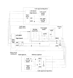
1 FIRST EMBODIMENT
2 Fig. 2 is a schematic diagram of a system for transmitting an audio
signal according to the
3 first embodiment of the present disclosure. As shown in Fig. 2, the
system comprises an audio
4 signal receiving device and an audio signal adapter device. The system is
configured to receive
an audio signal sent from an audio signal sending device via a headphone
interface, and to
6 transmit a signal to the audio signal sending device.
7 The audio signal sending device (such as a mobile communication terminal)
comprises: an
8 audio signal sending module, a MIC signal receiving module and a
headphone slot.
9 The headphone slot comprises: audio signal pins (such as a left-channel
pin and a
right-channel pin), a MIC pin and a ground pin (a reference signal pin of the
audio signal
11 sending end).
12 The audio signal sending module is connected with the audio signal pins
(such as the
13 left-channel pin and the right-channel pin) and the ground pin of the
headphone slot
14 respectively, and configured to output the audio signal via the audio
signal pin of the headphone
slot and the reference signal pin of the audio signal sending end.
16 The detailed structure and functions of the audio signal sending module
are known to those
17 skilled in the art, and will be omitted herein.
18 The MIC signal receiving module is connected with the MIC pin and the
ground pin of the
19 headphone slot, and configured to receive a MIC signal via the MIC pin
and the ground pin. and
to identify the signal according to a difference between voltages of the MIC
pin and the ground
21 pin.
22 The power supply module comprises a boosting transformer, a rectifier
and a filtering unit.
23 The detailed structure and functions of the MIC signal receiving module
are known to those
24 skilled in the art, and will be omitted herein.
The audio signal adapter device (such as an audio cable) comprises a headphone
plug, a
26 power supply module and a USB plug. Alternatively, the audio signal
adapter device may further
27 comprise a direct current isolating unit.
28 The headphone plug has an audio signal pin (such as a left-channel pin
and a right-channel
29 pin), a MIC pin and a ground pin.
The USB plug has a VBUS pin, a D+ pin, a D- pin and a ground pin.
9
22484332.1
CA 02839487 2013-12-16
CA Application
Bakes Ref 10798/00003
1 In this embodiment, the audio signal pin (the left-channel pin and/or the
right-channel pin)
2 of the headphone plug is connected with the D+ pin of the USB plug, and
the ground pin of the
3 headphone plug is connected with the D- pin of the USB plug.
4 Furthermore, the MIC pin of the headphone plug is connected with the
ground pin of the
USB plug.
6 The detailed functions and connection relationships between various units
in the power
7 supply module are described above, and will be omitted herein.
8 Alternatively, the MIC pin of the headphone plug may be connected with
the ground pin of
9 the USB plug via the direct current isolating unit; i.e. one end of the
direct current isolating unit
is connected with the MIC pin of the headphone plug, and the other end of the
direct current
11 isolating unit is connected with the ground pin of the USB plug for
isolating the direct current
12 level.
13 The audio signal receiving device comprises a USB slot, an audio
receiving module and a
14 signal sending module.
The USB slot has a VBUS pin, a D+ pin, a D- pin and a ground pin.
16 The VBUS pin in the USB slot is configured to supply power for the audio
signal receiving
17 device.
18 In this embodiment, the audio receiving module is connected with the Di"
pin and the D- pin
19 of the USB slot respectively, and the D+ pin and the D- pin of the USB
slot are used as an audio
signal pin of the headphone slot and a reference signal pin of the audio
signal receiving end
21 respectively to receive the audio signal,
22 Fig. 2a is a schematic diagram showing an audio signal receiving module
configured to
23 receive a differential signal
24 As shown in Fig. 2a, the above audio receiving module includes a
comparator. A positive
electrode and a negative electrode of the comparator are connected with the D+
pin and the D-
26 pin of the USB slot respectively, a ground pin of the comparator is
connected to ground, a power
27 pin of the comparator is connected with a power supply, an output pin of
the comparator is
28 configured to output a square wave corresponding to an input audio
signal.
29 The audio signal sending module can output a signal via one of the D+
pin and the D- pin
which is used as the reference signal pin,
22484332,1
CA 0283 9487 2013-12-16
CA Application
Blakes Ret 10798/00003
1 In this embodiment, the audio signal sending module is connected with the
D+ pin and the
2 D- pin of the USB slot, and may output the signal by varying the levels
both of D+ pin and D- pin
3 with the same amplitude simultaneously.
4 Furthermore, the audio signal sending module is further connected with
the ground pin of
the USB slot to keep a voltage of the ground pin of the USB slot at a preset
fixed voltage value.
6 It should be noted that, as the audio receiving module identifies the
audio signal according
7 to the difference between the voltages of the D+ pin and the D- pin of
the USB slot, in this
8 embodiment, when the signal sending module outputs a signal by varying
the levels both of the
9 D+ pin and the D- pin with the same amplitude simultaneously, the audio
signal receiving of the
audio receiving module will not be influenced. When it is not necessary to
consider whether the
11 receiving of the audio receiving module is influenced (for example, when
the audio receiving
12 module stops receiving the audio signal), the signal sending module can
output a signal
13 normally as long as it vary the level of the D- pin (the reference
signal pin of the audio signal
14 receiving end) and keeps the voltage of the ground pin at the preset
fixed voltage value.
SECOND EMBODIMENT
16 Fig. 3 is a schematic diagram of a system for transmitting an audio
signal according to the
17 second embodiment of the present disclosure. As shown in Fig. 3, the
differences between the
18 second embodiment and the first embodiment are as follows.
19 In the audio signal adapter device in the second embodiment, the audio
signal pin (the
left-channel pin and/or the right-channel pin) of the headphone interface end
(the headphone
21 plug) is connected with the D- pin of the USB interface end (USB plug),
and the ground pin of
22 the headphone plug is connected with the D+ pin of the USB plug.
23 Accordingly, in the audio signal receiving device in the second
embodiment, the audio
24 receiving module uses the D- pin and the D+ pin as the audio signal pin
of the headphone slot
and the reference signal pin of the audio signal receiving end respectively to
receive the audio
26 signal. When it is not necessary to consider whether the receiving of
the audio receiving module
27 is influenced, the audio signal sending module can output the signal
normally as long as it
28 varies the level of the D+ pin (the reference signal pin of the audio
signal receiving end).
29 Except for the above differences, the functions of various modules and
the connection
relationships between them in the second embodiment are the same as those in
the first
31 embodiment.
11
22484332.1
CA 0283 9 4 8 7 2013-12-16
CAApplication
Makes Ref 10798/00003
THIRD EMBODIMENT
2 Fig. 4 is a schematic diagram of a system for transmitting an audio
signal according to the
3 third embodiment of the present disclosure. As shown in Fig. 4, the
differences between the
4 third embodiment and the first embodiment are as follows.
One audio pin (such as the left-channel pin) of the headphone plug of the
audio signal
6 adapter device in Fig. 4 is connected with the primary coil pin of the
boosting transformer, and
7 the other audio pin (such as the right-channel pin) is only connected
with the D+ pin of the USB
8 plug.
9 In conclusion, when the audio signal sending device using such as the
headphone slot as
an interface is connected with the audio signal receiving device using such as
the USB socket
11 as the interface via the audio signal adapter device (the audio cable or
the audio adapter) of the
12 present disclosure, on one hand, the audio signal adapter device sends
the audio signal to the
13 audio signal receiving device via the D+ pin and the D- pin of the USB
interface end thereof and
14 supplies power to the audio signal receiving device via the VBUS pin and
the ground pin of the
USB interface end; on the other hand, the audio signal adapter device receives
the signal output
16 from the audio signal receiving device via the D- pin or the D+ pin of
the USB interface end, and
17 outputs the signal to the audio signal sending device via the ground pin
of the headphone
18 interface end. In other words, the audio signal adapter device according
to the present
19 disclosure can realize two-way adapter function between the headphone
interface device and
the USB interface device with a relatively low cost, and realize the power
supplying function to
21 supply power to the USB interface device, which extends the function of
the headphone
22 interface device and the USB interface device.
23 Furthermore, the audio signal receiving device with the USB interface,
used together with
24 the audio signal adapter device (the audio cable or the audio adapter)
of the present disclosure,
can realizes functions of getting power, receiving the audio signal and
sending a signal via the
26 four pins of the USB interface, without the need of increasing the
number of pins, thus reducing
27 the cost. Moreover, the audio signal receiving device with the USB
interface can output a signal
28 by varying levels both of D+ pin and D- pin with a same amplitude
simultaneously, without
29 influencing the audio signal receiving function.
Furthermore, the above loudspeaker interface may be fixed on the audio signal
sending
31 device.
12
22484332.1
CA 02839487 2013-12-16
CAApphcation
Blokes Ref: 10798/00003
1 The above loudspeaker interface may comprise a plurality of plugs, such
as an audio signal
2 plug comprising an audio signal input pin and a MIC plug comprising the
MIC pin.
3 Furthermore, the USB plug of the audio signal adapter device may be
replaced by the USB
4 slot (may be collectively referred to as the USB adapter interface).
Accordingly, the USB slot of
the audio signal receiving device may be replaced by the USB plug (may be
collectively referred
6 to as the USB interface).
7 As shown in Fig. 5, the interfaces used for connecting the audio signal
adapter device and
8 the audio signal receiving device of the present disclosure may be other
types of interface
9 having a power pin, an audio signal pin, a reference signal pin, and a
ground pin. The above
interface of the audio signal adapter device may be referred to as a adapter
end interface, and
11 the above interface of the audio signal receiving device may be referred
to as a receiving end
12 interface,
13 Those skilled in the art shall understand that all or parts of the steps
in the above
14 exemplifying method of the present disclosure may be achieved by
commanding the related
hardware with programs. The programs may be stored in a computer readable
storage medium,
16 and the programs comprise one or a combination of the steps in the
method embodiments of
17 the present disclosure when run on a computer.
18 In addition, each function cell of the embodiments of the present
disclosure may be
19 integrated in a processing module, or these cells may be separate
physical existence, or two or
more cells are integrated in a processing module. The integrated module may be
realized in a
21 form of hardware or in a form of software function modules. When the
integrated module is
22 realized in a form of software function module and is sold or used as a
standalone product, the
23 integrated module may be stored in a computer readable storage medium.
24 The storage medium mentioned above may be read-only memories, magnetic
disks or CD,
etc.
26 Although explanatory embodiments have been shown and described, it would
be
27 appreciated by those skilled in the art that the above embodiments
cannot be construed to limit
28 the present invention, and changes, alternatives, and modifications can
be made in the
29 embodiments without departing from spirit, principles and scope of the
present invention,
13
22484332.1