Note: Descriptions are shown in the official language in which they were submitted.
CA 02839586 2014-01-16
1 SEAMLESS UNDERMOUNT STAINLESS STEEL SINK SYSTEM
2
3 BACKGROUND OF THE INVENTION
4 Field of the Invention
The present invention is directed to a system comprising a
6 rimless stainless steel sink structured and disposed to be
7 undermounted to a solid countertop, such as granite or marble,
8 wherein an upper interface between the stainless steel sink and the
9 solid countertop comprises an upper seal which prevents water,
bacteria, or debris from entering between the rimless upper edge of
11 the stainless steel sink and the top surface of the solid
12 countertop. The present invention is further directed to a method
13 for seamless undermount installation of a stainless steel sink to a
14 solid countertop including but not limited to granite or marble.
16 DESCRIPTION OF THE RELATED ART
17 Stainless steel is the most popular sink style on the market
18 today. and provides a complementary match to many kitchen
19 appliances, such as, refrigerators, stoves, dishwashers, water
coolers, etc., which are also available in stainless steel or
21 stainless steel finish. Sinks made of stainless steel offer
22 numerous benefits including resistance to chipping, cracking or
23 peeling. Furthermore, stainless steel sinks will not rust or fade,
24 and they are easy to clean and maintain for a long periods of time
relative to other materials of construction.
1
CA 02839586 2014-01-16
1 There are different types and corresponding methods for
2 mounting stainless steel sinks to countertops. The most common and
3 traditional type is a topmount sink, such as is shown in Figure 1 -
4 PRIOR ART Topmount Sink. As is readily seen from Figure 1, a wide
flange extends completely around the topmount sink such that when
6 the topmount sink is positioned through a cut-out in a solid
7 material countertop, the flange rests on the top surface of the
8 countertop and is secured thereto via adhesives and/or mechanical
9 fasteners. As will be appreciated, however, the interface between
the flange and the top surface of the countertop provides a place
11 for water, moisture, bacteria, food, and other debris to accumulate
12 thereby creating a visually unappealing and potentially unsanitary
13 condition around the stainless steel sink.
14 Another common type of stainless steel sink for mounting to a
countertop is an undermount sink. An example of a PRIOR ART
16 Undermount Sink is illustrated in Figure 2. As shown in Figure 2,
17 the undermount sink comprises a much narrower flange which is
18 structured and disposed to enable the sink to be attached to the
19 bottom surface of a solid countertop below a sink cut-out
therethrough. More in particular, undermount sinks have flat rims
21 or flanges around the edges which may be glued and/or mechanically
22 mounted to the bottom surface of the countertop using mounting
23 clips and screws. The lip or sidewall of the sink cut out through
24 the solid countertop must be finished to match the top surface, as
it remains readily visible. Once again, however, and interface
2
CA 02839586 2014-01-16
1 exists at the bottom of the sink cut out and the top of the
2 undermount sink thereby allowing water, moisture, bacteria, food,
3 and other debris to accumulate, once again, creating a visually
4 unappealing and potentially unsanitary condition around the
stainless steel sink.
6 More recently, a so-called "Flush-Mount" sink has been
7 introduced to the market which has a much narrower and flatter rim
8 or flange around the top. These flush mount sinks are structured to
9 be mounted to a solid countertop through the top, wherein the
narrow flat rim or flange rests in an equally narrow and thin
11 recess cut into the solid countertop around the sink cut-out. As
12 such, the combination of the narrow flat flange and the recess cut
13 into the countertop serves to approximate a "flush-mount"
14 appearance. As will be appreciated by those of skill in the art,
however, considerable time, expense, expertise, and special
16 equipment are required in order to cut a recess into granite or
17 marble with the precision required to receive such a "flush-mount"
18 stainless steel sink and approximate a "flush-mount" appearance.
19 As such, it would be beneficial to provide a seamless
stainless steel sink system for installation to a solid material
21 countertop including, but not limited to, granite or marble, which
22 eliminates an interface where water, moisture, bacteria, food,
23 and/or other debris can accumulate and create unsightly and
24 unsanitary conditions. It would be further advantageous for such a
seamless stainless steel sink system to utilize standard
3
CA 02839586 2014-01-16
1 fabrication materials and techniques in order to provide an
2 economical alternative to the aforementioned "flush-mount"
3 stainless steel sinks systems. It would further be helpful for such
4 a seamless stainless steel sink system to accommodate a variety of
popular sink configurations including, but not limited to,
6 rectangular, oval, kidney shaped, etc. Another benefit may be
7 obtained by providing a stainless steel sink having a recessed
8 divider between bowls to allow for seamless undermount installation
9 of a stainless steel sink having more than one bowl.
11 SUMMARY OF THE INVENTION
12 The present invention is directed to a seamless undermount
13 stainless steel sink system. A seamless undermount stainless steel
14 sink system in accordance with the present invention comprises a
stainless steel sink and a solid countertop.
16 In at least one embodiment, the solid countertop comprises a
17 stone material of construction such as, but not limited to granite
18 or marble. The solid countertop has a top surface and a bottom
19 surface, wherein the top surface and the bottom surface at least
partially define a thickness therebetween, and in at least one
21 embodiment, the thickness of the solid countertop remains
22 substantially the same between the top surface and the bottom
23 surface. A sink mounting aperture is disposed through the solid
24 countertop, and the sink mounting aperture comprises an inner
periphery.
4
CA 02839586 2014-01-16
1 As previously stated, the present system further comprises a
2 stainless steel sink, and the stainless steel sink includes a
3 sidewall which partially forms at least one bowl. In at least eon
4 embodiment, the stainless steel sink comprises a plurality of bowls
separated from one another by a corresponding recessed divider, as
6 discussed in further detail below. A stainless steel sink in
7 accordance with the present invention further comprises a rimless
8 upper edge along and around the sidewall, and an outer periphery is
9 defined around the rimless upper edge.
The present seamless undermount stainless steel sink system
11 also includes a mounting assembly which is structured to securely
12 mount the stainless steel sink to the solid countertop. In one
13 embodiment, the mounting assembly comprises at least one mounting
14 bracket attached to a portion of the stainless steel sink at a
predetermined mounting depth below the rimless upper end of the
16 stainless steel sink, and in one further embodiment, the mounting
17 assembly comprises a plurality of mounting brackets each being
18 attached to a portion of the stainless steel sink, and each being
19 positioned at a predetermined mounting depth below the rimless
upper edge of the stainless steel sink.
21 A mounting bracket in accordance with one embodiment of the
22 present invention includes a sink flange, which is utilized to
23 attach the mounting flange to a portion of the stainless steel
24 sink, and a countertop flange to secure the stainless steel sing to
the solid countertop. In one embodiment, the countertop flange
5
CA 02839586 2014-01-16
1 includes a countertop flange surface which, in at least one
2 embodiment, is operatively disposed in a substantially
3 perpendicular orientation relative to the sidewall of the stainless
4 steel sink and is positioned at the predetermined mounting depth
below the rimless upper edge of the stainless steel sink.
6 An upper interface is formed between the outer periphery of
7 the stainless steel sink and the inner periphery of the solid
8 countertop and, in accordance with the present invention, an upper
9 seal is disposed in the upper interface between the rimless upper
edge of the stainless steel sink and the top surface of the solid
11 countertop. More importantly, the upper seal prevents water,
12 moisture, bacteria, food, or debris from entering between the
13 rimless upper edge of the stainless steel sink and the top surface
14 of the solid countertop.
The present invention is further directed to a method for
16 seamless undermount installation of a stainless steel sink to a
17 solid countertop, once again, including but not limited to granite
18 or marble.
19 In at least embodiment, the present method includes
fabricating a stainless steel sink with a rimless upper edge
21 defining an outer periphery therearound, such as may be
22 accomplished by hand fabrication. Of course, as most stainless
23 steel sinks manufactured today are drawn and comprise an upper
24 flange or lip. As such, in one embodiment, the present method
includes removing the mounting flange or lip from the stainless
6
CA 02839586 2014-01-16
1 steel sink in order to obtain a rimless upper edge.
2 The present method further includes preparing a mounting
3 template based on the outer periphery of the rimless upper edge of
4 the stainless steel sink, and creating a sink mounting aperture
through the solid countertop between a top surface and a bottom
6 surface based on the mounting template, wherein the sink mounting
7 aperture comprises an inner periphery configured to receive the
8 outer periphery of the rimless upper edge of the stainless steel
9 sink therethrough.
Next, one or more mounting brackets are positioned at a
11 predetermined mounting depth below the rimless upper edge of the
12 stainless steel sink, wherein each mounting bracket has a sink
13 flange and a countertop flange. In at least one embodiment, the
14 countertop flange comprises a countertop flange surface which is
positioned at the predetermined mounting depth below the rimless
16 upper edge of the stainless steel sink, and the present method
17 further includes attaching one mounting bracket to the stainless
18 steel sink.
19 Once the mounting bracket or plurality of mounting brackets
are positioned, and in at least one embodiment, attached to the
21 stainless steel sink, the rimless upper edge of the stainless steel
22 sink is positioned through the sink mounting aperture of the solid
23 countertop such that each countertop flange surface is adjacent to
24 the bottom surface of the solid countertop, and the stainless steel
sink is secured to the bottom surface of the solid countertop via
7
81776640
1 the at least one mounting bracket.
2 Finally, the present method includes applying an upper seal
3 along an upper interface between the outer periphery of the
4 rimless upper edge of the stainless steel sink and the inner
periphery of the sink mounting aperture through the solid
6 countertop, wherein the upper seal prevents water, moisture,
7 bacteria, and debris from entering between the rimless upper edge
8 of the stainless steel sink and the top surface of the solid
9 countertop.
In at least one embodiment, there is provided a seamless
11 undermount stainless steel sink system comprising: a solid
12 countertop having a top surface and a bottom surface, said top
13 surface and said bottom surface at least partially defining a
14 thickness therebetween, a sink mounting aperture disposed through
said solid countertop, said sink mounting aperture having an
16 inner periphery, a stainless steel sink comprising a sidewall
17 which partially forms at least one bowl, a rimless upper edge
18 along and around said sidewall of said stainless steel sink,
19 wherein an outer periphery is defined around said rimless upper
edge, said inner periphery of said sink mounting aperture
21 dimensioned to receive said outer periphery of said rimless upper
22 edge of said stainless steel sink therein such that said rimless
23 upper edge of said stainless steel sink is disposed adjacent and
24 substantially coplanar with said top surface of said solid
countertop when said stainless steel sink is mounted through said
8
CA 2839586 2019-02-28
81776640
1 bottom surface of said solid countertop, a mounting assembly
2 comprising at least one mounting bracket attached to a portion of
3 said stainless steel sink, said mounting bracket including a
4 countertop flange having a countertop flange surface, said
mounting bracket positioned a predetermined mounting depth below
6 said rimless upper edge of said stainless steel sink, an upper
7 interface formed between said outer periphery of said stainless
8 steel sink and said inner periphery of said solid countertop, and
9 an upper seal disposed in said upper interface between said
rimless upper edge of said stainless steel sink and said top
11 surface of said solid countertop.
12 In at least one embodiment, there is provided a method for
13 seamless undermount installation of a stainless steel sink to a
14 solid countertop, the method comprising: fabricating the
stainless steel sink with a rimless upper edge defining an outer
16 periphery therearound, preparing a mounting template based on the
17 outer periphery of the rimless upper edge of the stainless steel
18 sink, creating a sink mounting aperture through the solid
19 countertop between a top surface and a bottom surface based on
the mounting template, wherein the sink mounting aperture
21 comprises an inner periphery dimensioned to receive the outer
22 periphery of the rimless upper edge of the stainless steel sink
23 therein such that the rimless upper edge of the stainless steel
24 sink is disposed adjacent and substantially coplanar with the top
surface of the solid countertop when the stainless steel sink is
8a
CA 2839586 2019-02-28
81776640
1 mounted through the bottom surface of the solid countertop,
2 positioning at least one mounting bracket at a predetermined
3 mounting depth below the rimless upper edge of the stainless
4 steel sink, wherein the mounting bracket has a sink flange and a
countertop flange, the countertop flange comprising a countertop
6 flange surface which is positioned at the predetermined mounting
7 depth below the rimless upper edge of the stainless steel sink,
8 attaching the at least one mounting bracket to the stainless
9 steel sink, positioning the rimless upper edge of the stainless
steel sink through the sink mounting aperture of the solid
11 countertop such that the countertop flange surface is adjacent to
12 the bottom surface of the solid countertop, and the rimless upper
13 edge of the stainless steel sink is disposed adjacent and
14 substantially coplanar with the top surface of the solid
countertop when the stainless steel sink is mounted through the
16 bottom surface of the solid countertop, securing the stainless
17 steel sink to the bottom surface of the solid countertop via the
18 at least one mounting bracket, and applying an upper seal along
19 an upper interface between the outer periphery of the rimless
upper edge of the stainless steel sink and the inner periphery of
21 the sink mounting aperture through the solid countertop, wherein
22 the upper seal prevents water, moisture, bacteria, and debris
23 from entering between the rimless upper edge of the stainless
24 steel sink and the top surface of the solid countertop.
These and other objects, features and advantages of the
8b
CA 2839586 2019-02-28
81776640
1 present invention will become clearer when the drawings as well
2 as the detailed description are taken into consideration.
3 BRIEF DESCRIPTION OF THE DRAWINGS
4 For a fuller understanding of the nature of the present
invention, reference should be had to the following detailed
6 description taken in connection with the accompanying drawings in
7 which:
8 Figure 1 is a perspective view of a conventional PRIOR ART
9 topmount sink.
Figure 2 is a perspective view of a conventional PRIOR ART
11 undermount sink.
12 Figure 3 is a perspective view of one illustrative
13 embodiment of a stainless steel sink and mounting assembly in
14 accordance with the present invention for seamless undermount
installation to a solid countertop.
8c
CA 2839586 2019-02-28
CA 02839586 2014-01-16
1 Figure 4 is an exploded view of one illustrative embodiment of
2 a stainless steel sink, mounting assembly, and solid countertop in
3 accordance with at least one embodiment of the present invention.
4 Figure 5 is a perspective view of one illustrative embodiment
of a stainless steel sink mounted to a solid countertop in
6 accordance with the present invention.
7 Figure 6 is a partial cross-sectional view of one illustrative
8 embodiment of a stainless steel sink mounted to a solid countertop
9 in accordance with the present invention.
Figure 6A is a perspective view of one illustrative embodiment
11 of a mounting bracket in accordance with the present invention.
12 Figure 7 is a side elevation view of one illustrative
13 embodiment of a stainless steel sink in accordance with the present
14 invention prior to removal of a countertop flange.
Figure 7A is a side elevation view of the stainless steel sink
16 of Figure 5 after removal of the countertop flange.
17 Figure 8 is a block diagram illustrative of one method for
18 seamless undermount installation of a stainless steel sink to a
19 solid countertop in accordance with the present invention.
Like reference numerals refer to like parts throughout the
21 several views of the drawings.
22
23 DETAILED DESCRIPTION
24 As stated above, the present invention is directed to a
seamless undermount stainless steel sink system which is generally
9
CA 02839586 2014-01-16
1 shown as 10 throughout the figures. More in particular, and with
2 reference to Figure 5, the present system 10 comprises a solid
3 countertop 20 and a stainless steel sink 30. As is apparent from
4 Figure 5, an upper seal 54 between the solid countertop 20 and the
upper edge of the stainless steel sink 30 provides a virtually
6 seamless interface between the solid countertop 20 and the
7 stainless steel sink 30.
8 In at least one embodiment of the present system 10, a solid
9 countertop 20 is constructed from a solid material including, but
not limited to, granite, marble, limestone, quartz stone,
11 engineered stone, for example, acrylic and polyester composite
12 engineered stone, recycled glass, and hardwood.
13 As shown best in Figure 4, the solid countertop 20 in
14 accordance with at least one embodiment of the present invention
comprises a top surface 22 and a bottom surface 24. As Figure 4
16 further illustrates, the top surface 22 and bottom surface 24 at
17 least partially define a thickness 25 therebetween, which is
18 discussed in greater detail below with regard to the seamless
19 interface between the solid countertop 20 and the stainless steel
sink 30. Looking again to the illustrative embodiment of Figure 4,
21 the solid countertop 20 includes a sink mounting aperture 26
22 disposed therethrough. As will be appreciated by those skilled in
23 the art, the sink mounting aperture 26 may be created by cutting
24 through the solid countertop 20 in accordance with a template or
guide which is drawn, etched, or temporarily attached thereto. It
CA 02839586 2014-01-16
1 will be further appreciated that the sink mounting aperture 26 may
2 be formed via drilling and or sawing utilizing bits and/or blades
3 which are specifically designed for cutting through stone
4 materials, such as, once again, granite, marble, etc. Figure 4
further illustrates a solid countertop 20 in accordance with the
6 present invention wherein the sink mounting aperture 26 at least
7 partially defines an inner periphery 27 which extends along and
8 around the entire inner edge of the sink mounting aperture 26.
9 As previously stated above, a seamless undermount stainless
steel sink system 10 in accordance with the present invention
11 further comprises a stainless steel sink 30. It is understood to be
12 within the scope and intent of the present invention for a
13 stainless steel sink 30 to be constructed of any of a variety of
14 grades of stainless steel which are presently utilized for the
formation of sinks including, but not limited to, Type 304
16 stainless steel, Type 302 stainless steel, and Type 316 stainless
17 steel, as well as 200 series stainless steels, just to name a few.
18 It is further understood to be within the scope and intent of the
19 present invention to form a sink from other metals and metal alloys
besides stainless steel including, but once again, not limited to,
21 aluminum, brass, bronze, cast iron, copper, nickel, as well as from
22 non-metal materials such as terrazzo, glass, plastic, engineered
23 plastic and/or ceramic.
24 It will be further appreciated by those skilled in the art,
that the present seamless undermount stainless steel sink system 10
11
CA 02839586 2014-01-16
1 and installation methodology, which is discussed in greater detail
2 below, may also be utilized to install sinks formed of other metal
3 or metal alloy materials, and/or for undermount installation of a
4 sink to a solid countertop 20 wherein the solid countertop 20
comprises a stone material of construction including, but not
6 limited to, granite, marble, etc.
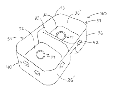
7 Figure 3 Is illustrative of one embodiment of a stainless
8 steel sink 30 in accordance with the present system 10. The
9 stainless steel sink 30 shown in the embodiment of Figure 3
comprises a plurality of bowls 32 which are separated by a recessed
11 divider 33. Figure 3 further illustrates that each bowl 32
12 comprises a drain 34 disposed through a bottom portion thereof.
13 Figure 4 is illustrative of another embodiment of a stainless steel
14 sink 30 in accordance with the present invention comprising a
single bowl 32 having a single drain 34 disposed therein.
16 Looking again to Figures 3 and 4, a stainless steel sink 30 in
17 accordance with the system 10 in accordance with present invention
18 comprises a sidewall 36 which at least partially defines the bowl
19 or bowls 32. As further illustrated in Figures 3 and 4, the
sidewall 36 comprises an inner wall 36' and an outer wall 36". As
21 may be seen best in Figures 3 and 4, a stainless steel sink 30 in
22 accordance with the present system 10 further comprises a rimless
23 upper edge 38 which extends around the entirety of the sidewall 36.
24 Similar to the inner periphery 27 along sink mounting aperture 26
of the solid countertop 20, a stainless steel sink 30 in accordance
12
CA 02839586 2014-01-16
1 with the present invention comprises an outer periphery 39 which
2 extends along and around the entirety of the sidewall 36 of the
3 stainless steel sink 30 proximate the rimless upper edge 38
4 thereof. As will be appreciated from the disclosure below, the
rimless upper edge 38 of the stainless steel sink 30 is required in
6 order to achieve the seamless undermount of the stainless steel
7 sink 30 to the solid countertop 20 in accordance with the present
8 system 10.
9 It will be understood and appreciated by those of skill in the
art that a stainless steel sink 30 may be fabricated by hand with a
11 rimless upper edge 38, however, mass production of stainless steel
12 sinks 30 commonly employs a process wherein a single piece of
13 stainless steel is drawn and formed into a sink 30 which includes a
14 mounting flange 35 extending around and along the upper portion of
a sidewall 36õ such as is shown in Figure 7. As such, and with
16 reference to Figures 7 and 7A, a seamless undermount stainless
17 steel sink system 10 in accordance with the present invention may
18 require removal of a mounting flange 35 from the sidewall 36 of
19 stainless steel sink 30 in order to obtain a rimless upper edge 38,
such as is shown in Figure 7A.
21 As will be appreciated from Figures 7 and 7A, and with
22 reference, by way of example, to the PRIOR ART sinks shown in
23 Figures 1 and 2, removal of the mounting flange 35 as shown in
24 Figures 7 and 7A from either of the PRIOR ART sinks shown in Figure
1 and 2 would result in the detachment of the separate bowls of the
13
CA 02839586 2014-01-16
1 PRIOR ART sinks from one another. As such, and as previously
2 disclosed with reference to Figure 3, a seamless undermount
3 stainless steel sink system 10 in accordance with at least one
4 embodiment of the present invention comprises a stainless steel
sink 30 having a recessed divider 33, specifically to permit a
6 mounting flange 35 from being removed such as is shown in Figures 7
7 and 7A, while maintaining a plurality of bowls 32 attached to one
8 another, once again, as shown in Figure 3.
9 As shown throughout the figures, a seamless undermount
stainless steel sink system 10 in accordance with the present
11 invention further comprises a mounting assembly generally shown as
12 40. A mounting assembly 40 comprises at least one mounting bracket
13 42, however, in at least one embodiment, a mounting assembly 40 in
14 accordance with the present system 10 comprises a plurality of
mounting brackets 42, such as is shown in the illustrative
16 embodiments of Figures 3 and 4. In at least one embodiment (not
17 shown), a single mounting bracket may be disposed around the
18 entirety of the sidewall 36 of the stainless steel sink 30 in
19 accordance with the present invention. By way of example, after
removal of a mounting flange 35 from a stainless steel sink 30, the
21 sink 30 is positioned through the top of the mounting flange 35 and
22 the mounting flange 35 is secured to the sidewalls 36, thus
23 providing a single mounting bracket 42 which extends along and
24 around the entire sidewall 36 of the stainless steel sink 30.
Alternatively, and again as shown in Figures 3 and 4, a
14
CA 02839586 2014-01-16
1 mounting assembly 40 comprises a plurality of mounting brackets 42
2 which are attached to an outer wall 36" of a sidewall 36 of a
3 stainless steel sink 30. More in particular, the plurality of
4 mounting brackets 42 are positioned in a spaced apart arrangement
around the sidewall 36 of the stainless steel sink 30, and are
6 attached thereto in order to provide a plurality of points for
7 securing the stainless steel sink 30 to the underside of a solid
8 countertop 20 along a bottom surface 24 thereof.
9 Figure 6A is illustrative of just one embodiment of a mounting
bracket 42 in accordance with the present invention. As shown in
11 the embodiment of Figure 6A, the mounting bracket 42 includes a
12 sink flange 43 which is disposed at a substantially right angle to
13 a countertop flange 44. Figure 6A further illustrates that a
14 countertop flange 44 comprises a countertop flange surface 45
which, as discussed in greater detail below, is positioned adjacent
16 to bottom surface 24 of the solid countertop 20 in order to secure
17 the stainless steel sink 30 to the solid countertop 20. In
18 addition, countertop flange 44, in at least one embodiment,
19 includes one or more countertop flange apertures 46 such as shown
again in Figure 6A. The countertop flange aperture(s) 46 facilitate
21 securing the mounting bracket 42 to the bottom surface 24 of the
22 solid countertop 20, as discussed in further detail below.
23 Figure 6 presents a partial cross-section view of one
24 illustrative embodiment of a stainless steel sink 30 seamlessly
mounted to a solid countertop 20 in accordance with the present
CA 02839586 2014-01-16
1 invention. As may be seen from Figure 6, a mounting bracket 42
2 comprises a sink flange 43 and a countertop flange 44 as previously
3 disclosed, wherein the sink flange 43 is attached to an outer wall
4 36" of the sidewall 36 via a sink interconnect 43'. It will be
appreciated by those of skill in the art that a sink interconnect
6 43' may comprise any of a variety of means for securely attaching a
7 sink flange 43 to the outer wall 36" of a stainless steel sink 30.
8 As one example, the sink interconnect 43' comprises a weld between
9 the sink flange 43 and the outer wall 36" of the sidewall 36. As
another example, an appropriate adhesive, such as, by way of
11 example only, an epoxy or a polyester resin, is utilized as sink
12 interconnect 43' in order to securely attach a sink flange 43 to
13 the outer wall 36" of the sidewall 36. In yet another embodiment,
14 the sink interconnect 43' comprises a mechanical fastener such as a
screw, a bolt, a rivet, etc., in order to securely attach the sink
16 flange 43 to the outer wall 36" of the stainless steel sink 30. It
17 will further be appreciated that a combination of one or more sink
18 interconnects 43' may be employed in order to further assure that
19 the sink flange 43 is securely attached to the stainless steel sink
30.
21 Similarly, a countertop interconnect 44' is utilized to
22 securely attach a countertop flange 44 to a portion of the bottom
23 surface 24 of the solid countertop 20. As before, with regard to
24 sink interconnect 43', the countertop interconnect 44' may comprise
any of a variety of appropriate attachment means. In at least one
16
CA 02839586 2014-01-16
1 embodiment, a countertop interconnect 44' comprises an epoxy resin
2 in order to securely attach the countertop flange 44 to the bottom
3 surface 24 the solid countertop 20, an in one further embodiment, a
4 two-part epoxy resin is utilized as a countertop interconnect 44'.
In such an embodiment, the epoxy resin is permitted to flow through
6 countertop flange aperture(s) 46 and onto the underside of the
7 countertop flange 44 to further facilitate securely attaching the
8 countertop flange 44 to the bottom surface 24 of the solid
9 countertop 20. In another embodiment, a mechanical fastener such as
a masonry screw may be utilized as a countertop interconnect 44' in
11 order to securely attach countertop flange 44 to the bottom surface
12 24 of the solid countertop 20. As will be appreciated by those
13 skilled in the art, a combination of an adhesive and a mechanical
14 fastener may be utilized as a countertop interconnect 44' in order
to further assure that the countertop flange 44 is securely
16 attached to the bottom surface 24 of the solid countertop 20.
17 In at least one alternate embodiment, mounting assembly 40 may
18 comprise a mounting clip 49 which is secured into the bottom
19 surface 24 of the solid countertop 20 via fastener 49'. As shown in
Figure 6, a portion of the mounting clip 49 extends over a portion
21 of the countertop flange 44 in order to further assure that the
22 countertop flange 44 remains securely attached to the bottom
23 surface 24 of the solid countertop 20.
24 With reference once again to Figure 4, each mounting bracket
42 is securely attached to the outer wall 36" of the stainless
17
CA 02839586 2014-01-16
1 steel sink 30 at a predetermined mounting depth 48. More in
2 particular, and again as shown in Figure 4, the countertop flange
3 surface 45 of each mounting bracket 42 is disposed at a
4 predetermined mounting depth 48 from the rimless upper edge 38 of
the stainless steel sink 30. More in particular, a predetermined
6 mounting depth 48 corresponds to the thickness 25 of the solid
7 countertop 20. Present industry standards dictate that slid granite
8 or marble countertops are provided with a thickness of either two
9 centimeters or three centimeters. In one embodiment, the countertop
flange surface 45 of the mounting bracket 42 is positioned at a
11 predetermined depth 48 of eighteen millimeters below the rimless
12 upper edge 38 of the stainless steel sink 30, for installation to a
13 standard two centimeter thick solid countertop 20. In an embodiment
14 of the present system 10 comprising a three centimeter thick solid
countertop 20, the countertop flange surface 45 of the mounting
16 bracket 42 is positioned at a predetermined depth 48 of twenty-
17 eight millimeters below the rimless upper edge 38 of the stainless
18 steel sink 30.
19 In at least one further embodiment, the predetermined mounting
depth 48 comprises a tolerance of plus or minus one millimeter
21 relative to the thickness 25 of the solid countertop 20. That is to
22 say, the predetermined mounting depth 48 at which the countertop
23 flange surface 45 is positioned below the rimless upper edge 38 of
24 the stainless steel sink 30 when the mounting flange is securely
attached to the outer wall 36" of the stainless steel sink 30 must
18
CA 02839586 2014-01-16
1 be no more nor no less than one millimeter of the thickness 25 of
2 the solid countertop 20. As such, when the stainless steel sink 30
3 is mounted to the solid countertop 20 from below, the rimless upper
4 edge 38 will be within one millimeter of the top surface 22 of the
solid countertop 20 which, as will be appreciated, permits the
6 seamless installation of stainless steel sink 30 in accordance with
7 the present system 10.
8 Furthermore, when the rimless upper edge 38 of a stainless
9 steel sink 30 is positioned through a sink mounting aperture 26 of
the solid countertop 20, an upper interface 52 is formed between
11 the inner periphery 27 of a sink mounting aperture 26 and the outer
12 periphery 39 along the rimless upper edge 38. In at least one
13 embodiment of the present invention, an upper interface tolerance
14 52' must be one millimeter or less. Stated otherwise, the distance
between the inner periphery 27 of a sink mounting aperture 26 and
16 outer periphery 39 along the rimless upper edge 38 is one
17 millimeter or less when a stainless steel sink 30 is mounted
18 through a sink mounting aperture 26 of a solid countertop 20 in
19 accordance with the present system 10.
Looking again to Figure 6, the seamless undermount stainless
21 steel sink system 10 in accordance with the present invention
22 further comprises a sealing assembly 50. The sealing assembly 50
23 includes an upper seal 54 which is applied along and around the
24 upper interface 52 between the inner periphery 27 of sink mounting
aperture 26 and the outer periphery 39 of the outer wall 36" of
19
CA 02839586 2014-01-16
1 the stainless steel sink 30. In one embodiment, the upper seal 54
2 comprises an epoxy glue or an epoxy resin which will securely bond
3 to both the solid countertop 20 and the stainless steel sink 30,
4 thereby providing an essential impervious seal over and along the
upper interface 52. In an alternate embodiment, the upper seal 54
6 comprises a polyester resin to securely bond to both the solid
7 countertop 20 and the stainless steel sink 30, once again,
8 providing an essential impervious seal over and along the upper
9 interface 52. In further embodiments, the upper seal 54 comprises a
polyester resin, a polyurethane resin, an epoxy resin, an acrylic
11 casting resin, or combinations thereof.
12 As
will be appreciated, the upper seal 54 will serve to
13 prevent water, moisture, bacteria, food, and/or other debris such
14 as may be encountered in a sink environment from entering into the
area between the solid countertop 20 and the stainless steel sink
16 30, in particular, into and through the upper interface 52
17 therebetween. In at least one further embodiment, a top coat 55 is
18 applied to the upper seal 54 wherein the top coat 55 is selected
19 based on the color of the top surface 22 of the solid countertop 20
so as to camouflage the presence of the upper seal 54. The top coat
21 55, in at least one embodiment, comprises a color matching epoxy or
22 polyester resin selected to simulate the color of the solid
23 countertop. In yet one further embodiment, the upper seal 54 and/or
24 top coat 55 may be further finished by sanding, buffing, etc., so
as to further camouflage the presence of the upper seal 54, thereby
CA 02839586 2014-01-16
1 enhancing the overall seamless appearance between stainless steel
2 sink 30 and the solid countertop 20 along the upper seal 54, such
3 as is shown best in Figure 5.
4 In at least one embodiment, a sealing assembly 50 in
accordance with the present invention further comprises a lower
6 seal 58, such as is shown in Figure 6. A lower seal 58 may comprise
7 a waterproof silicone adhesive material which is utilized to seal a
8 lower interface 56 between the outer wall 36" of the stainless
9 steel sink 30 and the bottom surface 24 of the solid countertop 20.
As previously indicated, the present invention further
11 comprises a method for seamless undermount installation of a
12 stainless steel sink to a solid countertop, which is shown as 100
13 in Figure 8. As shown in Figure 8, the present method 100 includes
14 fabricating a stainless steel sink with a rimless upper edge 110,
wherein the rimless upper edge at least partially defines an outer
16 periphery therearound. As previously stated, this may be
17 accomplished via hand fabrication techniques, wherein the sink as
18 fabricated is rimless. Alternatively, when a stainless steel sink
19 is fabricated by drawing and/or forming via mass production
techniques, a mounting flange must be removed from the top of the
21 sink, such as via cutting via mechanical of laser cutter equipment.
22 In at least one embodiment, fabricating a stainless steel sink
23 with a rimless upper edge 100 requires that the front and rear
24 sidewalls of the sink be essentially straight, with deviations long
the sidewalls of less than one-half millimeter inward or outward.
21
CA 02839586 2014-01-16
1 In addition, the rimless upper edge must not have deviations of
2 more than one millimeter along and around its entire length. That
3 is to say, if the sink is placed upside down on a completely flat
4 surface, there must not be more than a one millimeter gap between
the rimless upper edge of the sink and the flat surface at any
6 point between the upper edge and the surface.
7 The present method 100 further comprises preparing a mounting
8 template 120 based on the outer periphery of the rimless upper edge
9 of the stainless steel sink. The mounting template may be prepared
120 by turning the sink upside down on a template medium, such as
11 tracing paper, cardboard, etc. In at least one embodiment, the sink
12 may be placed upside down directly on the solid countertop itself,
13 and its outline traced directly thereon.
14 Once a mounting template has been applied to a surface of the
solid countertop, the present invention further provides for
16 creating a sink mounting aperture through the solid countertop 130,
17 wherein the mounting aperture extends between a top surface and a
18 bottom surface of the solid countertop based on the mounting
19 template. As previously noted above, in at least one embodiment the
sink mounting aperture comprises an inner periphery configured to
21 receive the outer periphery of the rimless upper edge of the
22 stainless steel sink therethrough.
23 After the sink mounting aperture is created through the solid
24 countertop, the present method includes positioning at least one
mounting bracket at a predetermined mounting depth 140 below the
22
CA 02839586 2014-01-16
1 rimless upper edge of the stainless steel sink. In at least one
2 embodiment, the mounting bracket has a sink flange and a countertop
3 flange, wherein the countertop flange comprises a countertop flange
4 surface which is positioned at the predetermined mounting depth
below the rimless upper edge of the stainless steel sink.
6 In at least one embodiment, the present method 100 comprises
7 attaching at least one mounting bracket to the stainless steel sink
8 150, and in one further embodiment, the present method comprises
9 attaching a plurality of mounting brackets to the stainless steel
sink 150, wherein each mounting bracket is positioned and attached
11 to the stainless steel sink at the predetermined mounting depth
12 below the rimless upper edge. A sink interconnect 43', such as
13 disclosed above, is utilized to securely attach the mounting
14 bracket(s) to the stainless steel sink, in accordance with one
embodiment of the present invention.
16 Once the mounting bracket(s) are securely attached to the
17 stainless steel sink at the predetermined mounting depth, the
18 method 100 of the present invention further comprises positioning
19 the rimless upper edge of the stainless steel sink through the sink
mounting aperture of the solid countertop 160, such that the
21 countertop flange surface is adjacent to the bottom surface of the
22 solid countertop. The present method 100 further provides for
23 securing the stainless steel sink to the bottom surface of the
24 solid countertop via at least one mounting bracket 170. Of course,
in one further embodiment of the present invention, the method 100
23
CA 02839586 2014-01-16
1 provides for securing the stainless steel sink to the bottom
2 surface of the solid countertop via a plurality of mounting
3 brackets 170. As before, a countertop interconnect 44', such as
4 disclosed above, is utilized to secure the stainless steel sink to
the solid countertop in accordance with at least one embodiment of
6 the present invention.
7 The present method for seamless undermount installation of a
8 stainless steel sink to a solid countertop 100 further comprises
9 applying an upper seal along an upper interface 180 between the
outer periphery of the rimless upper edge of the stainless steel
11 sink and the inner periphery of the sink mounting aperture through
12 the solid countertop. As noted above, in at least one embodiment,
13 the upper seal may comprise a polyester resin, and in one further
14 embodiment, the upper seal may comprise a color matched polyester
resin. In at least one embodiment, the upper seal prevents water,
16 moisture, bacteria, and debris from entering between the rimless
17 upper edge of the stainless steel sink and the top surface of the
18 solid countertop.
19 The top surface of the solid countertop may be masked around
the inner periphery of the sink mounting aperture prior to applying
21 the upper seal, so as to avoid unwanted application of the resin to
22 the countertop itself. In one further embodiment, a top coat is
23 applied to the upper seal in order to camouflage its presence, and
24 in one further embodiment, the upper seal may be finished, such as
via sanding, buffing, and/or polishing, so as to even further
24
CA 02839586 2014-01-16
1 conceal the presence of the upper seal at the seamless interface
2 between the stainless steel sink and the solid countertop.
3 In at least one further embodiment, the present method 100
4 includes applying a lower seal along a lower interface 180, wherein
the lower seal comprises a substantially waterproof material, such
6 as silicone, to prevent water or moisture from entering a lower
7 interface between the outer wall of the stainless steel sink and
8 the bottom surface of the solid countertop, as previously disclosed
9 hereinabove.
As will be appreciated from the foregoing, the present method
11 100 comprises steps which may be performed by different parties at
12 different locations. Specifically, steps 110 through 150 may be
13 performed at a factory which manufactures stainless steel sinks in
14 accordance with the present invention, while steps 160 through 180
may be performed by an individual or contractor who physically
16 installs a stainless sink manufactured in accordance with the
17 present invention in an end user's home or business.
18 Since many modifications, variations and changes in detail can
19 be made to the described embodiments of the invention, it is
intended that all matters in the foregoing description and shown in
21 the accompanying drawings be interpreted as illustrative and not in
22 a limiting sense. Thus, the scope of the invention should be
23 determined by the appended claims and their legal equivalents.
24 Now that the invention has been described,
25