Note: Descriptions are shown in the official language in which they were submitted.
CA 02839722 2013-12-17
WO 2013/009559
PCT/US2012/045515
METHOD AND APPARATUS FOR PRODUCING SYNTHESIS GAS
Field of the Invention
[0001] The present invention provides a method and apparatus for producing a
synthesis
gas product in which a hydrogen containing stream composed of a synthesis gas
preferably
containing no more than 20 percent by volume methane is reacted with oxygen
permeating
through an oxygen transport membrane to generate heat to heat the membrane and
support
endothermic heating requirements of steam methane reforming reactions
conducted in a
separate catalytic reactor designed to produce the synthesis gas product.
Background
[0002] Synthesis gas containing hydrogen and carbon monoxide is produced for a
variety
of industrial applications, for example, the production of hydrogen, chemicals
and
synthetic fuel production. Conventionally, the synthesis gas is produced in a
fired
reformer in which natural gas and steam is reformed to the synthesis gas in
catalyst filled
reformer tubes. The endothermic heating requirements for steam methane
reforming
reactions occurring within the reformer tubes are provided by burners firing
into the
furnace that are fueled by part of the natural gas. In order to increase the
hydrogen content
of the synthesis gas, the synthesis gas can be subjected to water-gas shift
reactions to react
residual steam in the synthesis gas with the carbon monoxide.
[0003] Such steam methane reformers are optimized for hydrogen production and
typically are fed with a reactant stream containing hydrocarbons and steam at
a steam-to-
carbon ratio of 1.5 to 3.5, depending on the quantity of carbon dioxide in the
reactant
stream, to thereby produce the synthesis gas at a hydrogen to carbon monoxide
ratio of 3
or higher. This is not optimal for the production of synthesis gas for
synthetic fuel
production such as in Fisher-Tropsch or methanol synthesis where the hydrogen
to carbon
monoxide ratio of 1.8 to 2.0 within the synthesis gas is more desirable.
Consequently,
where synthetic fuel production is a desired use of the synthesis gas, an
autothermal
reformer is typically used in which the steam-to-carbon ratio of the reactant
is typically
between 0.5 and 0.6. In such a reactor, oxygen is used to combust part of the
feed to
create additional steam and heat to reform the hydrocarbons contained in the
feed to the
1
CA 02839722 2013-12-17
WO 2013/009559
PCT/US2012/045515
synthesis gas. As such, for a large scale installation, an air separation
plant may be
required to supply the oxygen.
[0004] As can be appreciated, conventional methods of producing a synthesis
gas such as
have been discussed above are expensive and involve complex installations. In
order to
overcome the complexity and expense of such installations it has been proposed
to
generate the synthesis gas within reactors that utilize an oxygen transport
membrane to
supply oxygen and thereby generate the heat necessary to support endothermic
heating
requirements of the steam methane reforming reactions. A typical oxygen
transport
membrane has a dense layer that, while being impervious to air or other oxygen
containing
gas, will transport oxygen ions when subjected to an elevated operational
temperature and
a difference in oxygen partial pressure across the membrane. This difference
in oxygen
partial pressure can be produced by compressing the supplied air or from the
combustion
of hydrocarbons fed to a permeate side of the membrane and supported by
permeated
oxygen or a combination of the two methods.
[0005] For example, in US Patent Nos. 6,048,472 and US 6,110,979, a reactant
gas feed is
combined with steam. The reactant gas feed can be natural gas, naptha or other
hydrocarbon containing gas. This combined feed stream is then heated and
introduced
into an adiabatic pre-reformer to produce an intermediate stream that contains
carbon
monoxide, carbon dioxide, steam, hydrogen, and methane. The intermediate
stream can
be combined with carbon dioxide and steam. The resulting reactant stream is
then
introduced with air into reactant and oxidant sides, respectively, of an
oxygen transport
membrane reformer. The oxygen transport membrane reformer has an oxygen
transport
membrane separating the reactant and oxidant sides of the reformer. The
reactant gas
reacts with oxygen that has permeated through the oxygen transport membrane to
produce
a synthesis gas. Preferably a reforming catalyst is applied to at least a
portion of the
reactant side surface of oxygen transport membrane or packed into the reactant
side to
promote the reforming reactions.
[0006] US Patent No. 6,114,400 discloses an integrated system in which an
oxygen
transport membrane reformer is connected to a downstream reactor such as a
Fischer-
Tropsch reactor to produce a liquid product. In all of these patents the
presence of the pre-
reforming stage will prevent the breakdown of higher order hydrocarbons
present in the
2
CA 02839722 2013-12-17
WO 2013/009559
PCT/US2012/045515
reactant feed stream and the resulting carbon deposition that would otherwise
occur had
the higher order hydrocarbons been fed directly to the reactor. Such carbon
deposition
will degrade the reforming catalyst used in connection with the oxygen
transport
membrane reactor.
[0007] US Patent No. 6,296,686 discloses a reactor in which heat is supplied
to an
endothermic reforming reaction inside a reaction passage separated from an air
passage by
an oxygen transport membrane. A reactant gas, for example, methane flows
through the
reaction passage is combusted with permeated oxygen to provide the heat to
support the
reforming reaction. Further heat is supplied to the reforming reaction by
either
combusting a fuel with retentate or a fuel with a second permeate produced by
another
oxygen transport membrane or within a combustion passage. Alternatively, an
oxygen
transport membrane can be situated between an air passage and a combustion
passage and
a barrier is located between the combustion passage and the reaction passage.
In such case,
the oxygen transport membrane supplies oxygen permeate to support combustion
of a fuel
in the combustion passage and thereby generate heat that is transferred to the
reaction
passage.
[0008] US Patent Application Serial. No. 2008/0302013 discloses a staged
reactor system
having a sequential arrangement of reactor stages to produce a synthesis gas
product.
Each of the reactor stages has an oxidant side separated from a reactant side
by an oxygen
transport membrane. The reactant sides are linked together so that a reactant
stream
containing methane and steam is introduced into the system and sequentially
reacted with
oxygen permeating through the membrane to produce a synthesis gas product for
use in a
downstream reactor such as a Fischer-Tropsch reactor. Catalyst beds can be
located
within the reactant side of the reactor stages or can be positioned between
the reactor
stages. Both steam and a reactant gas from a downstream process utilizing the
synthesis
gas can be introduced into the feed between stages. The presence of the
multiple stages
allows the temperature within each of the reaction stages to be controlled to
prevent the
oxygen transport membrane from being degraded and to control the deposition of
soot
throughout the membrane system.
3
CA 02839722 2013-12-17
WO 2013/009559
PCT/US2012/045515
[0009] US Patent Application Serial No. 2006/0029539 discloses other examples
of staged
reactor systems that can employ oxygen transport membranes in which the air or
other
oxygen containing stream fed to each of the stages can be controlled to
control the
temperatures and conversation that can be obtained in producing a synthesis
gas.
[0010] The problem with all of the above-identified prior art systems is that
an oxygen
transport membrane will operate at high temperatures of about 900 C to 1100
C. Where
hydrocarbons such as methane and other higher order hydrocarbons are subjected
to such
temperatures carbon formation will occur. Additionally, where oxygen is
supplied by an
oxygen transport membrane directly to the reactor, the surface area of the
membrane is
distributed throughout the reactor. As such, the distribution of oxygen is non-
uniform
throughout the reactor. In other words, sufficient quantity of oxygen is not
generally
available at or near the entrance to the reactor. This also results in an
aggravated carbon
formation problem at the entrance that is especially the case at low steam-to-
carbon ratios.
In any case, a reactant containing methane and steam will produce a relatively
low oxygen
flux across the membrane resulting in the membrane area required for such a
reactor to be
larger and it will add to the expense and complexity in such a reactor or
system.
Additionally, a steam methane reforming catalyst must be periodically
replaced. In prior
art reactor designs where the catalyst is employed adjacent to the oxygen
transport
membrane, catalyst replacement becomes an expensive if not impractical
exercise.
[0011] The present invention, in one or more aspects, provides a method and
apparatus in
which the oxygen transport membrane is not directly used to react the steam
and methane
components of the reactant feed, but rather, to generate the heat required to
support
endothermic heating requirements of steam methane reforming reactions within a
separate
reactor, thus overcoming the above-identified problems.
4
CA 02839722 2013-12-17
WO 2013/009559
PCT/US2012/045515
Summary of the Invention
[0012] The present invention provides, in one aspect, a method for producing a
synthesis
gas product. In accordance with such method, permeate and retentate sides of
at least one
oxygen transport membrane element, configured to separate oxygen through
oxygen ion
transport, are contacted with a hydrogen containing stream formed from a
synthesis gas
preferably containing no more than 20 percent methane by volume, hydrogen and
an
oxygen containing stream, respectively. The hydrogen containing stream is
reacted with
the oxygen transported through the at least one oxygen transport membrane
element,
thereby generating heat, a heated reaction product stream, and a heated
retentate stream.
The heated reaction product stream is combined with a reactant stream to form
a combined
stream comprising hydrocarbons contributed by the reactant stream and steam
contributed
at least by the heated reaction product stream. The hydrocarbons and steam
contained in
the combined stream are reacted in at least one catalytic reactor to produce a
synthesis gas
stream. Heat generated by the at least one oxygen transport membrane element
to the at
least one catalytic reactor by radiation from the at least one oxygen
transport membrane
element and by indirect heat transfer from the heated retentate stream to the
at least one
catalytic reactor to assist in supporting endothermic heating requirements of
the steam
methane reforming reaction. The synthesis gas product is produced from at
least part of
the synthesis gas stream.
[0013] Unlike the prior art, the oxygen transport membrane is used to generate
heat and
potentially steam for the steam methane reforming and such heat is transferred
to a
separate catalytic reactor. A major advantage in such an arrangement is that
the
combustion of synthesis gas with permeated oxygen is a far more rapid reaction
than
methane or methane and higher order hydrocarbons. In the prior art, generally
a pre-
reformed stream that would be mostly methane and steam is combusted at the
permeate
side of an oxygen transport membrane that also contains a catalyst to promote
steam
methane reforming reactions. Consequently, a reactive system in accordance
with the
present invention may use far less oxygen transport membrane area than a prior
art reactor.
This translates into a reactive system in accordance with the present
invention that is less
complex and expensive than prior art systems and further, is less susceptible
to failure.
Additionally, since the catalytic reactor is a separate unit, the catalyst can
more easily be
CA 02839722 2013-12-17
WO 2013/009559
PCT/US2012/045515
replaced than in a prior art system in which the catalyst is incorporated into
an oxygen
transport membrane element.
[0014] A supplementary steam stream can be introduced into at least one of the
hydrogen
containing stream and the reactant stream. A carbon dioxide stream can be
introduced into
at least one of the heated reaction product stream, the reactant stream, the
hydrogen
containing stream and the combined stream to obtain some dry-reforming within
the
catalytic reactor. The oxygen containing stream can be preheated through
indirect heat
exchange with the heated retentate stream prior to being introduced to the
retentate side of
the at least one oxygen transport membrane. The synthesis gas stream can be
divided such
that the synthesis gas product is formed from part of the synthesis gas stream
and the
hydrogen containing stream is formed from another part of the synthesis gas
stream that is
recycled to the permeate side of the at least one oxygen transport membrane
element. The
synthesis gas stream can be cooled at least in part by adding water or steam
into the
synthesis gas stream prior to dividing the synthesis gas stream
[0015] A supplementary steam stream can be introduced into at least one of the
hydrogen
containing stream and the reactant stream. The at least one catalytic reactor
can have a
polishing section heated by an auxiliary burner fired by a fuel thereby
increasing the
equilibrium temperature at the outlet of the at least one catalytic reactor
and reducing
methane slip from such reactor or reactors. The heated retentate also supports
combustion
of the fuel within the auxiliary burner prior to preheating the oxygen
containing stream.
[0016] The at least one catalytic reactor can be at least one first catalytic
reactor. The
hydrogen containing stream is formed, at least in part, by reacting additional
hydrocarbons
and the further steam in the at least one second catalytic reactor. The heat
can also be
transferred to the second catalytic reactor by radiation and indirect heat
transfer from the
heated retentate stream to supply the endothermic heating requirements for the
reaction of
the additional hydrocarbons and further steam.
[0017] In another aspect, the present invention provides an apparatus for
producing a
synthesis gas product. Such apparatus comprises at least one oxygen transport
membrane element configured to separate oxygen from the oxygen containing
stream
contacting a retentate side of the at least one oxygen transport membrane
element and to
combust a hydrogen containing stream formed of a synthesis gas preferably
containing no
6
CA 02839722 2013-12-17
WO 2013/009559
PCT/US2012/045515
more than 20 percent methane at a permeate side of the at least one oxygen
transport
membrane element in the presence of permeated oxygen. This combustion
generates heat,
a heated reaction product stream and a heated retentate stream.
[0018] The at least one catalytic reactor is configured to react the
hydrocarbons and steam
to produce a synthesis gas stream and thereby to, at least in part, produce
the synthesis gas
product. The at least one catalytic reactor is connected to the at least one
oxygen transport
membrane element such that the heated reaction product stream is combined with
a
reactant stream containing the hydrocarbons to form a combined stream
comprising the
hydrocarbons contributed by the reactant stream and steam contributed at least
by the
heated reaction product stream that is introduced into the at least one
catalytic reactor.
The at least one oxygen transport membrane element and the at least one
catalytic reactor
are positioned with respect to one another within an elongated insulated
housing such that
the heat is radiated from the at least one oxygen transport membrane element
to the at least
one catalytic reactor and is indirectly transferred from the heated retentate
stream to the at
least one catalytic reactor to assist in supporting endothermic heating
requirements of the
steam methane reforming reaction.
[0019] The at least one oxygen separation element can also be in flow
communication
with the at least one catalytic reactor such that the synthesis gas product is
formed from a
first part of the synthesis gas stream and the hydrogen containing stream is
formed from a
second part of the synthesis gas stream. A means is provided for cooling the
synthesis gas
stream and for recycling the second part of the synthesis gas stream to the
permeate side of
the at least one oxygen transport membrane element.
[0020] The cooling and recycling means can comprise a convective heat exchange
network and a flow network. The convective heat exchange network has a series
of heat
exchangers in flow communication with the at least one catalytic reactor.
These heat
exchangers are configured to cool the synthesis gas stream through indirect
heat exchange
with: the second part of the synthesis gas stream; the reactant stream; a
hydrocarbon
containing stream containing the hydrocarbons; boiler feed water, thereby to
raise
superheated steam and a quench steam stream; and cooling water. The flow
network is
associated with the convective heat exchange network to introduce the quench
steam
stream into the synthesis gas stream prior to the series of heat exchangers,
to introduce at
7
CA 02839722 2013-12-17
WO 2013/009559
PCT/US2012/045515
least part of the superheated steam into the hydrocarbon containing stream
after having
been heated, thereby to form the reactant stream and to divide the synthesis
gas stream
after having indirectly exchanged heat with the hydrocarbon containing stream
and the
boiler feed water into the first and the second part of the synthesis gas
stream. Also
included is a recycle blower connected to the flow network to recycle the
second part of
the synthesis gas stream to the permeate side of the at least one oxygen
transport
membrane and a knockout drum connected to the convective heat exchange network
to
remove condensate from the synthesis gas stream after having been cooled,
thereby to
produce the synthesis gas product.
[0021] A heat exchanger can be connected to the oxygen separation device and
configured
such that the oxygen containing stream is preheated through indirect heat
exchange with
the heated retentate stream prior to being introduced to the retentate side of
the at least one
oxygen transport membrane element. The at least one catalytic reactor can have
a
polishing section situated within a duct that contains a burner fired by a
fuel thereby
increasing the equilibrium temperature at the outlet of the at least one
catalytic reactor and
reducing methane slip from such reactor or reactors. The duct burner is
positioned
between the oxygen separation device and the heat exchanger such that the
heated
retentate supports combustion of the fuel within the duct burner prior to
preheating the
oxygen containing stream within the heat exchanger.
[0022] In a specific embodiment of the present invention, the at least one
catalytic reactor
is at least one first catalytic reactor and at least one second catalytic
reactor is provided
that is configured to react additional hydrocarbons contained in a subsidiary
reactant
stream with further steam, thereby producing a subsidiary synthesis gas
stream. The
permeate side of the at least one oxygen transport membrane element is
connected to the at
least one second catalytic reactor such that the hydrogen containing stream is
formed, at
least in part, from the subsidiary synthesis gas stream. The at least one
second catalytic
reactor is positioned such that heat generated by the at least one oxygen
transport
membrane element is also transferred by radiation and through indirect heat
transfer from
the heated retentate stream to the at least one second catalytic reactor to
assist in
supporting endothermic heating requirements of the steam methane reforming
reaction.
8
CA 02839722 2013-12-17
WO 2013/009559
PCT/US2012/045515
[0023] The at least one oxygen transport membrane element can be of tubular
configuration and the permeate and retentate sides can be located on inner and
outer
surfaces of the at least one oxygen transport membrane element. The elongated,
insulated
reactor housing having opposed openings is situated at opposite ends houses
the oxygen
separation device and the at least one catalytic reactor such that the oxygen
containing
stream is introduced into one of the opposed openings and the heated retentate
stream is
discharged from the other of the opposed openings. The at least one catalytic
reactor faces
the at least one oxygen transport membrane element such that the heat is
radiated to the at
least one catalytic reactor and the oxygen containing stream contacts the
retentate side of
the at least one oxygen transport membrane and thereafter, the heated
retentate stream
contacts the at least one catalytic reactor to transfer heat from the heated
retentate stream
before being discharged from the other of the opposed openings. In an
embodiment of the
present invention where there is at least one second catalytic reactor, the at
least one
second catalytic reactor is positioned downstream of the at least one first
catalytic reactor
and also faces the at least one oxygen transport membrane element such that
the heat is
radiated to both the at least one first catalytic reactor and the at least one
second catalytic
reactor. Also, the oxygen containing stream contacts the retentate side of the
at least one
oxygen transport membrane element and thereafter, the heated retentate stream
contact the
at least one catalytic reactor and the at least one second catalytic reactor
to also transfer
the heat from the heated retentate stream to the at least one second catalytic
reactor before
being discharged from the other of the opposed openings.
[0024] In any embodiment of the present invention the at least one oxygen
transport
membrane element can be formed by a plurality of oxygen transport membrane
tubes and
the at least one catalytic reactor can be formed by reactor tubes containing a
catalyst to
promote the steam methane reforming reaction and having inlets at one end of
each of the
reactor tubes and outlets at the other end of the reactor tubes to discharge
the synthesis gas
stream. The plurality of oxygen transport membrane tubes and the reactor tubes
can be
contained within modules.
[0025]In one preferred embodiment the modules have the plurality of oxygen
transport
membrane tubes positioned so as to surround the central reactor tubes. Inlet
manifolds are
connected to the oxygen transport membrane tubes to introduce the hydrogen
containing
9
CA 02839722 2013-12-17
WO 2013/009559
PCT/US2012/045515
stream into the oxygen transport membrane tubes and outlet manifolds are
connected to
the oxygen transport membrane tubes to receive the heated combustion product
stream.
The outlet manifolds are connected to the inlets of the central reactor tubes
such that the
heated combustion product stream is combined with a hydrocarbon containing
stream,
thereby to form a combined stream to undergo the steam methane reforming
reaction. The
modules are arranged such that a view factor between each of the central
reformer tubes
and the oxygen transport membrane tubes radiating heat to each of the central
reformer
tubes is greater than or equal to 0.5
Brief Description of the Drawings
[0027] While the specification concludes with claims distinctly pointing out
the subject
matter that applicants regard as their invention, it is believed that the
invention will be
better understood when taken in connection with the accompanying drawings in
which:
[0028] Fig. 1 is a schematic illustration of an apparatus designed to carry
out a method in
accordance with the present invention;
[0029] Fig. 2 is a schematic illustration of an alternative embodiment of an
apparatus
designed to carry out a method in accordance with the present invention;
[0030] Fig. 3 is a fragmentary, schematic illustration of the apparatus of
Fig. 1 showing an
arrangement of oxygen transport membranes and catalytic reactors within an
elongated,
insulated housing;
[0031] Fig. 4 is a fragmentary, schematic illustration of the apparatus of
Fig. 2 showing an
arrangement of oxygen transport membranes and catalytic reactors within an
elongated,
insulated housing;
[0032] Fig. 5 is an alternative embodiment of Fig. 3;
[0033] Fig. 6 is a perspective view of a module in accordance with the present
invention
that incorporates oxygen transport membrane tubes and a central reactor tube
in an
advantageous heat transfer integration;
[0034] Fig. 7 is a perspective view of a sub-assembly of oxygen transport
membranes
used in the module shown in Fig. 6;
[0035] Fig. 8 is a bottom perspective view of a plate-like element utilized in
the module
shown in Fig. 6;
CA 02839722 2013-12-17
WO 2013/009559
PCT/US2012/045515
[0036] Fig. 9 is a top perspective view of a first plate used in the plate-
like element shown
in fig. 8;
[0037] Fig. 10 is a fragmentary, perspective view of Fig. 6 with portions
broken away to
show internal features of the module of Fig. 6; and
[0038] Fig. 11 is a schematic, sectional illustration of an arrangement of
reactor modules
shown in Fig 6 employed in an elongated insulated reactor housing shown in
Fig. 3.
[0039] For the sake of avoiding repetition, common elements in the various
Figures utilize
the same numbers where the explanation of such elements would not change from
Figure
to Figure.
Detailed Description
[0040] With reference to Figure 1, an apparatus 1 is illustrated that is
designed to produce
a synthesis gas product through the steam methane reforming of hydrocarbons.
Apparatus
1 includes one or more oxygen transport membrane elements of which oxygen
transport
membrane element 2 is illustrated. Oxygen transport membrane element 2
supplies heat
by radiation and convective heat transfer to supply the endothermic heating
requirements
of a catalytic reactor 3 within which the hydrocarbons and steam are reacted
to produce a
synthesis gas. As well known in the art, at high temperatures, from 700 to
11000 C, steam
will react with methane to yield a synthesis gas that contains hydrogen and
carbon
monoxide. Catalytic reactor 3, as would be known in the art, contains a
catalyst, typically
nickel, to promote such steam methane reforming reaction. Additionally, water-
gas shift
reactions occur in which the carbon monoxide will react with the steam to
produce carbon
dioxide and hydrogen. Although the water-gas shift reaction is exothermic, the
steam
methane reforming reaction is endothermic and requires heat to be supplied to
the catalytic
reactor. Carbon dioxide will also react with methane in so-called dry
reforming reactions
to also produce the synthesis gas. In this regard, carbon dioxide can be added
for such
purpose. The resulting synthesis gas is a mixture of hydrogen, carbon
monoxide, carbon
dioxide and water and other known constituents such as unreacted methane known
in the
art as methane slip. The synthesis gas is optionally cooled and compressed
within a
convective section 4 to produce the synthesis gas product and a recycle stream
that is fed
11
CA 02839722 2013-12-17
WO 2013/009559
PCT/US2012/045515
back to the oxygen transport membrane device 2 for combustion with permeated
oxygen
to generate the necessary heat.
[0041] As is apparent from the above discussion, apparatus 1 functions in an
analogous
manner to an autothermal reformer in which oxygen is added to the reactant to
partially
oxidize some of the hydrocarbons contained in the reactant to generate the
heat to support
the overall endothermic heating requirements for the steam methane reformer.
This being
said, the combustion occurring within the oxygen transport membrane device 2
will
typically be at least 50 percent complete so that there is virtually no
molecular oxygen that
will be left over to react with the hydrocarbons because otherwise sufficient
heat will not
be generated by the oxygen transport membrane device 2 to support endothermic
heating
requirements required for the steam methane reforming reactions occurring
within the
catalytic reactor 3. A further point to be mentioned, is that if an operation
were attempted
within apparatus 1 in which the hydrocarbons contained within reactant were
combusted
within the oxygen transport membrane device 2, such a reaction will typically
be so slow
that it is impractical if not impossible to generate the heat required for
subsequent
endothermic steam methane reforming because the hydrocarbons will not react to
an
appreciable extent within an oxygen transport membrane. The present invention
takes
advantage of the fact that oxidation of hydrogen and carbon monoxide is a
particularly
rapid reaction that part of the synthesis gas generated from the catalytic
reactor can be
used to generate heat while still allowing for a reasonable production rate of
the synthesis
gas product from apparatus 1.
[0042] More specifically, an oxygen containing stream 10 can be introduced by
means of
a blower 14 into a heat exchanger 12 for purposes of preheating the oxygen
containing
stream 10. Heat exchanger 12 could be a convective type heat exchanger or a
high
efficiency, cyclic regenerative type heat exchanger. Oxygen containing stream
10 can be
ambient air or possibly a stream bled from a compressor section of a gas
turbine. In the
latter case, blower 14 and heat exchanger 12 might not be necessary. It is to
be noted that
no compression of the oxygen containing stream 10 is required or even desired.
The
blower 14 is provided to simply motivate the oxygen containing stream 10
through
apparatus 1 against pressure drops produced by piping and the like. The heated
oxygen
containing stream 10 is then contacted with the retentate side 16 of oxygen
transport
12
CA 02839722 2013-12-17
WO 2013/009559
PCT/US2012/045515
membrane element 18 incorporated into the oxygen transport membrane device 2.
Although one such oxygen transport membrane element 18 is illustrated, as
would occur
to those skilled in the art, there could be many of such elements in an
industrial application
of the present invention and the oxygen transport membrane device 2 could be
oxygen
transport membrane tubes 122 incorporated into a module 120 to be discussed
hereinafter.
As will also be discussed, the oxygen transport membrane element 18 is formed
of a
ceramic capable of conducting oxygen ions at an elevated operational
temperature. The
oxygen ions permeate through the oxygen transport membrane element 18 in the
direction
of arrowhead 20 to the permeate side 22 of the oxygen transport membrane
element 18.
[0043] As a result of the separation of the oxygen and combustion occurring at
the
permeate side 22 of oxygen transport membrane element 18, a heated retentate
stream 24
is formed that, after transferring heat to catalytic reactor 3, can optionally
can be
introduced into a duct burner 26 and used to support combustion of a fuel
stream 28 to
produce a heated flue gas stream 30 that is introduced into the heat exchanger
12 for
purposes of preheating the oxygen containing stream 10 through indirect heat
exchange.
The resulting cooled flue gas stream 32 is discharged from heat exchanger 12.
Although
not illustrated, if necessary, supplemental air can be injected into duct
burner 26 to support
combustion. It is to be noted that embodiments are possible in which duct
burner 26 is not
used and the retentate stream is directly introduced into the heat exchanger
12 for purposes
of pre-heating the oxygen containing stream 10. In this regard, oxygen
containing stream
could contact retentate side 16 of oxygen transport membrane 18 at ambient
temperature and without preheating. However, this would not be thermally
efficient.
[0044] A hydrogen containing stream 34 is introduced into the permeate side 22
of the
oxygen transport membrane element 18 that is oxidized though combustion of
permeated
oxygen to produce a heated combustion product stream 36. The heated combustion
product stream 36 is combined with a reactant stream 38 to produce a combined
stream 40
that contains steam and hydrocarbons that is introduced into the catalytic
reactor 3 where
such stream is subjected to steam methane reforming reactions to produce a
synthesis gas
stream 42. It is to be noted that embodiments of the present invention are
possible in
which the reactant stream only contains hydrocarbons such as methane and lower
order
alkanes and the steam is contributed solely by the heat combustion product
stream. As
13
CA 02839722 2013-12-17
WO 2013/009559
PCT/US2012/045515
will be discussed, however, it is preferable, however, that steam be added to
both the
reactant stream 38, the heated combustion product stream 42 and the hydrogen
containing
stream 34. Further, as illustrated, a carbon dioxide stream 39 may optionally
be added to
the reactant stream 38 or the combined stream 40 or the heated combustion
product stream
36 or possibly the hydrogen containing stream 34 as a stream 81, upstream of
heat
exchanger 46 for purposes of enhancing dry reforming occurring within
catalytic reactor 3.
[0045] The combustion of the hydrogen containing stream 34 produces heat that
through
radiation as generally indicted by arrowheads 41 which together with the
convective heat
transfer provided by heated retentate stream 24 contacting the catalytic
reactor 3, heats the
catalytic reactor 3 to at least assist in supplying endothermic heating
requirements of the
steam methane reforming reactions occurring in catalytic reactor 3. If
necessary,
endothermic heating requirements can also be supplied through indirect heating
with the
use of auxiliary burners combusting part of the reactant stream 38 and firing
at the
catalytic reactor 3.
[0046] Synthesis gas stream 42 contains hydrogen, carbon monoxide, steam and
carbon
dioxide and as discussed above, other components such as possible methane
slip.
Convective section 4 is designed to cool the synthesis gas stream 42 and
recycle part of
the synthesis gas stream to form the hydrogen containing stream 34.
Practically, it is
necessary to cool the synthesis gas stream 42 before recycling such stream in
a recycle
blower 78. Convective section 4 is also designed such that in cooling the
synthesis gas
stream, various feed streams are preheated and process steam is generated.
[0047] In the cooling of synthesis gas stream 42, a steam stream 43 is
combined within the
synthesis gas stream 42 to produce a quenched synthesis gas stream 44.
Alternatively,
water could also be added to synthesis gas stream 42 to add steam to the
process and also
increase the temperature reduction due to the latent heat of vaporization for
the added
water. This step is important not only to cool the synthesis gas stream 42,
but also to
prevent coking of the synthesis gas upon cool down.
[0048] The quenched synthesis gas stream 44 is successively further cooled in
a
convective heat exchange network that includes heat exchangers 46, 48, 50, 52,
54 and 56
and water cooled heat exchangers 58 and 64. The quenched synthesis gas stream
44 after
having been cooled in water cooled heat exchanger 58 by a cooling water stream
59, is
14
CA 02839722 2013-12-17
WO 2013/009559
PCT/US2012/045515
divided into a first part 60 and a second part 62. First part 60 is further
cooled within the
water cooled heat exchanger 64 by cooling water stream 66 and the resulting
stream is
introduced into a knock-out drum 68 from which a condensate stream 70 is
drained to
produce a cooled synthesis gas stream 72. Cooled synthesis gas stream 72 is
optionally
compressed in a compressor 74 to produce a synthesis gas product stream 76
that forms
the synthesis gas product. The second part 62 is recirculated back to the
permeate side 22
of the oxygen transport membrane element 18 by means of a recirculation blower
78.
Optionally, a first supplementary steam stream 80 is added to the second part
62 to form
the hydrogen containing stream 34 that is preheated within heat exchanger 46
through
indirect heat exchange with the quenched synthesis gas stream 44.
[0049] A hydrocarbon containing stream 82, that can be natural gas and more
preferably,
natural gas that has been pre-reformed in an adiabatic pre-reformer, is
compressed in a
feed compressor 84 and then preheated in heat exchanger 50 that serves as a
fuel preheater.
It is to be mentioned that where natural gas is used, it will typically
contain unacceptably
high level of sulfur species. While there are sulfur tolerant catalysts that
can be used in
catalytic reactor 3, in most cases the natural gas would have to be
hydrotreated to remove
the sulfur content. Further, since natural gas contains alkenes that will
break down at high
temperature to form carbon that can deactivate the catalyst, the steam to
carbon ratio of the
stream entering catalytic reactor 3 would have to be carefully controlled to
prevent coking
of the catalyst. In this regard, other possible hydrocarbon containing feeds
include
associated gas, LPG, naptha. The resulting heated stream can be combined with
a second
supplementary steam stream 86 to form the reactant stream 38 that is further
heated in heat
exchanger 48 through indirect heat exchange with the quenched synthesis gas
stream 44
after having passed through heat exchanger 46. The first and second
supplementary steam
streams 80 and 86 are formed by pumping a boiler feed water stream 88 in a
feed water
pump 90 and then passing the pressurized stream through heat exchanger 56 that
acts as a
boiler feed water heater and then through heat exchanger 54 that serves as a
boiler to
create saturated steam and finally through a heat exchanger 52 that serves as
a super heater
to produce a superheated steam stream. One portion of the saturated steam
stream 92
forms steam stream 43 and the other portion passes through heat exchanger 52
and is
CA 02839722 2013-12-17
WO 2013/009559
PCT/US2012/045515
superheated and then, subsequently divided into the first and second
supplementary steams
streams 80 and 86.
[0050] As can be appreciated, in possible applications of the present
invention, convective
section 4 may not be present where the synthesis gas is desired at high
temperature.
Further, convective section 4 could be simplified by providing appropriate
means to cool
the synthesis gas before recycling part of the same back to the permeate side
22 of the
oxygen transport membrane. For example, the use of water cooled heat
exchangers alone
or preferably in combination with steam stream 43 or other quench stream.
[0051] With reference to Figure 2, an alternative embodiment of the apparatus
shown in
Figure 1 is indicated as apparatus 1'. In apparatus l', a hydrogen containing
stream 34' is
produced by reacting a subsidiary reactant stream 100 in a reactor 3'.
Subsidiary reactant
stream could be a stream containing steam and fuel in a higher net steam-to-
carbon ratio
than the reactant stream 38 fed into catalytic reactor 3. Reactor 3' would be
a catalytic
reactor designed to react the hydrocarbons and steam to a sufficient extent
that the
hydrogen containing stream 34' is a synthesis gas that preferably contains
methane present
in an amount of no greater than 20 percent by volume. For example, the fuel
could be pre-
reformed natural gas having a methane content of 80% or greater, that is
reacted with
steam to reduce the methane content to below 20 percent by volume.
[0052] Reactor 3' could be thermally integrated with the oxygen transport
membrane
element 2 and as such, heat is radiated from the oxygen transport membrane
element 2 to
both the reactor 3 and the reactor 3' as indicated by arrowheads 41a and 41b,
respectively.
Further, convective heat transfer occurs through indirect heat transfer
produced by contact
of the heated retentate stream 24 with both the catalytic reactor 3 and 3'.
However,
embodiments of the present invention are possible in which reactor 3' are not
be thermally
integrated with reactor 3. Synthesis gas stream 42 can then be further
processed in
convective system 4 or potentially could be used in a process that required
the synthesis
gas stream 42 at high temperature. In most cases, however, a water stream or
steam
stream 43 would be introduced into synthesis gas stream 42 for purposes of
lowering the
temperature of such stream. Additionally, it is also possible to integrate the
apparatus l'
with recirculation of part of the synthesis gas produced by reactor 3 by the
use, for
example, of a convective system such as convective system 4. It is also to be
noted that
16
CA 02839722 2013-12-17
WO 2013/009559
PCT/US2012/045515
where there exists a suitable hydrogen containing stream 34', such as a
hydrogen product
stream from a conventional steam methane reformer, the same could be
introduced into
the permeate side 22 of an oxygen transport membrane element 2 without the use
of
reactor 3' and subsidiary reactant stream 3'. However, as indicated above, the
hydrogen
containing stream 34 or 34' or any hydrogen containing stream used for such
purpose is a
synthesis gas that has been sufficiently processed so as to preferably contain
no more than
20 percent methane by volume. Any increase in methane beyond this point is
disadvantageous because it does not react at high rates relative to hydrogen
and carbon-
monoxide, and this will generally result in reduced overall oxygen transport.
Additionally,
issues with coking may be present.
[0052] As has been discussed above, the hydrogen to carbon ratio of the
synthesis gas
product produced by apparatus 1 or apparatus l' for that matter, is the
central object of the
control for of such apparatus. For instance, a hydrogen to carbon ratio of
about 2.0 in the
synthesis gas product is required for direct integration with a Fisher-Tropsch
gas to liquid
plant. There are 3 control handles that will affect the hydrogen-to-carbon
ratio of the
process and apparatus as has been discussed above. Assuming fixed carbon input
and
hydrogen input from fuel, input steam, input oxygen, and input carbon (not in
fuel) can be
adjusted to in turn control the hydrogen-to-carbon ratio in the synthesis gas
product. Steam
may be added anywhere in either apparatus 1 or 1'. This steam provides
additional
hydrogen to the process and thus, minimizing steam reduces hydrogen to carbon
ratio of
the synthesis gas product. Oxygen is input through steam, carbon dioxide and
as
molecules transferred across the oxygen transport membrane 18. Oxygen input
from these
sources, excepting steam, will generally reduce hydrogen-to-carbon monoxide
ratio of the
synthesis gas product. Hydrogen input is from steam and hydrogen contained in
the
reactant stream 38. Decreasing steam and decreasing hydrogen-to-carbon ratio
of the fuel
(increasing carbon content) will reduce hydrogen-to carbon monoxide ratio of
the
synthesis gas product.
[0053] The process design incorporated into apparatus 1 or l' allows the steam
input to be
reduced while maintaining margin on coke formation within the process. If
carbon
content can be increased in the reactant stream 38, then hydrogen-to-carbon
monoxide
may be reduced further. The reactant stream 38, as discussed above, is
generally
17
CA 02839722 2013-12-17
WO 2013/009559
PCT/US2012/045515
comprised of steam and pre-reformed natural gas. A carbon containing gas
stream, for
instance, stream 39, may be combined with the reactant stream 38 to reduce
hydrogen-to-
carbon ratio of the reactant stream 38. Carbon dioxide input at the reactant
stream is
particularly valuable in reducing the hydrogen to carbon ratio in the
synthesis gas product.
Stream 39 may be a carbon dioxide rich tail gas generated from the process, or
can be
recycled, or a carbon-dioxide rich gas imported from a nearby process. Having
said this,
however, the present invention is equally applicable where hydrogen is the
desired product
and therefore, the hydrogen to carbon ratio is optimized for such purpose.
[0054] With reference again to Figure 1 and with additional reference to
Figure 3, the
thermal integration of oxygen transport membrane element 2 and reactor 3 can
be
accomplished in an elongated insulated reactor housing 110 that is provided
with opposed
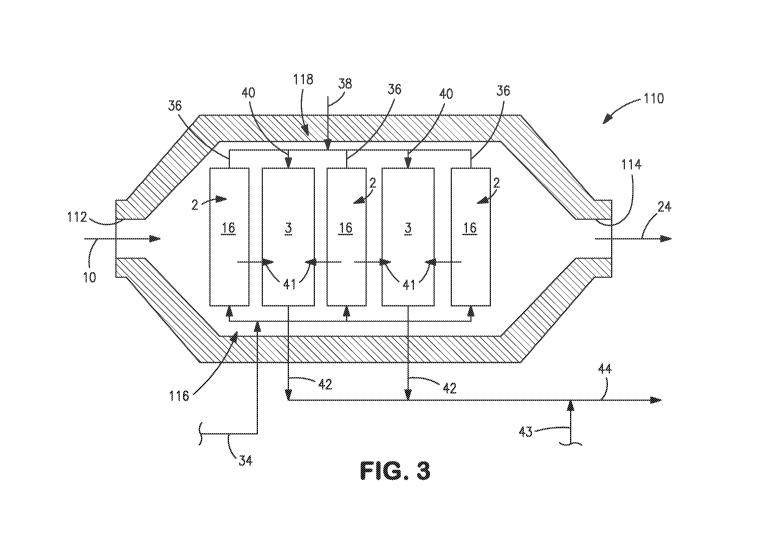
openings 112 and 114 provided within opposite ends thereof Elongated insulated
reactor
housing 110 houses the oxygen transport membrane element 2 and the catalytic
reactor 3
so that they face one another for purposes of radiation heat transfer and also
to allow the
heated retentate stream 24 to contact the catalytic reactor 3. A manifold 116
is provided
for introduction of hydrogen containing stream 34 into the permeate sides 22
of the
oxygen transport membrane elements 2. A manifold 118 is provided for combining
the
heated combustion product stream 36 from the permeate side 22 with the
reactant stream
38 and thereby form the combined stream 40 for introduction into the catalytic
reactors 3.
In Figure 3, although three such oxygen transport membrane elements 2 and
reactors 3 are
illustrated, as mentioned above, there could be many more of such elements and
reactors
depending upon the industrial need. However, preferably, the oxygen transport
membrane
elements 2 are all in the form of a tube in which the permeate side 22 is
located inside the
tube and the retentate side 16 is the outer surface of the tube. As will be
discussed, such
tubes can be of cylindrical form, although hollow plate-like elements are
possible.
[0055] Although it is possible to conduct a process in accordance with the
present
invention in which the retentate and permeate sides of the oxygen transport
membrane
elements are reversed, this would be disadvantageous in that it would be very
difficult to
completely combust the synthesis gas and would require that the elongated
insulated
reactor housing 110 to be a pressure vessel. Further, it is also possible to
conduct a
process of the present invention in which the oxygen containing stream 10 was
18
CA 02839722 2013-12-17
WO 2013/009559
PCT/US2012/045515
compressed to provide part of the driving force for the oxygen separation.
This would not
be desirable because it would also require the elongated insulated reactor
housing 110 to
be a pressure vessel. In this regard, the illustrated elongated insulated
reactor housing 110
is designed to operate at atmospheric pressure and as such, is not a pressure
vessel.
[0056] In this illustrated embodiment, the oxygen containing stream 10 is
introduced into
opening 112 and the heated retentate stream is discharged from opening 114. In
operation,
the oxygen containing stream 10 contacts the retentate side 16 of the oxygen
transport
membrane elements 2 and becomes successively lean in oxygen as oxygen
permeates to
the permeate side 22 of such elements. As the hydrogen containing stream 34
reacts with
the permeated oxygen, the resulting retentate stream becomes successively
heated to
indirectly transfer the heat generated by the oxygen transport membrane
elements to the
catalytic reactors 3. At the same time, the oxygen transport membrane elements
2 also
radiate heat to also supply heat to the catalytic reactors 3. In fact, such
radiation
preferably constitutes approximately 80 percent of the heat transferred. Thus,
the heat
transferred as indicated by arrowheads 41 from the oxygen transport membrane
elements 2
to the catalytic reactors 3 is accomplished by both radiation and convection.
While, there
is also some heat transferred directly, through the mixing of the heated
combustion
product stream 36 with reactant stream 38, this heat transfer is much less
than the radiation
and convective heat transfer discussed above. In fact, its importance will be
negligible in
the illustrated embodiment given the preheating of the reactant stream 38.
[0057] With reference again to Figure 2 and with additional reference to
Figure 4, the
integration of catalytic reactors 3 and 3' and oxygen transport membrane
elements 2 is
illustrated in an elongated insulated reactor housing 110' that functions in
much the same
manner as elongated insulted reactor housing 110. The major difference is that
at least
one of the catalytic reactors 3 has been replaced by a catalytic reactor 3'
that is connected
to the oxygen transport membrane elements 2 by an manifold 116' for
introduction of the
hydrogen containing stream 34' into the permeate side 22 thereof. The
catalytic reactor 3'
is positioned so as also to be heated by radiation heat transfer as shown by
arrowhead 42b
from at least one of the oxygen transport membrane elements 16 and also, to be
heated
through indirect heat transfer from the heated retentate after the heated
retentate has heated
the catalytic reactors 3.
19
CA 02839722 2013-12-17
WO 2013/009559
PCT/US2012/045515
[0058] With reference to Figure 5, an elongated insulated reactor housing 110"
is
illustrated that is connected to a duct burner housing 112 by means of an
insulated transfer
section 114. Elongated, insulated reactor housing 110" functions in the same
manner as
elongated insulated reactor housing 110. In this regard, the oxygen transport
membrane
elements 2 transfer heat by radiation and conduction to catalytic reactors 3'.
As is
apparent, however, catalytic reactors 3' are longer than catalytic reactors 3
and the
lengthened sections of such reactors extend into duct burner housing 112 and
serve as
polishing sections to subject methane slip occurring within the catalytic
reactors 3' to
steam methane reforming. In this regard, the duct burner housing 112 has an
inlet 116 and
an outlet 118 situated opposite to the inlet 116. The heated retentate stream
24, by means
of transfer section 114, is introduced into inlet 116 to support combustion of
fuel stream
28 introduced into duct burners 26 that are situated within duct burner
housing 112. Fuel
stream 28 may, as necessary, contain supplementary air to the extent necessary
to support
combustion. The resultant heat produced by such combustion will support
endothermic
heating requirements of the steam methane reforming reactions of the methane
slip within
the extended sections of catalytic reactors 3' projecting into duct burner
housing 112. The
resulting heated flue gas stream 30' is discharged from the outlet 118 and the
same may be
introduced into heat exchanger 12 for purposes of preheating the oxygen
containing
stream 10 as has been described above in connection with Figure 1. The
resulting
synthesis gas stream 42' will contain hydrogen, carbon monoxide, steam and
carbon
dioxide, but will have a lower concentration of methane than synthesis gas
stream 42.
Synthesis gas stream 42' can be quenched to produce quenched synthesis gas
stream 44
and the same can be processed within convective system 4 in a manner as has
been
described above.
[0059] In the embodiments of the present invention illustrated in Figures 3, 4
and 5 the
oxygen transport membrane elements alternate with the catalytic reactors 3 or
3'. As can
be appreciated, there could be many of such elements depending on the required
output of
the synthesis gas to be produced by apparatus 1. This being said, it is
important that the
positioning of the oxygen transport membrane elements 2 with respect to the
catalytic
reactors 3 be optimized for radiation heat transfer purposes. In other words,
from a
radiation heat transfer aspect, the catalytic reactors 3 must be in "view" of
the oxygen
CA 02839722 2013-12-17
WO 2013/009559
PCT/US2012/045515
transport membrane elements 2. At the same time, practically, for purposes of
reliability
and construction costs, it is also necessary to minimize the number of oxygen
transport
membrane elements 2.
[0060] With reference to Figure 6, such optimization, as has been discussed
above, can be
effectuated by arranging the oxygen transport membrane element 2 and the
catalytic
reactors 3 in modules such as the illustrated reactor module 120. In reactor
module 120,
the oxygen transport membrane element 2 is formed by a plurality of oxygen
transport
membrane tubes 122 that surround a central reactor tube 124 that contains a
catalyst to
promote the steam methane reforming reaction and thus forms the catalytic
reactor 3. A
feed assembly 126 has an inlet 128 for the heated reactant stream 38; and as
will be
discussed, is designed to mix such stream with the heated combustion product
stream
produced by oxygen transport membrane tubes 122 and thereby form the combined
stream
40. If several of such reactor modules 120 were used, the manifold 118 shown
in Figure 3,
for example, would in part be incorporated into such structure with an
additional manifold
to distribute reactant stream 38 to the inlet 128 of each feed assembly 126.
Additionally,
an inlet 130 is provided for introducing the hydrogen containing stream 34
into the
permeate side of the oxygen transport membrane tubes 122. Again, in case of
several
reactor modules 120, the manifold 116 would be connected to each inlet 130 of
each of the
reactor modules 120. Further, the oxygen transport membrane tubes 122 have the
permeate side 22 within the tubes and the exterior of such tubes serve as the
retentate side
16. The synthesis gas stream 42 is discharged from an outlet 132 to the
reactor tube 124.
As illustrated inlet 128 and inlet 130 can be formed of conventional gas-tight
couplings
that are attached to an outer feed tube 160 and an inner feed tube 162 to be
discussed
hereinafter, in a gas-tight threaded engagement known in the art.
[0061] The oxygen transport membrane tubes 122 preferably incorporates a
composite
structure that incorporates a dense layer, a porous support and an
intermediate porous
layer located between the dense layer and the porous support. Each of the
dense layer and
the intermediate porous layer are capable of conducting oxygen ions and
electrons at an
elevated operational temperature to separate the oxygen. The porous support
layer would
thus form the permeate side 22. The dense layer and the intermediate porous
layer
comprises a mixture of an ionic conductive material and an electrically
conductive
21
CA 02839722 2013-12-17
WO 2013/009559
PCT/US2012/045515
material to conduct oxygen ions and electrons, respectively. The ionic
conductive
material is composed of a fluorite. The intermediate porous layer has a lower
permeability
and a smaller average pore size than the porous support layer to distribute
the oxygen
separated by the dense layer towards the porous support layer. Catalyst
particles or a
solution containing precursors of the catalyst particles are located in the
intermediate
porous layer and in the porous support adjacent to the intermediate porous
layer. The
catalyst particles contain a catalyst selected to promote oxidation of the
hydrogen
containing stream 34 in the presence of the oxygen when introduced into the
pores of the
porous support, on a side thereof opposite to the intermediate porous layer.
[0062] The catalyst can be gadolinium doped ceria. Further, a porous surface
exchange
layer can be provided in contact with the dense layer opposite to the
intermediate porous
layer. In such case, the porous surface exchange layer would form the
retentate side 16.
The support layer is preferably formed from a fluorite, for example 3mol%
yttria
stabilized zirconia, or 3YSZ.
[0063] In a specific embodiment, the intermediate porous layer can have a
thickness of
between about 10 microns and about 40 microns, a porosity of between about 25
percent
and about 40 percent and an average pore diameter of between about 0.5 microns
and
about 3 microns. The dense layer can have a thickness of between about 10
microns and
about 30 microns. The porous surface exchange layer can be provided with a
thickness of
between about 10 microns and about 40 microns, a porosity of between about 30
percent
and about 60 percent and a pore diameter of between about 1 microns and about
4 microns
and the support layer can have a thickness of between about 0.5 mm and about
10.0 mm,
but preferably 0.9 mm and a pore size no greater than 50 microns. The
intermediate
porous layer can contain a mixture of about 60 percent by weight of
(La0.825Sr0.175)0.96Cr0.76Fe0.225V0.01503-6, remainder 10Sc1YSZ, the dense
layer can be
formed of a mixture of about 40 percent by weight of
(Lao.825Sro.175)o.94Cro.72Mn0.26V0.0203_
x, remainder 10Sc lYSZ and the porous surface exchange layer can be formed by
a mixture
of about 50 percent by weight of (La0.8Sro.2)o.98Mn03_6, remainder 10Sc 1
CeSZ.
[0064] With reference to Figure 7, each of the oxygen transport membrane tubes
122
consists of an inlet section 134 into which the hydrogen containing stream 34
is introduced
and an outlet section 136 from which the heated combustion product stream is
discharged.
22
CA 02839722 2013-12-17
WO 2013/009559
PCT/US2012/045515
It is understood that reaction with the permeated oxygen and the hydrogen
containing
stream 34 occurs within both the inlet section 134 and the outlet section 136.
The inlet
and outlet sections 134 and 136 are parallel to one another and the central
reactor tube 124
and are connected to one another by "U" shaped pipe-like bends 137 that are
formed from
dense ceramic material like YSZ or MgO-MgA1204. The oxygen transport membrane
tubes 122 are connected to a plate-like element 138 that, in a manner that
will be discussed,
serves as an inlet manifold to introduce the hydrogen containing stream into
the inlet
section 134 and an outlet manifold to collect the heat combustion product
stream 36 and
introduce such stream along with the reactant stream 38 into the central
reactor tube 124.
[0065] With additional reference to Figures 8 and 9, the plate-like element
138 consists of
two sections formed of first and second plates 140 and 142 that are connected
to one
another in a juxtaposed relationship. The first plate 140 has raised bosses
143, each
having circular grooves 144 to receive the ends of the inlet and outlet
sections 134 and 136
of the oxygen transport membrane tubes 122. The ends of the inlet and outlet
sections 134
and 136 are connected to the bosses 143 by glass or glass-ceramic seals such
as baria-
alumina-silcate glass seals. In this regard, both first and second plates 140
and 142 are
fabricated from a ceramic having similar thermal expansion characteristics to
the oxygen
transport membrane tubes 122, for instance, 3YSZ or Mgo-MgA1204.
[0066] Pairs of axial bores 146 and 148 form inlet and outlet passages,
respectively, to the
inlet and outlet sections 134 and 136 of the oxygen transport membrane tubes
122. A
radial arrangement of grooves 150 and 152 defined in the surface the first
plate 140 form
the inlet passages and the outlet passages, respectively. The grooves 150 and
152 are in
communication with the bores 146 and 148 that form the inlet passages and the
outlet
passages to the inlet and outlet sections 134 and 136 of the oxygen transport
membrane
tubes 122. These elements act as inlet and outlet manifolds to the oxygen
transport
membrane tubes 122. When the second plate 142 is affixed to the first plate
140, the
grooves 150 and 152 are covered by such plate and thereby form the inlet and
outlet
passages. The first and second plates 140 and 142 could be connected with a
glass-
ceramic seal of the type set forth above or co-fired with fugitive pore
formers to form the
grooves 150 and 152 or other internal manifold-like passages. Alternatively
the manifold
plates 140 and 142 could be formed from one monolithic block of ceramic. In a
manner
23
CA 02839722 2013-12-17
WO 2013/009559
PCT/US2012/045515
that will be discussed, the first plate 140 is provided with outlet openings
154 to the
grooves 152 from which the heated combustion product stream is discharged to
the central
reactor tube 124. With brief reference to Figure 7 and in a manner that also
will be further
discussed hereinafter, the hydrogen containing stream 34 is fed to the inlet
passages 146
through inlet openings 156 defined in the second plate 142. The inlet openings
156 are in
registry within the grooves 150 when the first plate 140 is affixed to the
second plate 142.
It is to be noted that although grooves 150 and 152 are provided with a
chevron-like
configuration, the segment making up such grooves could be segments that were
not so
connected. The disadvantage of this would be that there would have to be
provided more
inlet openings 156 and outlet openings 154.
[0067] With reference to Figure 10, the inlet assembly 126 has an inlet plenum
158
connected to the second plate 142 in a manner that will be discussed. An outer
feed tube
160 is connected to the inlet plenum and the inlet 130 to feed the hydrogen
containing
stream 34 into the inlet plenum 158. The inlet plenum 158 is in communication
with the
inlet openings 156 in the second plate 142 to feed the hydrogen containing
stream into the
grooves 150 and therefore, into the inlet sections 134 of the oxygen transport
membrane
tubes 122. An inner feed tube 162 is coaxially positioned within the outer
feed tube 160
and extends through the inlet plenum 158 to an inlet region 164 of the central
reactor tube
124. The outlet openings 154 are in communication with an inlet region 164 of
the central
reactor tube 124 where the heated combustion product stream 36 from the oxygen
transport membrane tubes 122 mixes with the reactant stream 38 to form the
combined
stream 40 that is fed to steam methane reforming catalyst 168 contained within
the central
reactor tube 124 to react and form the synthesis gas stream 42 that is
discharged from the
central reactor tube 162. Reforming catalyst 168 can be in the form of beads
or
honeycomb-like monoliths known in the art that are situated within a tubular
portion 179
of the central reactor tube 124.Preferably, a restriction 170 in an internal
plate 172 is
positioned below the end of the inner feed tube 162 and a perforated plate 174
is located
directly below the internal plate 172 to ensure mixing of the reactant stream
38 and the
heated combustion product stream 36. Internal plate 172 is connected to
perforated plate
174 by posts 175.
24
CA 02839722 2013-12-17
WO 2013/009559
PCT/US2012/045515
[0068] Central reactor tube 124 is provided with a flange 176 having threaded
studs 178
that is connected to the tubular portion 179 of the central reactor tube 124
that contains the
catalyst 168. The studs 178 pass through openings 180 within the first plate
140, the
second plate 142 and a circular flange 182 connected to the plenum 158. Nuts
184
threaded onto the studs 178 hold the assembly in place. The inner feed tube
162 is
connected to a nozzle 186 by a press fit and the nozzle 186 is in turn press
fit through
central openings 188 and 190 defined in first plate 140 and second plate 142,
respectively.
Nozzle 186 is provided with a shoulder 187 that compresses a washer-like seal
192
between shoulder 187 and first plate 140. Seal 192 can be formed of a ceramic
felt that
can be a blend of vermiculate and alumina. This arrangement of nozzle 186 and
seal 192
thereby connects the inner feed tube 162 to the central reactor tube 124 in a
gas-tight
manner. Additionally, the flange 182 of the inlet plenum 158 is sealed to the
second plate
142 in a gas tight manner by provision of a gas filled, ring-type seal 194
that is
compressed between flange 182 and second plate 142. A similar gas filled, ring-
type seal
196 is compressed between flange 178 of the central reactor tube 124 and the
first plate
140 to seal the central reactor tube 124 to the first plate 140 in a gas tight
manner
[0069] It is to be noted that the outer feed tube 160, the inner feed tube 163
and the
plenum 158 can all be formed from a chromium-containing metal, for instance,
stainless
steel or a nickel-based superalloy.
[0070] The tubular portion 179 of central reactor tube 124 is also preferably
formed of a
chromium-containing metal, for instance, stainless steel or nickel-based
superalloy. In
such case, a coating can be applied that serves as a barrier layer to prevent
chromia
migration and subsequent volatilization at the metal surface. These
volatilized species will
react with oxygen transport membrane tubes 122 and degrade performance. Such a
coating could be a coating of a dense aluminum-oxide layer or spina
((Mn0.5Coo.5)304 )
provides both oxidation resistance and a chromia barrier at the surface.
Alternatively, a
high aluminum content alloy having more than 3 percent aluminum will form an
aluminum oxide layer in a high-temperature atmosphere containing oxygen.
Another
possibility is to apply such a barrier coating in a known high temperature,
gas phase
diffusion process of nickel-aluminide (Ni3A1). This creates a uniform, dense,
and
permanently metallically bonded layer on the surface of the metal. When in an
oxidizing
CA 02839722 2013-12-17
WO 2013/009559
PCT/US2012/045515
atmosphere at high temperature, a protective layer of aluminum oxide will form
on the
surface of the metal.
[0071] As mentioned above, the central reformer tube 124 is thermally coupled
to the
oxygen transport membrane tubes 122 through radiation heat exchange as a
dominant
mode. The emissivity of the reformer tube surface is an important factor in
the efficiency
of this coupling. Base metal, or aluminum-oxide coatings have a surface
emissivity that
are too low. Generally, coatings can be used to enhance emissivity at a
surface. Therefore,
in addition to the barrier layer coating, a stable, high temperature coating,
preferably a
cerium-oxide coating can also be applied to the tubular portion 179 of central
reformer
tube 124 that will provide high emissivity at the surface and also not react
with the oxygen
transport membrane tubes 122.
[0072] With reference to Figure 11, an arrangement of modules 120 is shown
that could
be positioned within elongated, insulated reactor housing 110 shown in Figure
3. Where
catalytic reactors 3' are used, such as shown in Figure 4, such catalytic
reactor 3' could be
in the form of tubes incorporating the coating discussed above and positioned
between the
reactor modules 120. The modules in Figure 11 are arranged in such a way that
the
radiant heat transfer between the oxygen transport membrane tubes 122 and the
central
reformer tubes 124 is sufficient to provide the heat flux required by the
endothermic
reforming reactions occurring within the central reformer tube 124 accounting
for the
small amount of convective heat transfer that is occurring as well. In the
configuration
shown in Figure 11, the view factor between each of the central reformer tubes
124 and all
of the oxygen transport membrane tubes 122 that face each particular central
reformer tube
124 and radiate heat thereto is preferably greater than or equal to 0.5. It is
to be noted that
even where modules are not employed and there exists an arrangement of oxygen
transport
membrane elements and catalytic reactors, the arrangement should preferably
incorporate
such view factor in order to employ the present invention in an industrial
setting. If such
view factor is not employed, then a resulting reactor in accordance with the
present
invention, while being able to manufacture a synthesis gas will, in all
likelihood, not be
able to produce the synthesis gas with a hydrogen to carbon monoxide ratio and
methane
slip suitable for a specific downstream process.
26
CA 02839722 2013-12-17
WO 2013/009559
PCT/US2012/045515
[0073] It is to be noted that the term "view factor" is the quantity known in
the art that
defines the fraction of the total energy leaving a surface that reaches
another surface. The
view factor is employed in an equation that is used to determine radiant heat
transfer. This
equation, well known in the art, is:
q12 = co-A2 F2 1 (Ti4 ¨ i 7724 );
where .712 is the radiant heat transfer between surface 1 and 2, C is the
emissivity, a is
Stefan Boltzmann constant, A2 is the area of surface 2, F21 is the view factor
from surface
2 to surface 1, Ti is the absolute temperature of surface 1 and T2 is the
absolute
temperature of surface 2.
[0074] While the present invention has been described in relation to preferred
embodiments, as will occur to those skilled in the art, numerous, additions,
changes and
modifications thereto can be made without departing from the spirit and scope
of the
present invention as set forth in the appended claims.
27