Note: Descriptions are shown in the official language in which they were submitted.
A ONE-PIECE CLOSURE FOR EQUIPPING A CONTAINER
Field of the invention
The present invention concerns a closure for a liquid container and to a mould
used
in the manufacturing of the closure.
Background of the invention
It is known to equip the neck of a container such as a liquid container, e.g.
a bottle,
with a closure having two parts connected together by an outboard hinge.
The closure comprises a cap and a base portion that is disposed around the
liquid
container neck. The cap covers the opening defined by the liquid container
neck in a closed
position.
Typically, the hinge is vertically oriented when the liquid container is in an
upright
position. More particularly, the hinge is parallel to the symmetrical axis of
the liquid container
neck when the cap covers the opening.
Known tamperproof means are provided between the cap and the base portion
before
the liquid container is put in the commerce.
For example, these tamperproof means may take the form of connecting bridges
linking the cap and the base portion when the cap covers the opening of the
liquid container.
Before using the liquid container for the first time a consumer has to deform
and break
these tamperproof means, thereby enabling separation of the cap and the base
portion from
each other and opening of the liquid container.
When the consumer moves the cap from the closed position to an open position
where it is sufficiently spaced apart from the base portion, the cap does not
remain in this
clearing position due to the elasticity of the hinge.
Thus, the cap tends to move back close to the liquid container aperture,
thereby
causing inconvenience to the consumer willing to drink directly from the
liquid container.
More particularly, the face of the consumer may come into contact with the cap
during
use of the liquid container.
The present invention aims at remedying this drawback.
1
CA 2839799 2019-05-23
Summary of the invention
In this respect, the invention relates to a one-piece closure for a container
having an
aperture, comprising:
- a base portion that inwardly defines an opening centred about a base
portion longitudinal axis (L) and that is intended to be mounted on the
container neck,
- a hinged cap that is linked to the base portion by an outside hinge member,
the hinge member having two opposite ends that are respectively connected to
the base
portion and the cap, the cap being movable between a closed position in which
it closes the
aperture of the base portion and an open position in which the aperture is
left clear, the two
opposite ends of the hinge member being aligned along an axis (I) that is
inclined with respect
to the base portion longitudinal axis (L) when the cap is in the closed
position.
According to the invention, the hinge member is formed integrally with the cap
and
base portion so as to form a one-piece closure.
The hinge member is a device, piece or member which links/connects the cap to
the
fixed base portion enabling the cap to move from a closed position in which
the cap closes
the aperture to an open position. In the course of this movement the cap and
the hinge
member move relative to the fixed base portion.
When arranged in its open position the hinged cap is disposed in a lateral
position
which leaves the aperture unobstructed thanks to the initial inclination of
the hinge member.
In this position the cap is held clearer of aperture than the prior art cap
with a
vertically-extending hinge member.
Thus, even though the hinge member is flexible the cap in the open position
gives
rise to less interference with the face of the consumer than the prior art
cap.
More particularly, the cap according to the invention performs a complex 3D
movement which is not a 2D movement (rotation in a vertical plane) as in the
prior art. Put it
another way, the cap follows a path which is not in a vertical plane. In the
course of this
movement the cap moves radially away from the base portion longitudinal axis
and performs
a 30 rotation so as to occupy a laterally oriented position in the open
position.
In this position, the cap is not symmetrically arranged relative to a vertical
plane
containing the base portion longitudinal axis as in the prior art.
It is to be noted that the closure according to the invention is easier to
manufacture
than prior art closures.
2
CA 2839799 2019-05-23
Furthermore, the inclined position of the hinge member in the closed position
of the
cap makes it possible to have a longer hinge member than the prior art
vertically-extending
one.
A longer hinge member enables improved clearance positioning of the cap in its
open
position. This is because the cap is farther from the base portion in the open
position than in
the prior art.
It is to be noted that the hinge member is of generally flat shape.
According to another feature, the cap is centered about a cap axis that
coincides with
the base portion longitudinal axis in the closed position and that does not
intersect with the
base portion longitudinal axis in the open position.
Thus, even though the flexibility of the hinge member tends to move back the
cap
towards the base portion the cap nevertheless occupies a position that is at a
greater
distance from the base portion and the liquid container aperture than in the
prior art. It
therefore reduces inconvenience for the user of the liquid container.
Still according to another feature, the hinge member has an elongated shape.
Furthermore, the hinge member may have an overall shape of a strip that has a
curved shape when fastened to the closure.
The invention also relates to a container comprising:
- a neck having an aperture, and
- a one-piece closure mounted on the neck for closing said aperture.
The one-piece closure equipping the container is as briefly mentioned above.
Thus, if, for instance, the container is a liquid container a user/consumer
may directly
drink a beverage from the container of the invention in a more convenient
manner.
This advantage is provided at least by the closure of at least one of the
embodiments
as described herein.
However, the container according to the invention is not limited to a liquid
container.
For example, the container may alternatively contain other substances as gel,
powder, pills,
etc.
According to a further aspect, the invention relates to a mould for forming a
one-piece
closure of a container by injection moulding, said closure comprising a base
portion that
inwardly defines an opening centred about a base portion longitudinal axis (L)
and a hinged
cap that is linked to the base portion by an outside hinge member, the hinge
member having
two opposite ends that are respectively connected to the base portion and the
cap thus
3
CA 2839799 2019-05-23
defining an elongated hinge member therebetween, the mould comprising two
parts which
respectively define two internal cavities facing each other along a
longitudinal axis of
alignment (M) that coincides with said base portion longitudinal axis (L),
said internal cavities
being intended for moulding the base portion and the cap, the two mould parts
being movable
along said longitudinal axis of alignment between a closed position where they
define
together a mould jointing plane and an open position where they are spaced
apart from each
other for demoulding the closure, said hinge member being disposed along a
longitudinal
axis that is inclined with respect to the longitudinal axis of the base
portion, at least the portion
of the mould jointing plane that is disposed in the area between the closure
and the hinge
member extends from a first segment (H) that is adjacent to a highest point of
the hinge
member to a second segment (B) that is adjacent to a lowest point of the hinge
member.
The mould joint plane includes a local shape that is designed so as enable
local
moulding of an inclined hinge member made integrally with the base portion and
cap.
Such a mould has a simplified structure compared to conventional injection
moulds
used for forming closures of containers by injection moulding.
This is because conventional injection moulds make use of a retractable insert
for
moulding the vertically-extending hinge member integrally with the cap and the
base portion.
Such an insert is no longer necessary due to the inclination of the hinge
member.
Furthermore, the demoulding operation proves to be easier than in the prior
art since
demoulding of the inclined hinge member only consists in axially separating
the two mould
parts from each other. One mould part or the two of them may be moved to
perform
demoulding.
According to one feature, the mould jointing plane locally includes a
substantially Z-
shaped or inverted Z-shaped interface portion for moulding the inclined hinge
member.
This shape enables easy and fast demoulding of the inclined hinge member.
The Z-shaped or inverted Z-shaped interface portion is inclined with respect
to the
longitudinal axis of alignment of the two mould parts.
This locally Z-shaped interface portion may have two legs and a middle portion
extending obliquely between these two legs. One of the legs is located at a
greater height
than the other leg and, therefore, is called upper leg, while the other is
called lower leg.
The inclination of the thus shaped interface portion is such that the highest
end of the
lower leg is lower than the lowest end of the upper leg.
4
CA 2839799 2019-05-23
Furthermore, the highest end of the upper leg and the lowest end of the lower
leg
must not be aligned along the vertical direction but along an axis that is
inclined with respect
to said vertical direction. This axis may be very close to the vertical
direction but at several
degrees thereto.
The locally-shaped interface portion may be oriented clockwise or anti-
clockwise
relative to the mould parts axis of alignment.
According to another feature, the substantially Z-shaped or inverted Z-shaped
interface portion is in a cross-section plane that is located outside the cap
and that intersects
the hinge member.
According to still a further aspect, the invention relates to a method of
forming a one-
piece container closure by injection moulding, said closure comprising a base
portion that
inwardly defines an opening centred about a base portion longitudinal axis (L)
and a hinged
cap that is linked to the base portion by an outside hinge member (26), the
hinge member
having two opposite ends that are respectively connected to the base portion
and the cap
thus defining an elongated hinge member therebetween, the method comprising:
- moulding the closure through injection of a liquid material after:
(i) assembling together two mould parts having respectively two internal
cavities facing each other along a longitudinal axis of alignment (M) that
coincides with said
base portion longitudinal axis (L) so as to define a mould jointing plane
between said two
mould parts, at least the portion of the mould jointing plane that is disposed
in the area
between the closure and the hinge member extends from a first segment (H) that
is adjacent
to the highest point of the hinge member to a second segment (B) that is
adjacent to the
lowest point of the hinge member, and introducing a removable central insert
into said
internal cavities for moulding the base portion and the cap,
(ii) demoulding the one-piece closure by merely removing the central insert
and moving at least one of the two mould parts apart from each other along
said longitudinal
axis of alignment (M).
The injection moulding method is easier to implement than the conventional
methods
for the reasons already given above.
According to one feature, the two mould parts define therebetween a local
recess that
radially extends outwardly from said internal cavities, said removable central
insert defining
together with the inner walls of said cavities a space that is filled by the
injected liquid material
5
CA 2839799 2019-05-23
for moulding the base portion and the cap, said space being in communication
with said local
recess and filled by the injected liquid material for moulding the inclined
hinge member.
Brief description of the drawings
Additional features and advantages of the present invention are described in,
and will
be apparent from, the description of the presently preferred embodiments which
are set out
below with reference to the drawings in which:
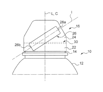
Figure 1 is a schematic view of a closure mounted on the neck of a liquid
container
(partly represented) according to an embodiment of the invention, when the
closure is in a
closed position;
Figure 2 is a schematic perspective view of the Figure 1 closure in an open
position;
Figure 3 is a schematic view analogue to Figure 1 but with a different
orientation of
the hinge member;
Figure 4 is a cross-section view of the cap and base portion of Figure 1
closure;
Figure 5 is a schematic view of the mould interface used for moulding Figure 4
closure on section plane AA;
Figure 6 is a cross-section view of Figure 5 mould on section plane ZZ;
Figure 7 schematically represents the mould interface local shape used for
moulding
the hinge member of Figure 4 closure;
Figures Ba-c schematically depict steps of a method according to the
invention.
Detailed description of the invention
Figures 1 and 2 represent partial views of a liquid container 10 (e.g. a
bottle of water)
in a vertical position.
Liquid container 10 comprises a body 12 that is partly represented in Figures
1 and
2 and a neck 14.
Neck 14 has an aperture through which the liquid contained within body 12 may
be
dispensed.
A one-piece closure 16 is mounted on the neck for closing the aperture.
The aperture is not represented in Figure 1 where closure 16 is in a closed
position.
6
CA 2839799 2019-05-23
Closure 16 is in an open position in Figure 2. An additional plastic plug 18
(e.g. a
sports cap) having a central upper hole 20 is located in the neck aperture so
as to reduce
the passage for dispensing liquid out of the container and facilitate
dispensing for a consumer.
Closure 16 closes the restricted liquid passage 20 of Figure 2 when in closed
position.
Closure 16 comprises a base portion 22 that inwardly defines an opening
centered
about a base portion longitudinal axis L.
As represented in Figures 1 and 2, this portion 22 arranged around neck 14 is
permanently secured thereto through conventional means, e.g. by undercut,
snapping,
interbeads, etc.
Closure 16 further comprises a cap 24 that is linked to the base portion 22 by
an
outside hinge member 26, also commonly referred to as "hinge" in the remainder
of the
description.
Hinge member or hinge 26 is made integrally with cap 24 and base portion 22
and,
for example, is flexible. Hinge 26 is a flexible piece which enables cap 24 to
move relative to
fixed base portion 22.
Before first use of the liquid container the cap 24 is secured to the base
portion 22 by
connecting bridges, more generally by tamperproof means, which are obtained in
a known
manner when moulding the closure.
Before using the container for the first time a consumer/user has to deform
and break
these tamperproof means so as to enable separation of the cap and the base
portion from
each other with a view to opening the liquid container.
Hinge 26 is inclined with respect to the base portion longitudinal axis L when
the cap
is in the Figure 1 closed position.
As represented in Figures 1 and 2, the hinge of the closure is oriented
clockwise with
respect to longitudinal axis L which represents, here, a vertical line. In an
alternate
embodiment depicted in Figure 3, the closure 40 has an inclined hinge 42 that
is oriented
counter-clockwise.
The other features of hinge 42 are the same as those of Figures 1 and 2.
Reverting to Figure 1, hinge 26 has two opposite ends 26a and 26b which
together
define the length of the hinge.
Hinge 26 has a rather elongated shape.
The two opposite ends 26a and 26b are respectively connected to cap 24 and
base
portion 22 and are integral therewith.
7
CA 2839799 2019-05-23
As represented in Figure 1, opposite ends 26a and 26b are aligned along an
axis I
that is inclined with respect to the base portion longitudinal axis L when the
cap is in the
closed position.
Axis I defines the overall inclination of hinge 26.
In Figures 1 and 2 axis I is inclined at an angle of approximately 45 with
respect to
longitudinal axis L.
An angle of inclination around 45 , that is in a range lying from 45 -
several degrees
to 45 + several degrees provides satisfactory results in terms of easiness of
demoulding and
clearance when the cap is in the open position (Figure 2)
However, the invention is not limited to these values as will be explained
later on.
Hinge 26 is generally flat and, for instance, has the overall shape of a
strip.
Such a strip has a rectangular cross-section.
It is to be noted that the length of hinge 26 is greater than the length of a
vertically-
extending hinge as known in the prior art.
This greater length makes the hinge more flexible than the prior art shorter
vertical
hinges.
This contributes to obtaining a better clearance position when the cap is in
the Figure
2 open position.
Furthermore, the greater length of the inclined hinge makes it more robust
from a
mechanical point of view.
This robustness is a feature which is useful when opening the cap from Figure
1 to
Figure 2 position where the hinge is subjected to torsion.
Thanks to the inclination of the hinge the hinged cap is arranged in an open
position
(Figure 2) providing much less interference with the face of a consumer
wanting to drink
directly from the container.
In the open position the cap is arranged on a side of the container at a
greater
distance from the base portion and neck than in the prior art.
It is to be noted that in the Figure 1 closed position cap 24 is centered
about a cap
axis C that coincides with the base portion longitudinal axis L, whereas in
the Figure 2 open
position cap axis C does not intersect with axis L.
This arrangement is contrary to the prior art arrangement where the axis of
the cap
connected to its base portion by a vertical hinge still intersects the base
portion longitudinal
axis in the open position.
8
CA 2839799 2019-05-23
Put it another way, in the open position the interior of the cap is rather
laterally
oriented since it rotated about an axis that is not perpendicular to a
vertical plane containing
axis L (in the prior art, the cap rotates about an axis that is perpendicular
to a vertical plane
containing axis L).
Figure 4 depicts a schematic cross-section view of closure 16.
More particularly, only cap 24 and base portion 22 are represented in cross-
section,
whereas the hinge 26 is represented in a perspective view.
A cross-section plane AA intersects hinge 26 at a distance from cap 24.
Closure 16 is formed by injection moulding in a mould which comprises two
parts.
Figure 5 schematically depicts the two mould parts 50 and 52 in a closed
position in which
they define together a mould jointing plane interface 54.
Figure 5 is a cross-section view on the inclined section plane AA of Figure 4.
Closure 16 is in the background and is represented in dotted lines.
Figure 6 is a cross-section view on the section plane ZZ of Figure 5.
As represented in Figure 6, closure 16 has already been formed by an injection
moulding process that will be described subsequently.
Each mould part 50, 52 respectively defines an internal cavity 56, 58, both
internal
cavities facing each other along a longitudinal axis of alignment denoted M.
The longitudinal axis of alignment M of the mould coincides with base portion
longitudinal axis L.
The internal base portion 22 and cap 24 are moulded inside internal cavities
58 and
56 respectively in cooperation with a removable insert or core member 60 that
has been
introduced into said cavities.
Only a portion of hinge 26 is represented in Figure 6 cross-section.
As represented in Figure 5, mould jointing plane 54 is locally shaped so as to
enable
moulding of the inclined hinge 26.
Mould jointing plane 54 has a local portion that is located in the area
between the
closure (cap and base portion) and the hinge 26 and which is represented on a
side view in
Figure 5. This local portion extends from a first segment that is adjacent to
the highest point
of hinge 26 and represented by point H in Figure 5 to a second segment that is
adjacent to
the lowest point of hinge 26 and represented by point B.
On a 3D view this local portion assumes the shape of an helicoIdal surface.
9
CA 2839799 2019-05-23
More particularly, mould jointing plane 54 includes a local interface portion
that has a
substantially Z shape or inverted Z shape for moulding inclined hinge 26.
Moulding hinge 26 having a clockwise orientation requires a substantially
inverted Z-
shaped interface portion.
Alternatively, a mould interface portion used for moulding the inclined hinge
42 in
Figure 3 (anti-clockwise orientation) is substantially Z-shaped.
The locally-shaped interface portion 62 is inclined with respect to the
longitudinal axis
of alignment M of the two mould parts.
More particularly, the substantially inverted Z-shaped interface portion 62
has two
legs 62a and 62b and a middle portion 62c extending inclined between these two
legs.
As represented in Figure 5, the locally-shaped interface portion 62
interconnects two
distant portions 64a and 64b of mould jointing plane 54 that are respectively
located at
different heights along axis M.
Figure 7 schematically illustrates mould jointing plane 54 without the mould
parts and
closure.
The locally-shaped interface portion 62 is connected to an upper portion 54b
of mould
jointing plane 54 through upper leg 62a, whereas it is connected to lower
portion 54a of mould
jointing plane 54 through lower leg 62b.
As represented in Figure 7, upper leg 62a has an upper end H and a lower end
H',
whereas lower leg 62b has an upper end B' and a lower end B.
As the locally-shaped interface portion 62 is inclined with respect to
longitudinal axis
M, upper leg 62a is located at a higher position than lower leg 62b. This
therefore means that
lower end H' of upper leg 62a is higher than upper end B' of lower leg 62b.
Thus, it is to be understood that the inclination of the locally-shaped
interface portion
with respect to axis M has an upper limit (in terms of angle) that is defined
by the position of
the lower end H' of upper leg 62a above the position of the upper end B' of
lower leg 62b.
Conversely, this locally-shaped interface portion may be much less inclined
with
respect to axis M and the lower limit of this inclination is defined by
respective points HL and
BL (Figure 7).
These points represent the respective positions that upper end H of upper leg
62a
and lowest end B of lower leg 62b may occupy while still permitting easy
demoulding of the
inclined hinge.
CA 2839799 2019-05-23
The positions represented by points HL and BL are very close to axis M so that
in this
extreme position middle portion 62c may be inclined at a small angle of
several degrees with
respect to axis M.
For example, the small angle (extreme angle) may be of 50 approximately.
These furthest positions can be easily obtained through simple experiments and
trials.
A method of forming by injection moulding a liquid container closure, as
closure 16,
will now be described with reference to Figures 8a-c.
This method comprises several steps.
According to a first step, the two parts 50 and 52 of the mould are provided.
As has been already mentioned above, these two mould parts respectively define
internal cavities which are generally centrally-located within the mould
parts.
According to a second step, the two mould parts are assembled together by
being
moved along longitudinal axis M as illustrated in Figure 8a.
It is to be noted that only one of the two mould parts may alternatively be in
a fixed
position while the other mould part is movable.
As represented in Figure 8b, the two mould parts have been assembled together
with their two internal cavities facing each other as also illustrated in
Figures 5 and 6.
It is also to be noted that when assembled together the two mould parts define
therebetween a local recess that radially extends outwardly from said central
internal cavities
56 and 58.
This local recess has a complex 30 shape which cannot be easily represented in
a
perspective view. It is used for moulding the hinge member of the closure.
This recess can be seen only in part in the Figures 5 and 6 cross-sections
where
hinge 26 is apparent.
In a further step still illustrated in Figure 8b, a removable insert or core
member 60
is introduced into the two mould parts internal cavities in order to occupy a
position that is
represented in Figure 6.
In this position a space is defined between insert 60 and the inner walls of
cavities 56
and 58.
This space is in communication with the local recess defined above and which
is
intended for moulding hinge 26.
In a next step, a liquid material such as a thermoplastic resin is injected
through
injection channels (not represented in the drawings) which communicate with
internal cavities
11
CA 2839799 2019-05-23
56 and 58. The above-defined space and local recess are thus filled by the
injected liquid
material.
The injection process is performed in a conventional manner, in particular
under
known temperature and pressure conditions which will not be detailed here.
Once one-piece closure 16 has been thus formed by injection moulding, insert
60 is
withdrawn in a direction opposite to that represented in Figure 8b with a view
to demoulding
the one-piece moulding.
As represented in Figure 8c, the two mould parts 50 and 52 are spaced part
from
each other for opening the mould and demoulding the closure and, in
particular, hinge 26.
This demoulding step is quite easy to carry out since the two mould parts have
only
to be moved along the longitudinal axis of alignment M of the mould in the
opposite direction
to that one depicted in Figure 8a.
This easy demoulding is made possible by virtue of the inclined hinge.
Contrary to prior art methods, there is no additional insert or drawer to be
removed
before separating the two mould parts from each other for demoulding the
hinge.
This is because in the prior art the mould jointing plane used for moulding
the vertical
hinge is parallel to the axis of alignment of the mould parts, namely
vertical, whereas in the
present invention the mould jointing plane is inclined with respect to axis M.
Thanks to the inclined hinge the moulding and demoulding process is made
easier
and cheaper.
Furthermore, the injection mould is therefore made easier and more robust than
in
the past.
In addition, demoulding the closure by simply separating two mould parts along
longitudinal axis M (vertical axis) makes it possible to increase the number
of closures
manufactured at a time.
The yield of the manufacturing process is therefore increased.
It should be understood that various changes and modifications to the
presently
preferred embodiments described herein will be apparent to those skilled in
the art. Such
changes and modifications can be made without departing from the spirit and
scope of the
present invention and without diminishing its attendant advantages. It is
therefore intended
that such changes and modifications be covered by the appended claims.
12
CA 2839799 2019-05-23