Note: Descriptions are shown in the official language in which they were submitted.
WO 2012/177690 PCT/US2012/043239
METHOD AND APPARATUS FOR IMPLEMENTING SIGNAL QUALITY METRICS
AND ANTENNA DIVERSITY SWITCHING CONTROL
FIELD OF THE INVENTION
[0001] This invention relates to digital radio broadcasting receivers,
and more
particularly to methods and apparatus for implementing signal quality metrics
and switching
control logic for antenna diversity switching in a radio receiver.
BACKGROUND OF THE INVENTION
[0002] Digital radio broadcasting technology delivers digital audio and
data services
to mobile, portable, and fixed receivers. One type of digital radio
broadcasting, referred to as
in-band on-channel (IBOC) digital audio broadcasting (DAB), uses terrestrial
transmitters in
the existing Medium Frequency (MF) and Very High Frequency (VHF) radio bands.
HD
RadioTM Technology, developed by iBiquity Digital Corporation, is one example
of an IBOC
implementation for digital radio broadcasting and reception.
100031 IBOC DAB signals can be transmitted in a hybrid format including
an analog
modulated carrier in combination with a plurality of digitally modulated
carriers or in an all-
digital format wherein the analog modulated carrier is not used. Using the
hybrid mode,
broadcasters may continue to transmit analog AM and FM simultaneously with
higher-quality
and more robust digital signals, allowing themselves and their listeners to
convert from
analog to digital radio while maintaining their current frequency allocations.
[0004] IBOC DAB technology can provide digital quality audio, superior
to existing
analog broadcasting formats. Because each IBOC DAB signal is transmitted
within the
spectral mask of an existing AM or FM channel allocation, it requires no new
spectral
allocations. IBOC DAB promotes economy of spectrum while enabling broadcasters
to
supply digital quality audio to the present base of listeners.
[00051 The National Radio Systems Committee, a standard-setting
organization
sponsored by the National Association of Broadcasters and the Consumer
Electronics
Association, adopted an IBOC standard, designated NRSC-5, in September 2005.
NRSC-5
sets forth the requirements for
broadcasting digital audio and ancillary data over AM and FM broadcast
channels. The
standard and its reference documents contain detailed explanations of the
RF/transmission
subsystem and the transport and service multiplex subsystems. iBiquity's HD
Radio
Technology is an implementation of the NRSC-5 IBOC standard.
- 1 -
CA 2 8 3 98 7 9 2 0 1 8-0 8-2 1
CA 02839879 2013-12-18
WO 2012/177690 PCMJS2012/043239
[0006] Other types of digital radio broadcasting systems include satellite
systems such
as XM Radio, Sirius and WorldSpace, and terrestrial systems such as Digital
Radio Mondiale
(DRM), DRM+, Eureka 147 (branded as DAB), DAB Version 2, and FMeXtra. As used
herein, the phrase "digital radio broadcasting" encompasses digital audio
broadcasting
including in-band on-channel broadcasting, as well as other digital
terrestrial broadcasting
and satellite broadcasting.
[0007] Antenna diversity techniques are used to mitigate the effects of
distortion and
outages due to multipath propagation of the received FM signal. Diversity can
also
accommodate the directional characteristics of glass-embedded window antennas.
A variety of
diversity antenna techniques have been developed and deployed for use with
automotive FM
receivers. Although all FM receivers, including tabletop, home theater, and
portable receivers,
could benefit from antenna diversity, only automotive receivers presently
employ diversity
techniques. Furthermore, the diversity algorithms developed for analog FM
receivers are
generally not appropriate for HD Radio digital reception.
[0008] It would be desirable to have a metric for the quality of a
received radio signal
that can be used to control antenna diversity switching, as well as switching
control logic
appropriate for the IBOC signals.
SUMMARY
[0009] In a first aspect, the invention provides a method for detecting
the quality of a
radio signal, including: receiving a radio signal including a digital portion
modulated by a series
of symbols each including a plurality of samples; computing correlation points
between
endpoint samples in cyclic prefix regions of adjacent symbols; and using the
correlation points
to produce a digital signal quality metric.
[00010] In another aspect, the invention provides an apparatus including: a
radio receiver
including an input for receiving a radio signal having a digital portion
modulated by a series of
symbols each including a plurality of samples, and a processor for computing
correlation points
between samples in cyclic prefix regions of adjacent symbols to produce a
digital signal quality
metric.
[00011] In another aspect, the invention provides a method including:
receiving a radio
signal including an analog-modulated portion; digitally sampling an analog-
modulated portion
of the radio signal to produce a plurality of samples; and using a ratio
between an average
- 2 -
CA 02839879 2013-12-18
WO 2012/177690 PCMJS2012/043239
magnitude and an RMS magnitude of a block of the samples to compute an analog
signal
quality metric.
[00012] In another aspect, the invention provides an apparatus including: a
radio receiver
including an input for receiving a radio signal having an analog-modulated
portion; and a
processor for digitally sampling the analog-modulated portion to produce a
plurality of samples;
and using a ratio between an average magnitude and an RMS magnitude of a block
of the
samples to compute an analog signal quality metric.
[00013] In another aspect, the invention provides a method including: (a)
receiving a
radio signal on a plurality of antenna elements; (b) computing a signal
quality metric for the
signal received on each of the antenna elements; (c) determining a difference
value between the
signal quality metric for the currently selected antenna element and the
signal quality metric for
each of the other antenna elements; (d) finding the minimum difference value;
(e) determining
(1) if a dwell value for the currently selected antenna element is greater
than a multiple of the
minimum difference value and (2) if the signal quality metric for the
currently selected antenna
element is less than a threshold value; and (f) if either or both of (1) or
(2) in step (e) is true,
then switching from the currently selected element to one of the other antenna
elements for
supplying the radio signal to a receiver, and repeating steps (b) through (e).
[00014] In another aspect, the invention provides an apparatus including: a
plurality of
antenna elements for receiving a radio signal; a switch for connecting one or
more of the
antenna elements to an input of a receiver; and a processor for (a) computing
a signal quality
metric for the signal received on each of the antenna elements, (b)
determining a difference
value between the signal quality metric for the currently selected antenna
element and the signal
quality metric for each of the other antenna elements, (c) finding the minimum
difference value,
(d) determining (1) if a dwell value is greater than a multiple of the minimum
difference value
and (2) if the signal quality metric for first antenna element is less than a
threshold value, and (e)
if either or both of (1) or (2) in step (e) is true, then controlling the
switch to switch from the
currently selected element to one of the other antenna elements for supplying
the radio signal to
the receiver and repeating steps (a) through (d).
[00015] In another aspect, the invention provides a method including:
receiving a radio
signal on a plurality of antenna elements; computing a signal quality metric
for the signal
received on each of the antenna elements; using the signal quality metric for
an antenna element
currently supplying the radio signal to a receiver to determine if diversity
switching is desired;
- 3 -
CA 02839879 2013-12-18
WO 2012/177690 PCMJS2012/043239
and producing a proxy control signal that causes a diversity switch control to
implement a
desired switching of the antenna elements.
[00016] In another aspect, the invention provides a method including:
receiving a radio
signal on a plurality of antenna elements, wherein the radio signal includes
an analog modulated
portion and a digitally modulated portion; computing an analog signal quality
metric for the
analog modulated portion of the received radio signal; computing a digital
signal quality metric
for the digital modulated portion of the received radio signal; and using
either the analog signal
quality metric or the digital signal quality metric to select one or more of
the antenna elements
to be connected to a receiver input, wherein a reaction time for selecting the
antenna elements
based on the analog signal quality metric is shorter than a reaction time for
selecting the antenna
elements based on the digital signal quality metric.
[00017] In another aspect, the invention provides an apparatus including: a
plurality of
antenna elements for receiving a radio signal, wherein the radio signal
includes an analog
modulated portion and a digitally modulated portion; a switch for connecting
one or more of the
antenna elements to an input of a receiver; and a processor for computing an
analog signal
quality metric for the analog modulated portion of the received radio signal,
computing a digital
signal quality metric for the digital modulated portion of the received radio
signal, and using
either the analog signal quality metric or the digital signal quality metric
to produce a switch
control signal for selecting one or more of the antenna elements to be
connected to a receiver
input; wherein a reaction time for selecting the antenna elements based on the
analog signal
quality metric is shorter than a reaction time for selecting the antenna
elements based on the
digital signal quality metric.
BRIEF DESCRIPTION OF THE DRAWINGS
[00018] FIG. 1 is a block diagram of an FM receiver for use in an in-band on-
channel
digital radio broadcasting system.
[00019] FIG. 2 is a block diagram of isolation filters that can be used in the
receiver of
FIG. 1.
[00020] FIG. 3 is a graph of quality values for upper and lower digital
sidebands over
several measurement samples.
[00021] FIG. 4 is a graph of analog signal quality metric as a function of
carrier-to-noise
ratio.
- 4 -
WO 2012/177690 PCT/US2012/043239
[00022] FIG. 5 is a functional block diagram of a receiver that includes
antenna diversity
using analog and digital signal quality metrics.
[00023] FIG. 6 is a simplified block diagram of an example automotive FM
receiver with
switched diversity.
[00024] FIG. 7 is a simplified block diagram of an alternate FM IBOC
automotive
receiver with switched diversity.
[00025] FIG. 8 is a simplified block diagram of an alternate FM receiver with
switched
diversity using a proxy diversity control signal.
DETAILED DESCRIPTION
[00026] In one aspect, this invention relates to methods and apparatus for
implementing
signal quality metrics that can be used to implement antenna diversity
switching in HD Radio
receivers. Descriptions of an HD Radio broadcasting system are provided in
United States
Patent No. 7,933,368, for a "Method and Apparatus for Implementing a Digital
Signal Quality
Metric" and United States Patent Application Publication No. 2009/0079656.
[00027] As shown in United States Patent Application Publication No.
2009/0079656, a
hybrid FM IBOC waveform includes an analog modulated signal located in the
center of a
broadcast channel, a first plurality of evenly spaced orthogonally frequency
division multiplexed
subcarriers in an upper sideband, and a second plurality of evenly spaced
orthogonally
frequency division multiplexed subcarriers in a lower sideband. The digitally
modulated
subcarriers are divided into partitions and various subcarriers are designated
as reference
subcarriers. In one implementation, a frequency partition is a group of 19
OFDM subcarriers
containing 18 data subcarriers and one reference subcarrier.
[00028] The hybrid waveform shown in United States Patent Application
Publication
No. 2009/0079656 includes an analog FM-modulated signal, plus digitally
modulated
subcarriers. The subcarricrs are located at evenly spaced frequency locations.
The amplitude of
each subcarrier can be scaled by an amplitude scale factor.
DIVERSITY WITH HD RADIO SIGNALS
[00029] HD Radio signals always carry a digital component, and an analog host
signal is
also present in the more-common hybrid signals. The digital signal component
is more tolerant
of fading than its analog counterpart, due to digital properties of
interleaving, forward error
correction (FEC) coding and frequency/time diversity. Selective fading can be
tracked with
- 5 -
CA 2839879 2018-08-21
WO 2012/177690 PCT/US2012/043239
channel state information (CSI) estimates over time and frequency for the
digital signal. The
CSI is used to derive weights for the symbol information as a function of its
estimated
reliability. However, antenna diversity is still needed to accommodate
directional antenna
patterns or long, flat-fading outages lasting a substantial portion of the
interlcaver span. Since
the digital signal is coherently detected and tracked, each antenna switching
event is likely to
cause symbol corruption and temporary loss in CSI and coherent tracking.
Modifications to the
digital modem have been previously designed to somewhat mitigate the effects
of the switching,
although switching losses are still significant. Therefore antenna diversity
switching for digital
signals can be a slower process than for analog signals. Specifically, for the
digital signal
component, antenna switching is needed to avoid long, broadband outages due to
slow fading
(including fixed conditions) as well as antenna directionality losses.
[00030] A different antenna switching strategy would be more appropriate for
the FM
analog signal component. The difference in diversity switching strategy
between analog and
digital components of an HD Radio hybrid FM signal can be summarized as
follows. For FM
analog signals, the switching reaction time is generally small (tens of
microseconds) to avoid
signal corruption in a fade, or frequency-selective null. For digital signals,
the desired switching
reaction time can be tens of milliseconds, or greater, to avoid long,
broadband outages due to
slow fading (including fixed conditions) as well as antenna directionality
losses. Therefore, it
would be desirable to use different switching criteria to handle diversity
switching with a hybrid
signal, depending on whether the audio output is derived from the digital or
analog signal.
Importantly, the FM analog diversity switching algorithm will not work when
the IBOC signal
is all digital (not hybrid). The switching action would be excessive if the
analog signal were
missing.
[00031] One embodiment of the present invention includes some of the elements
of a
receiver described in United States Patent No. 7,933,368, for a "Method and
Apparatus for
Implementing a Digital Signal Quality Metric".
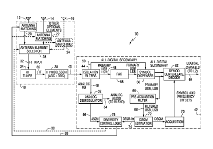
[00032] FIG. 1 is a functional block diagram of an FM receiver 10 having
multiple
antenna elements 12, 14, and 16 and employing antenna element diversity, as
well as adaptive
impedance matching (AIM) functions. AIM is described in United States Patent
Application
Publication No. 2010/014495. In one embodiment, an antenna element 12 can be
an antenna
incorporated into an earbud wire; antenna element 14 can be a loop antenna;
and element 16
represents one or more additional, optional antennas. Within an RF/IF
processor 18, a first
- 6 -
CA 2 8 3 98 7 9 2 0 1 8-0 8-2 1
CA 02839879 2013-12-18
WO 2012/177690 PCMJS2012/043239
antenna matching circuit 20 dynamically matches the impedance of antenna
element 12 to the
receiver, a second antenna matching circuit 22 dynamically matches the
impedance of antenna
element 14 to the receiver, and optional additional antenna matching circuits
24 can be used to
dynamically match the impedance of any additional antenna elements to the
receiver. While the
antenna matching functionality is shown in FIG. 1 as part of the RF/IF
processor, this
functionality may be implemented in other discrete components of a receiver
device such as an
RF front end. Antenna element selector 28 selects a signal from one of the
antenna elements
based on an antenna element diversity control signal 30, and passes that
signal as an RF input 32
to RF tuner 34. Alternatively, the antenna element selector can pass on the
sum or difference of
the signals received on the various antenna elements. The RF tuner produces an
IF signal 36,
which is converted from analog to digital and digitally down converted by IF
processor 38 to
produce a baseband signal 40 at a rate of 744,187.5 complex samples per
second.
[00033] The baseband signal is received by baseband processor 42, which
applies
isolation filters 44 to produce a digitally sampled, analog signal 46 at a
rate of 186,046.875
complex samples per second, primary upper sideband and lower sideband digital
signals 48 at a
rate of 186,046.875 complex samples per second, and an all-digital secondary
signal 50 at a rate
of 372,093.75 complex samples per second. Analog demodulator 52 receives the
digitally
sampled analog signal 46 and produces an analog audio output 54 and an analog
signal quality
metric (ASQM) 56. The operation of analog demodulator 52 and calculation of
the ASQM is
described in more detail below. A first-adjacent cancellation operation 58 is
applied to the
primary upper and lower sidebands in order to minimize any interference from a
first-adjacent
signal. Symbol dispenser 60 aligns and dispenses the incoming data stream into
segments
representing one OFDM symbol. The all-digital secondary signal and primary
upper and lower
sidebands are then demodulated, deinterleaved, and decoded (62), and then
passed as logical
channels 64 to Layer 2 of the receiver protocol stack for demultiplexing, as
described in US
Patent Application Publication No. 2009/0079656. A pre-acquisition filtering
process 66 is
applied to the primary upper and lower sidebands to produce filtered upper and
lower sideband
signals 68 at a rate of 46,511.71875 complex samples per second. Acquisition
processing 70
produces symbol timing and frequency offsets. DSQM estimation 72 calculates a
digital signal
quality metric (using for example, the DSQM algorithm disclosed in US Patent
No. 7,933,368,
or the DSQM-lite algorithm disclosed below). DSQM-lite is output on line 74,
which is used by
the diversity control logic 76 after acquisition has been established. Pre-
acquisition filtering and
- 7 -
CA 02839879 2013-12-18
WO 2012/177690 PCMJS2012/043239
DSQM estimation are shown and described in more detail below. Diversity
control logic 76
receives the analog signal quality metric (ASQM) and digital signal quality
metric (DSQM-lite),
and produces antenna element diversity control signal 30. Diversity control
logic 76 preferably
receives the ASQM and DSQM-lite signals at an update rate of roughly 20 Hz or
possibly lower
for home or portable devices.
[00034] When the receiver is used in a hybrid IBOC system, both an analog
signal
quality metric (ASQM) and a digital signal quality metric (DSQM-lite) are
needed for antenna
diversity switching. Algorithms for efficient ASQM and DSQM-lite computation
are described
herein.
[00035] To construct the DSQM-lite algorithm, the computational complexity of
the
DSQM algorithm (of US Patent No. 7,933,368) has been reduced by taking
advantage of
symbol synchronization after the signal has been acquired, establishing
frequency tracking and
symbol synchronization. The DSQM algorithm of US Patent No. 7,933,368 computes
correlation points for all the samples of each symbol, although only the
correlation samples in
the cyclic-prefix regions are useful. This is done because the locations of
the cyclic-prefix
samples within each symbol are not known prior to acquisition. However, since
the locations of
the cyclic-prefix regions of the symbols are known following acquisition,
there is no need to
compute correlation points across the entire symbol. As used in this
description, symbol
acquisition means locating and synchronizing to the symbol boundaries. This
allows a
simplified DSQM algorithm that computes only the filtered correlation-peak
samples in the
symbol-synchronized cyclic-prefix region. This simplified algorithm is labeled
DSQM-lite.
Since DSQM-lite is based on DSQM, the reader is referred to the DSQM Patent
No. 7,933,368,
and only the details of computing DSQM-lite are shown here.
[00036] In one example, both the DSQM and DSQM-lite algorithms process groups
of
16 symbols to produce a digital signal quality metric. While 16 symbols have
been determined
to be sufficient to reliably enhance and locate the correlation peak, the
invention is not limited to
any particular number of symbols. The processing described below includes two
operations:
pre-acquisition filtering and acquisition processing. First,
an efficient isolation filter
architecture is presented, including pre-acquisition filtering.
[00037] The efficient implementation of isolation filters, and decimation to
minimum
sample rates, can reduce subsequent MIPS requirements, and save power.
Recognition of some
complementary characteristics of these filters is important in realizing the
efficient filter design.
- 8 -
CA 02839879 2013-12-18
WO 2012/177690 PCMJS2012/043239
The combination of input sample rate, bandwidths, and locations of the analog
FM signal and
digital sidebands, along with the decimate-by-4 frequencies, offers a
convenient filter
architecture.
[00038] To prevent DSQM degradation due to large second-adjacent channels,
each
primary sideband is filtered prior to acquisition processing. To reduce the
MIPS requirement,
this filter can be implemented as a decimate-by-16 filter (from the original
sample rate of
744,187.5 Hz), with an output sample rate of 46,511.71875 Hz. In one
implementation shown
in FIG. 2, each digital sideband is first decimated by 4 to 186,046.875 Hz for
normal OFDM
demodulation of each sideband. Although not shown in FIG. 2, FAC (First
Adjacent
Canceling, an interference mitigation algorithm) processing may be performed
on each
sideband.
[00039] FIG. 2 is a functional block diagram of the isolation filters 44. The
input signal
40 from the front end circuit is input to a halfquarter finite impulse
response (FIR) filter 80.
This "halfquarter" filter establishes the locations of all the transition
bands. This set of
characteristics allows for exploitation of an input filter having both
halfband and quarterband
symmetries, resulting in zero coefficients except for every fourth sample.
This is followed by an
efficient halfband Hilbert transform filter 86 to separate the upper and lower
digital sidebands,
and another similar halfband filter 84 to separate and reduce the sample rate
of the analog FM
signal and to isolate the secondary digital sidebands of an all digital
signal. In FIG. 2, all signals
are complex, and all filters are real, except the Hilbert FIR filter 86.
Halfband and quarterband
symmetry is common language of filter designers. These symmetries result in
some efficiency
advantages, and can be exploited here in some unique ways (e.g., adding and
subtracting instead
of refiltering some frequency bands in the isolation filters).
[00040] FIG. 2 shows that the isolation filters can decimate the center
baseband sample
rate of S=744,187.5 by a factor of either 3 or 4. This center isolation filter
is used for isolating
the analog FM signal. The 6-dB filter bandwidth, however, is 93 kHz in
either case. The less-
aggressive decimation by 3 can prevent some small frequency components just
above 93 kHz
from aliasing back into the output. However, simulation results indicate that
this benefit is not
significant in Total Harmonic Distortion plus Noise (THDN) performance, even
in 120%
overmodulation conditions. Another potential benefit of the decimate-by-3
option is that there
is less distortion in FM detection due to the difference (instead of the
derivative) approximation
of the digitally-sampled detection. However, the distortion compensation
demonstrated
- 9 -
CA 02839879 2013-12-18
WO 2012/177690 PCMJS2012/043239
(simulated) for the FM detector virtually eliminates this loss. Therefore the
decimate-by-4
option to 186 kHz seems preferred in the interest of MIPS reduction.
1000411 The digital sidebands are then translated in frequency by xp( j = 7*
it / 3) for
the upper sideband (USB) or lower sideband (LSB), respectively. The net
frequency translation
is 155,039.0625 Hz from the original sideband frequency due to sample-rate
aliasing
(186,046.875-Hz shift to dc) and the exponential frequency shift (31,007.8125
Hz). This places
the subcarriers previously-centered at 155,039.0625 Hz at zero Hz for
subsequent lowpass
filtering on each upper and lower sideband, respectively. The frequency-
shifted upper sideband
signal xvper and lower sideband signal x/õõ are:
xvpõ[n] = USB[n] exp n 7/3
X lo wer[n] = LSB[n]= exp ¨ j = n = 7T /3 1
for thenth sample in a semi- infinite stream.
a
[00042] Then the cascaded pre-acquisition filter decimates by another factor
of 4 with
23-tap FIR filter. The integer taps defined by hqb represent a quarter-band
filter, and can be
scaled by 245 to yield a unity-gain passband. The expression hqb represents
the filter impulse
response (filter taps) for a FIR filter with quarterband symmetry. In one
example:
hqb=(40,100,130,0,-386,-852,-912,0,2080,4846,7242,8192,7242,4846,2080,0,-912,-
852,-
386,0,130,100,40)T.
[00043] For example, the decimated filter output samples for each sideband are
computed as:
y[in]= x k + in¨ .11- hqb[k]
k=
for the mth s ample in a semi- infinite stream
where y[m] is the decimated filter output, x is the decimation-filter input,
and hqb is the filter
impulse response (filter taps) for a FIR filter with quarterband symmetry.
[00044] The DSQM-lite processing starts with these sideband signals. Due to a
cyclic
prefix applied at the transmitter, the first and last 6 samples (at the
preacquisition sample rate
of 46.5 kcsps) of each transmitted symbol are highly correlated. DSQM-lite
processing
reveals this correlation by complex-conjugate multiplying each sample in an
arbitrary (or
-10-
CA 02839879 2013-12-18
WO 2012/177690 PCMJS2012/043239
first) symbol with a sample in a preceding (or second) symbol 128 samples
away. When the
products of these multiplications are synchronized to a symbol's cyclic-prefix
region, they
form a 6-sample peak with a common phase, and an amplitude that reflects a
root-raised-
cosine pulse shape. To reduce the noise in the peak, the corresponding
products of samples in
the cyclic prefix regions of 16 contiguous symbols are "folded" on top of one
another (i.e.,
pointwise added) to form a 6-sample result.
[00045] Since the symbol boundaries are already established in the symbol
dispenser
(symbol synchronizer) when the DSQM-lite is used for diversity switching,
there is no need
to compute more than one peak, and the phase information is not used for
diversity switching.
Only the DSQM-lite magnitude between zero and one is used.
[00046] The following algorithm provides a computationally efficient means of
calculating a digital signal quality metric for antenna diversity switching.
It includes aspects
of the acquisition version of DSQM described in US Patent No. 7,933,368,
however the
complexity is reduced because the location of symbol boundaries is known once
acquisition is
complete. Therefore, computations need only occur on samples comprising the
correlation
peak. The process includes pre-acquisition filtering and DSQM-lite
calculation. This
function is called only after acquisition is successful.
[00047] After initial acquisition, a substantial reduction in MIPS can be
realized by
limiting the processing of signal samples to the cyclic-prefix regions of the
symbols. Since
the symbol samples are already framed by the symbol dispenser in the receiver
of FIG. 1, it is
relatively straightforward to select the cyclic-prefix regions for DSQM-lite
processing. In one
embodiment, 6 samples are processed at each end of the 135-sample symbol at
the decimate-
by-16 sample rate. In the example described below, only sample indices 1
through 6 and 129
through 134 are computed; sample 0 is not needed since it should be
synchronized to have a
zero value.
[00048] The center of pre-acquisition decimation filter hell) for a 540-sample
input
symbol will be aligned at input sample indices 4, 8, 12, 16, 20, and 24, as
well as at
corresponding locations 512 samples later (i.e., at indices 516, 520, 524,
528, 532, and 536).
After initial acquisition, the indexed input samples outside the present
symbol boundary can
be assigned a zero value. Further simplification can be realized by re-
indexing the output
samples. Re-indexing is simply renumbering the signal samples (for
convenience).
-11-
CA 02839879 2013-12-18
WO 2012/177690 PCMJS2012/043239
[00049] Vectors for complex frequency shifting and filter coefficients are
computed
and pre-stored. One example pre-stored complex exponential is a 6-element
vector fshft . The
upper USB and lower LSB sideband signals are cyclically (modulo-6 elements)
multiplied by
the vector fshft to shift the center of the target OFDM subcarriers to zero
Hz, as described
above.
1 1
exp = /3 1 0.5+j0.866
exp A= 2.7 / 3 ¨ 0.5 +j=0.866
fshft= _ =
¨1 1 ¨1
exp ¨ j =2=7z-13 ¨0.5¨ j= 0.866
exp ¨ j = It /3 1) 0.5¨ j = 0.866 )
[00050] The correlation samples are weighted with a 6-tap FIR filter whose
impulse
response is matched to the shape of the peak. FIR filters h and h2 are matched
to the shapes
of the peaks to be computed for 6-element vectors u and v, respectively.
h[m] = co 71. (2 5) = and h2[in] = h2[m]
form = 0,1,...,5
14 ) 2
(0.434) (0.094)
0.782 0.306
0.975 I 0.475
h= ; and h2=
0.975 I 0.475
0.782 0.306
0.434) 0.094)
[00051] The DSQM-lite computation includes 6 steps.
[00052] STEP 1: Place the frequency-shifted symbol endpoints pshfi and gshft
for the
upper and lower sidebands in vectors for each symbol:
rUSB[n ¨ ]= fshff mod(n + ,6)] ; for n >
pshftupper[n] =
L 0; otherwise
r USB[n + 05] = fshffmod(n + ,6)] ; for n < 5
qshfpõ[n]=
); otherwise
LSB[n ¨ ]= fshfi[mod(n + ,6)] ; for n >
pshjik,õer[n]=
L 0; otherwise
LSB[n + 05] fshfi[mod(n + 6)]; for n < 5
qshfth,õõ[n]=
; otherwise
for n = 42 s ample index for each suc c essivesymbol
- 12 -
CA 02839879 2013-12-18
WO 2012/177690 PCMJS2012/043239
where PShftupper is the frequency-shifted starting cyclic prefix of the upper
sideband, qshftupper
is the frequency-shifted ending cyclic suffix of the upper sideband, pshftioer
_s i the frequency-
w
shifted starting cyclic prefix of the lower sideband, and qshft
lower is the frequency-shifted
ending cyclic suffix of the lower sideband. As used in this description, the
"endpoints" are
groups of samples near the symbol boundaries. Individual samples in these
groups are
referred to as endpoint samples.
[00053] STEP 2: These vectors (pshftiipp,, qsnitupper pshft
lower, qShftplowr) are filtered
with quarterband filter hqb, and then decimated by a factor of 4. The filtered
results are Pupper
qupper, , Plower' and qzos,e, =
pupper[in] = pshftw,i,õ[k + = in] = hqb[k]
k¨
Ttpper[n]= qshfcpõ[k + = = in]. hqb[k]
k=
Piower [M] = pshftioõõ[k + = III] = hqb[k]
k=
q tower[m]=Iqshftioõer[k + = in] = hqb[k]
k=,
form =
[00054] STEP 3: A "conjugate multiply and fold" operation is mathematically
described for each upper or lower sideband by the following equations:
s-
= pupper[s, m] = quppõ[s ,m]
s-
lliower[m] =1Plowei[S9ri]= q7oKer[S9m] for m = 1,1,...,5
[00055] where itapper[m] is the 6-sample correlation vector result for the
upper
sideband, utower[m] is the 6-sample correlation vector result for the lower
sideband, s is the
folded symbol index, and S = 16 symbols is the DSQM-lite block size.
[00056] STEP 4: A normalization factor v is used to scale the DSQM-lite to a 0
to 1
range:
s-
Vupper[m] = puppeds,m]2 + iquppls , 2
s-
V lower [in] P lower[S louer[S m112 for in = 1,1,...,5
s=
- 13 -
CA 02839879 2013-12-18
WO 2012/177690 PCMJS2012/043239
where vuppõ[m] is the normalization factor for the upper sideband, vtower[m]
is the
normalization factor for the lower sideband, s is the folded symbol index, and
S symbols is
the DSQM-lite block size, which is 16 in this example.
[00057] STEP 5: The quality Q value for either the lower or upper sideband is
then
computed as:
2
[ni] h[m]
Qupper (7
I IV ,[m]- h2[111])1,
uPP,
2
[M] = h[m]
Qlower
I IV [M] = h 2[M])1
where 0
õupper is the quality value (O<Qupper<l) for the upper sideband, and Qiower is
the quality
value (0<0
,lower<l) for the lower sideband, where filter coefficients h[m] and the Min]
are
pre-computed (i.e., computed and stored in a vector, as previously defined).
[00058] STEP 6: Finally, the composite DSQM-lite metric is computed (0< DSQM
<1).
DSQM = nax Cupper ,Qlomer ,min (Qupper Qlower
[00059] While the calculations can be performed on one sideband, it is more
robust
using both sidebands because one may be corrupted by an interferer or
frequency-selective
fade while the other sideband is viable. That is why the quality Q metrics for
each sideband
can be added. However, 0.2 is subtracted for noise elimination from a low-
value Q of a
sideband, since it has no useful contribution at that point.
[00060] FIG. 3 shows the quality Q values for the upper and lower sidebands
for an
FM Hybrid IBOC signal in multipath Rayleigh fading. Lines 90 and 92 are the 0
,upper and
Qtower values over roughly 30 seconds, where the horizontal axis is in units
of measurement
samples consisting of 16 OFDM symbols. The plot shows that the frequency-
selective fading
affects the signal quality (Q) differently for each digital sideband. The
fading for the analog
FM signal in the center of the channel (not shown here) is also somewhat
uncorrelated with
the digital sidebands. That is another reason why the fading metric (and
diversity switching
algorithm) designed for analog FM signals is not appropriate for the digital
signal.
- 14 -
CA 02839879 2013-12-18
WO 2012/177690 PCMJS2012/043239
Importantly, the FM analog diversity switching algorithm will not work when
the IBOC
signal is all digital (not hybrid). The switching action would be excessive if
the analog signal
were missing.
[00061] In one aspect, the invention encompasses a radio receiver that
includes an
input for receiving signals from one or more of a plurality of antennas and a
processor or
processing circuitry that performs the DSQM-lite processing described above to
produce a
digital signal quality metric that can be used to select an input signal from
one or more of the
antennas. For the purposes of this description, the word "processor"
encompasses one or
more signal processing devices or processing circuitry that performs the
processing steps
described herein.
ASQM COMPUTATION
[00062] As shown in FIG. 1, the analog portion of the radio signal is
digitally sampled
to produce a plurality of samples. The analog signal quality metric (ASQM)
value is
computed for blocks of samples from the FM halfband filter shown in FIG. 2.
The
recommended block size should span about 1 OFDM symbol (about 3 msec). This
block size
is both convenient and practical. It is convenient because some receivers
already process
signals framed at the symbol rate. The block size is large enough to yield a
reasonably
accurate result, and small enough to accommodate flat fading over the time
span. The ASQM
computation exploits the constant-modulus property of the FM signal where, in
the absence
of signal corruption, each sample has a constant magnitude. Both noise and
selective fading
cause variations in the FM signal sample energies over the symbol span of K
samples. The
ASQM can also be affected by the bandwidth of the FM preselection filter. The
ASQM is
based on the ratio between the average (mean) magnitude and the RMS magnitude
of the
samples over the span of 1 symbol. This ratio is raised to a power p so that
subsequent
averaging of ASQM values over time is not biased from the nominal threshold of
about 0.5.
The greatest slope and an inflection point in the ASQM versus the carrier-to-
noise-density
ratio (C/No) occur at about 0.5. This also provides convenient scaling,
similar to other
metrics used in the antenna diversity algorithm. The ideal ASQM can be
calculated as:
( 1 ¨1 _____________________ V ( - 1 I
I
l ¨ 1 1 1 1 1 Re
Ak 21j+ Im i 21j 1
ASQM ideal ¨ w - ean) I K k-0 11 1 k-0
I
rms ). - I
' 1 ---1 2 1 ' ---1
1 -.E 1 1 ilK.E Re i 21J+ Im
K k=0 ) k=0 - -)
- 15 -
CA 02839879 2013-12-18
WO 2012/177690 PCMJS2012/043239
where xk is the kth sample of the estimation block (e.g., one symbol-size
vector of K
elements), and k is sample index from 0 to K-1.
[00063] Since the RMS value is the root-sum-square of the average (mean)
magnitude
and the standard deviation of the magnitude over the symbol time, then the
average
magnitude per sample is always less than or equal to its RMS value. This
property results in
an ASQM value between zero and one. When ASQM=1, then there is no signal
corruption,
and the magnitude is constant. The minimum value of A SQM= K- I/2 occurs when
there is
only one nonzero sample. Generally all samples of the FM signal will have
nearly constant
magnitude (with phase or frequency modulation) for a good FM signal;
otherwise, it is noise-
like. For convenience the ideal ASQM computation can be modified to avoid
square roots in
a more practical usage. An exponent value can be chosen to accommodate the
desired
threshold target of about 0.5. The modified practical ASQM result behaves
similarly to the
ideal.
(
I 21d+ m
I
ASQM = k=
K_ _______________________________________
K 2:1+ m 1
k=
[00064] The ASQM samples are used by the antenna diversity switching
algorithm. An
ASQM value greater than about 0.5 generally indicates a good signal quality,
with a maximum
signal quality approaching 1. ASQM values less than 0.5 are indicative of poor
signal quality,
with the lowest quality approaching 0. Values around 0.5 arc important to
determine antenna
switching actions in the diversity switching algorithm.
[00065] The above ASQM computation is based on the ratio of the square of the
mean,
to the mean of the squared values of the signal magnitude-squared. However
since the
magnitude is positive and cannot have a zero mean, then the ASQM cannot reach
zero. An
exponent power of 8 can be used to suppress smaller values of the ASQM. It can
be shown
that although the ASQM approaches one for an ideal uncorrupted FM signal,
noise only
(AWGN) yields a value of one half to the exponent power of 8.
-16-
CA 02839879 2013-12-18
WO 2012/177690 PCMJS2012/043239
PROOF: let u and v be zero - mean normali. i. d. random variables:
(
'
1114 + V )
liM k it 4 + E 4 '2;
_ =
K¨> E = E = v
2 E
K + V2
k=
but E r42 = E 4 = a , and E = E 4 = a (normal):
(K_
u 2
V I 47 21
urnk. E '
Then
K
K +v2 7 Ed 2
k=
[00066] where E is the expected value, and u and v are Gaussian (normal)
distributed
random variables.
[00067] A simple adjustment to the previous ASQM expression extends the range
from
zero to one, with a target threshold of 0.5.
(K-
2- m
,
A SQ114 ¨ K-
K m
k-
[00068] The number of samples K in the estimation block has been chosen to
span one
symbol, so K=540 at the example sample rate (about 186 ksps).
[00069] FIG. 4 shows the ASQM value plotted as a function of carrier-to-noise-
ratio
CNR (dB_Hz). A value of CNR=70 dB_Hz is roughly the point at which typical FM
receivers will blend from stereo to mono to improve the output audio SNR or
SINAD. At
low CNR, the ASQM value approaches zero, indicating a non-viable FM signal. At
high
CNR, the ASQM value approaches one. Because of predetection bandlimiting (for
interference reduction) and high modulation (e.g. 100%) the upper limit for
ASQM in this
plot is about 0.82. This predetection bandlimiting is generally considered
beneficial to limit
digital-to-analog interference as well as adjacent channel interference, while
maintaining a
high SINAD.
[00070] In another aspect, the invention encompasses a radio receiver that
includes an
input for receiving signals from one or more of a plurality of antennas and a
processor or
processing circuitry that performs the ASQM processing described above to
produce an
-17-
CA 02839879 2013-12-18
WO 2012/177690 PCMJS2012/043239
ASQM signal quality metric that can be used to select an input signal from one
or more of the
antennas.
DIVERSITY CONTROL LOGIC
[00071] Diversity control logic uses the ASQM and DSQM-lite to control the
antenna
element selector. A functional block diagram of a receiver 100 with diversity
switching is
shown in FIG. 5. As in the embodiment of FIG. 1, receiver 100 includes
multiple antenna
elements 12, 14, and 16 and employs antenna element diversity, as well as
adaptive
impedance matching functions. In one embodiment, an antenna element 12 can be
an antenna
incorporated into an earbud wire; antenna element 14 can be a loop antenna;
and element 16
represents one or more additional, optional antennas. Within an RF/IF
processor 18, a first
antenna matching circuit 20 dynamically matches the impedance of antenna
element 12 to the
receiver, a second antenna matching circuit 22 dynamically matches the
impedance of
antenna element 14 to the receiver, and optional additional antenna matching
circuits 24 can
be used to dynamically match the impedance of any additional antenna elements
to the
receiver. While the antenna matching functionality is shown in FIG. 5 as part
of the RE/IF
processor, this functionality may be implemented in other discrete components
of a receiver
device such as an RE front end. Antenna element selector 28 selects a signal
from one of the
antenna elements based on an antenna element diversity control signal 30, and
passes that
signal as an RE input 32 to RF tuner 34. Alternatively, the antenna element
selector can pass
on the sum or difference of the signals received on the various antenna
elements. RE tuner
produces an IF signal 36, which is converted from analog to digital and
digitally down
converted by IF processor 38 to produce a baseband signal 40 at a rate of
744,187.5 complex
samples per second.
[00072] The baseband signal is received by baseband processor 102. While the
baseband processor performs many functions, only those functions relevant to
this description
are shown. In FIG. 5, the baseband processor is shown to include an analog
signal quality
estimation 104, a digital signal quality estimation 106, and a received signal
strength
indication estimation 108. These estimates are processed by AIM/Diversity
control logic 110
to produce the antenna element diversity control signal and the (optional)
adaptive impedance
matching control signal.
[00073] FIG. 6 is a simplified block diagram of a typical FM receiver 120 with
switched diversity. A diversity switch module 122 is used to couple at least
one of a plurality
- 18 -
CA 02839879 2013-12-18
WO 2012/177690 PCMJS2012/043239
of antenna elements 124, 126 and 128 to a receiver 130. The diversity switch
module
includes a switch 132 that is controlled by a switch control 134. A diversity
control signal on
line 136 is provided to an amplifier 138 and a threshold estimator 140 to
control the switch
control. The phantom DC power in FIG. 6 is DC power applied (multiplexed) onto
the same
coax used to carry the signal(s). The DC power is used in the remote switch
module.
[00074] FIG. 6 highlights the main components used for diversity in an
automobile
application. The diversity switch module is often located at the base of the
rear window, and
wires embedded in the rear window serve as the antenna elements. This module
switches
among two or more antenna elements. The module is connected to the car radio
receiver via
coax cable. The coax cable carries the RF signal from the selected antenna
element to the
radio receiver, as well as providing dc power from the receiver to the
diversity module, and a
control signal, typically the FM IF signal at 10.7 MHz, from the receiver to
the module.
These signals are typically multiplexed on the same coax cable using
appropriate filters. The
diversity algorithm in the diversity switching module monitors the IF signal
from the receiver,
and switches to the next antenna element when the signal fails to meet a
quality threshold.
[00075] FIG. 7 is a simplified block diagram of an FM IBOC receiver 150 with
switched diversity, as would be used for diversity in an automobile
application. A diversity
switch module 152 is used to couple at least one of a plurality of antenna
elements 154, 156
and 158 to a receiver 160. The diversity switch module includes a switch 162
that is used to
couple at least one of the antenna elements to the receiver. The receiver
produces signal
quality metrics 164 that are used in diversity algorithms 166 to produce a
switch control
signal on line 168. A switch control 170 in the remote switch module operates
the switch in
response to the switch control signal.
[00076] Although the functional block diagram of FIG. 7 is similar to a
conventional
switched diversity system, the diversity control algorithm is now implemented
in software in
the receiver baseband processor, and the diversity switch module is a simpler
switch. The
metrics in the receiver are the ASQM and DSQM-lite, as previously described.
The diversity
algorithms are new, as described herein. The switch control is no longer the
FM IF signal as
in the conventional diversity systems. However the switch control signal could
still be a
modulated control signal at the IF frequency, or any other convenient means of
signaling to
the remote switch module to switch to the next antenna element.
-19-
CA 02839879 2013-12-18
WO 2012/177690 PCT/US2012/043239
[00077] FIG. 8 shows an alternative implementation of an FM IBOC diversity
system
180. A diversity switch module 182 is used to couple at least one of a
plurality of antenna
elements 184, 186 and 188 to a receiver 190. The diversity switch module
includes a switch
192 that is used to couple at least one of the antenna elements to the
receiver. The receiver
produces analog and digital quality metrics 194 that are used in diversity
algorithms 196 to
control a synthesized FM IF signal 198 that serves as a switch control signal
on line 200. A
switching circuit 202 controls the switch in response to the switch control
signal.
[00078] FIG. 8 uses a previously existing switch module as used for
conventional FM
diversity systems. However, instead of returning the FM IF signal back to the
switching
module, it synthesizes its own "Proxy diversity control signal" to control the
switching action.
This Proxy diversity control signal is a synthesized FM IF signal which is
generated to convey
the switching action required of the diversity algorithms in the previously
existing diversity
switch module. For example, a simple proxy signaling protocol would be to
generate a
clean, unmodulated FM IF carrier when no switching is desired; or generate a
noise-like FM
IF signal when switching is required. The advantage of this proxy solution is
that the existing
diversity switch modules can be used, provided they are paired with a new
receiver that can
process the digital signal quality metric described herein (i.e., an FM IBOC
receiver).
[00079] As shown in FIG. 8, multiple diversity antenna elements are
accommodated
with a multiposition switch ahead of the tuner's RF input. Separate antenna
matching circuits
can also be included for each antenna element. Diversity control can be
provided by
algorithms in the baseband processor. These algorithms rely on both analog and
digital signal
quality metrics, ASQM and DSQM-lite.
[00080] The DSQM-lite is a measure of the quality of the digital signal, and
in one
embodiment is computed over blocks of 16 OFDM symbols (about 21 times per
second).
The output value of the DSQM-lite is a number between zero and 1, where 1
indicates a
perfect digital (audio) signal quality, and zero indicates that no useful
signal exists. A value
of 0.5 is roughly the threshold where the digital signal is decodable and
useful for audio
output. When outputting the audio derived from the digital signal, the
diversity switching
algorithm attempts to maximize the DSQM-lite value.
[00081] The ASQM is a measure of the quality of the analog signal, and is
computed at
the FM symbol rate (about 344 Hz). It is also possible to aggregate (average)
the ASQM
values over a number of symbols to provide a more accurate, but slower metric.
For example,
- 20 -
CA 02839879 2013-12-18
WO 2012/177690 PCMJS2012/043239
if the ASQM values are averaged in blocks of 16, then the diversity algorithm
would sample
both the analog and digital metrics at the same rate. The output value of the
ASQM is a
number between zero and 1, where 1 indicates a perfect analog (audio) signal
quality, and
zero indicates that no useful signal exists. A value of 0.5 is about the
threshold where a blend
between stereo and monophonic audio output would occur. When outputting the
audio
derived from the FM analog signal, the diversity switching algorithm attempts
to maximize
the ASQM value.
[00082] In one example, the receiver uses blind diversity switching. The goal
of the
blind diversity switching algorithm is to maximize the value of either the
ASQM or DSQM-
lite, depending upon whether the audio output is derived from the analog or
digital signal.
The antenna switch dwells on a particular element until it fails to pass an
adaptive threshold.
When this occurs, it blindly switches to an alternate antenna element, in a
modulo sequence.
A threshold test is performed on the currently selected element and the
decision to switch is
made. The thresholds (or dwell time) are adaptive to prevent excessive
switching, as well as
preventing excessive dwell time on an element with an inferior signal.
[00083] A simple diversity algorithm for the analog FM signal is presented
below.
When the Signal Quality Metric SQM (either ASQM or DSQM-lite, whichever is
appropriate
depending on whether the receiver is receiving an FM analog or digital signal)
on the present
element (ne) falls below the threshold, then switch to the next antenna
element, modulo the
number of elements.
; "SIMPLE DIVERSITY ALGORIT HM"
Initialize parameter'
Ne<¨ ; the numb er of antenna elements
Thres <¨ 5
ne
while (loop forever)
Compute SQM /?e for selected antenna element ne
if SQMõ < 'hres ; if signal fails, then s w itch tonext element
then n e <¨ odte+ , N es
[00084] The simple diversity algorithm uses a fixed SQM threshold, which
corresponds to some acceptable level of performance (audio SNR or digital Bit
Error Rate,
BER). This threshold may, or may not, be above the analog stereo threshold,
with the
understanding that FM stereo reception degrades the audio SNR by about 22 dB.
If the signal
-21 -
CA 02839879 2013-12-18
WO 2012/177690 PCMJS2012/043239
on the present antenna element falls below that threshold, then another
element is selected.
The switching sequence continues until the SQM for an element exceeds the
threshold. If this
threshold is set too low, then the switch could dwell on a signal with poor
audio quality, even
if another element has a very good signal. Conversely, if the threshold is set
too high, and no
elements exceed the threshold, then the switch will continually switch from
element to
element, even if there is a signal available just below the threshold.
Excessive switching is
undesirable because it introduces noise into the audio path, and some
diversity switching
techniques mute the audio signal very briefly after a switch event. The
coherent tracking in
the digital demodulator is adversely affected by switching transients,
typically resulting in
random phase steps at the switching instant. These steps result in higher bit
decoding errors
which degrade the digital signal. Of course, switching is often necessary to
avoid a faded
signal, or to find a better signal. So there is a compromise between frequent
switching
(causing noise (analog) and bit errors (digital)), and infrequent switching
(dwelling on an
inferior signal). The threshold can be made adaptive to balance the goals of
the diversity
switching. Modifications to the simple diversity algorithm that can be made
with an adaptive
dwell time are described next.
; "DIVERSITYALGORITHM WITHADAPTIVE DWELL TIME"
; "Initialize parameters'
Are ; thenumber of antenna elements
dwell <¨
for ne
;"SQM is a vectorof signal quality values for eac h antenna element"
while (loop forever)
Compute SQMõ for selected antenna element ne
fork=
<¨ )111 ne - "QM modce+ ; differenccs betweenSQM for other
elements
diffinin<¨ in(diff) ; min differenc ein SQM from other elements
if Elwell > 156 = diffmin-_v S'QM ,ze < 'hreshmini] sw itchcriteria :
Threshmin =
ne odte+ ,Ne ; select thenext antenna element
dwell <¨ ; reset dwell
dwell <¨ yell + [lax 1,0.8¨ "QM, 1; inc reas edw ell w eightedby S QM
degradation (urgency)
[00085] In the above algorithm, "select the next antenna element" connects the
next
antenna element in a modulo sequence. The output of the diversity algorithm is
an indication
to switch to the next antenna element number ne. Then ne can be output from
software to a
hardware antenna switch to indicate which element to select. Equivalently, the
algorithm
- 22 -
CA 02839879 2013-12-18
WO 2012/177690 PCMJS2012/043239
could simply tell the hardware switch to increment to the next antenna element
(modulo Ne)
and the actual modulo increment operation can be done in the switch hardware.
The dwell
variable is compared to 256 times diffmin to determine whether to switch
antenna elements.
When diffinin is smaller, the dwell time needed before switching is smaller.
Also, dwell is
adaptively increased as a function of the SQM (see the last line of the
algorithm). This has
the effect of accelerating the increase of dwell time when the signal quality
is lower,
effectively making the switching action more urgent when signal quality is
poorer. Thus,
both a smaller difference in SQM between the currently selected element and
the other
elements, and a low SQM on the currently selected element, hasten switching to
a new
element. Also, if the SQM of the currently selected element is less than any
other element,
the algorithm will select a new element.
[00086] The above adaptive dwell diversity algorithm defines a new variable
dwell,
and a new vector variable cliff: These variables allow the effective threshold
to increase to a
higher signal quality over the dwell time. The dill variable is a vector that
measures the
difference in SQM between the selected antenna element and all the other
antenna elements.
Variable diffinin is the amount that the SQM of the present antenna element
exceeds the SQ/14-
of the highest other element. The strategy is that the smaller this difference
(diffmin), then the
sooner (more urgent) the algorithm would want to check on an alternate antenna
element.
Conversely, if diffmin is large, then there is no urgency in checking for a
potentially better
antenna element. This difference is used to scale the dwell time, according to
this sense of
"urgency" based on the probability that a better antenna element may be
available. Of course,
the algorithm would switch to the next antenna element anyway if the selected
antenna
element SQM failed to exceed a minimum threshold Threshmin (e.g.
Threshmin=0.3),
indicating that the signal was not viable.
[00087] In an optional embodiment, the diversity algorithm logic then
determines a
switching sequence that favors the best antenna element. For example, one
particular antenna
element may generally provide a better signal than other elements or
combinations, although
occasionally an alternate element or combination is preferred. In this case,
the algorithm
would learn about the better element, and tend to favor this element more
frequently than the
other options in its not-quite-blind switching sequence. In this manner,
excessive switching
due to improbable combinations is avoided, and the switching sequence can
adapt to
changing conditions based on recent history of states and gradients.
- 23 -
CA 02839879 2013-12-18
WO 2012/177690 PCMJS2012/043239
[00088] In another aspect, the invention encompasses a method including:
receiving a
radio signal on a plurality of antenna elements, wherein the radio signal
includes an analog
modulated portion and a digitally modulated portion; computing an analog
signal quality metric
for the analog modulated portion of the received radio signal; computing a
digital signal quality
metric for the digital modulated portion of the received radio signal; and
using either the analog
signal quality metric or the digital signal quality metric to select one or
more of the antenna
elements to be connected to a receiver input, wherein a reaction time for
selecting the antenna
elements based on the analog signal quality metric is shorter than a reaction
time for selecting
the antenna elements based on the digital signal quality metric. The analog
and digital signal
quality metrics can be computed as described herein.
[00089] In another aspect, the invention encompasses an apparatus including: a
plurality
of antenna elements for receiving a radio signal, wherein the radio signal
includes an analog
modulated portion and a digitally modulated portion; a switch for connecting
one or more of the
antenna elements to an input of a receiver; and a processor for computing an
analog signal
quality metric for the analog modulated portion of the received radio signal,
computing a digital
signal quality metric for the digital modulated portion of the received radio
signal, and using
either the analog signal quality metric or the digital signal quality metric
to produce a switch
control signal for selecting one or more of the antenna elements to be
connected to a receiver
input; wherein a reaction time for selecting the antenna elements based on the
analog signal
quality metric is shorter than a reaction time for selecting the antenna
elements based on the
digital signal quality metric. The analog and digital signal quality metrics
can be computed
using a processor as described herein.
[00090] The FM HD Radio tuners described above include multiple antenna
elements
and a multiposition switch to select one or more of the antenna elements.
Antenna switching
control is provided for controlling the diversity element switch position, as
determined by the
diversity algorithm. The switching control uses a diversity switching
algorithm that can be
implemented in baseband processor firmware or in a host controller.
[00091] Typical portable receiver antenna elements include an earbud-wire
antenna,
and one or more internal loop or chip antennas. Multiple elements should be
oriented
orthogonally, and located in areas of the receiver that are least susceptible
to EMI. Some
diversity antenna configurations (automotive) use combinations of elements to
offer more
diversity positions. The antenna switch can either be external, or reside
within the tuner chip,
- 24 -
CA 02839879 2013-12-18
WO 2012/177690 PCMJS2012/043239
ahead of the low noise amplifier. DSQM-lite and ASQM algorithms can be
implemented in
baseband processor firmware.
[00092] While the present invention has been described in terms of its
preferred
embodiment, it will be understood by those skilled in the art that various
modifications can be
made to the disclosed embodiment without departing from the scope of the
invention as set
forth in the claims.
- 25 -