Note: Descriptions are shown in the official language in which they were submitted.
CA 02839989 2013-12-19
1
Method for the treatment by percolation of a felt element by means of
electrodeposition
1. Field of the invention
The field of the invention is that of metallized or metallizable porous
materials.
More specifically, the invention pertains to a technique for treating a
metallized or metallizable porous material leading to its metallization.
2. Prior art
Metallized or metallizable porous materials are materials that offer high
specific surface area for reduced volume. The materials of this type find
application
in numerous industrial fields such as the manufacture of accumulators, fuel
cells and
filters. Thus, such materials can be used especially to collect pollutant ions
from
wastewater.
Metallized porous materials include especially metallized felts which have
valuable characteristics of porosity. However, their specific surface area and
their
thickness are often limited by the method of their manufacture. Now, the
utility of the
use of these felts is related to the specific surface area that they offer. It
is with this
goal in view that the present Applicant has developed the method for
metallizing
graphite felt described in the patent document FR-A1-2846012. This document
describes a method of electrodeposition by which the fibers of a graphite felt
are
coated with a thin layer of metal of the order of 1 micrometer. The graphite
felt,
acting as an inert electrode, and an electrically connected counter electrode
are
plunged into a vessel of electrolyte solution formed by metal ion salt. Under
the
effect of the current applied to the electrodes, the metal ions in solution
get deposited
on the felt fibers according to the following reaction: Mn+ + ne M, in
which M
designates a metal chosen from among nickel, cobalt and copper. The technique
then
CA 02839989 2013-12-19
2
consists in making the electrolyte solution pass through a layer of felt until
said
solution is exhausted.
According to this method, the electrolysis time needed to achieve full
metallization throughout the thickness of the layer of felt is very lengthy.
For
example, the electrolysis time needed to metallize felt with a diameter of 4cm
having
a thickness of 3mm is 48 hours.
This gives rise to considerably lengthy periods and corresponding energy
expenditure.
Furthermore, the quantities of metal salts to be used are great, of the order
of
-1
10-2 to 10 mol/L.
Besides, the prior-art technique, known as the stationary or exhaustion
method, leads to a thicker metal deposit on the faces of the felt. The felt
thus obtained
does not have a perfectly homogenous metallization between the faces of the
felt and
the interior.
In addition, to prevent excess metallization, the surfaces of the felt layer
must
be coated with a thin layer of non-conductive porous material such as a layer
of filter
paper. Now, it is often difficult to remove this filter paper after
metallization because
of its strong adhesion to the felt following the electrodeposition. This
strong adhesion
also causes non-metallization zones on the surface. This leads to a
deterioration of the
homogeneity of the metallization. In other words, it can happen that the
thickness of
the metallization layer is not identical on all the fibers of the felt.
3. Goals of the invention
The invention is aimed especially at overcoming all or part of the drawbacks
of the prior art mentioned here above.
It is a goal of the invention, in at least one embodiment, to provide a
technique
for fabricating a layer of felt making it possible to obtain a layer of felt
having an
essentially homogenous metallization.
CA 02839989 2013-12-19
3
It is another goal of the invention, in at least one embodiment, to propose a
technique of this kind that is relatively economical to implement at least as
compared
with the expenditure entailed in the prior-art technique.
In particular, the invention, in at least one embodiment, seeks to obtain a
technique that can be implemented by consuming less energy than in the prior
art.
It is another goal of the invention, in at least one embodiment, to make it
possible to obtain savings of reagents as compared with the prior art.
It is also a goal of the invention, in at least one embodiment, to propose a
technique of metallization by electrodeposition that is faster to implement
than the
prior art technique.
It is yet another goal of the invention, in at least one embodiment, to avoid
having to resort to the use of filter paper to protect the surface of the felt
during the
electrodeposition.
It is another goal of the invention, in at least one embodiment, to propose a
technique of this kind that is more reliable, more efficient and easier to
implement.
4. Summary of the invention
These goals, as well as others that shall appear more clearly here below, are
achieved by means of a method for manufacturing a metallized or metallizable
felt by
percolation of at least one felt element by electrodeposition.
According to the invention, such a method comprises:
- a step for maintaining said at least one felt element in a
metallization
reactor comprising a support, wholly or partly made of electrically
conductive material, for said at least one felt element and defining a
first compartment and a second compartment separated by said at least
one felt element, said support being electrically linked to a counter-
electrode;
- a step in which an electrolyte solution comprising at least one
electroactive metal ion salt is made to travel through said at least one
CA 02839989 2013-12-19
4
felt element;
- a step for making at least one electric current pass through
said at least
one felt element;
- said step for making an electrolyte solution travel through said at least
one felt element consisting in making at least a part of this electrolyte
solution pass at least once in a direction going from said first
compartment to said second compartment and in the reverse direction
going from the second compartment to said first compartment of said
metallization reactor.
Thus, the invention relies on a wholly original approach in which
electroactive
metal ions are deposited on a felt element in making it pass through a
solution of
electroactive ions at least once in one direction and then in the other
direction.
The method according to the invention makes it possible to obtain a layer of
felt, the metallization of which is of higher quality. Indeed, during the
passage of the
electrolyte solution through a first face of the felt, the metal ions get
deposited
according to a gradient of concentration. In other words, the electrolyte
solution
gradually gets exhausted in metal ions as and when it passes through the felt.
The
metal deposit is then thicker on the surface of the first face of the felt
than on the
second face of the felt. The passage of the electrolyte solution in the
reverse direction,
i.e. from the second face of the felt to the first, also leads to a metal
deposit that is
thicker on this second face than on the first. Finally, a metallized felt is
obtained
homogenously on each of these faces.
The homogeneity of the deposit is assessed in practice by two criteria:
- a visual criterion: the operator checks that all the fibers of the felt are
metallized. He verifies especially that there are no non-metallized
fibers or that, on the contrary, there is no area having an excessively
thick deposit as compared with the other fibers of the felt; and
CA 02839989 2013-12-19
- an analytical criterion: an analysis by scanning electron microscopy
(SEM) shows, for a homogenous metallization, a small difference of
thickness of the deposit between the fibers situated on the surface and
those situated deep inside the felt.
5 Through
the invention, the thickness of the metal deposit obtained on the
fibers within the layer of felt and that obtained on the fibers on the surface
of the felt
are highly homogenous, i.e. they have a substantially equal thickness. This
was not
the case with the prior art methods. In particular, no zone of non-deposit was
observed with SEM. Now, the sensitivity of SEM, which is in the range of 10
nanometers, is much more precise than in the case of the normal variations in
thickness of the metal deposit which are of the order of some hundreds of
nanometers
to a few microns.
Finally, this method can equally well be applied to:
-
felts for which the fibers are bare in the sense that they are not already
coated with a metal layer; and
- felts for which the fibers have already received a first layer of a
metal
and are already metallized and on which is desired to apply a second
layer of a metal.
Advantageously, the first compartment is placed in fluid communication with
a first tank and the second compartment is placed in fluid communication with
a
second tank, the electrolyte solution travelling at least once via the
compartments of
the frame in a path going from the first tank to the second tank and from the
second
tank to the first tank.
Indeed, according to one advantageous embodiment, the electrolyte solution
passes through the felt element in circulating from a first tank to a second
tank and
then from the second tank to the first tank.
The passage of the electrolyte solution, entirely or partly, in one direction
constitutes a cycle of passage. The method of the invention is characterized
in that it
CA 02839989 2013-12-19
6
can comprise a multiplicity of cycles depending on the quantity of metal that
is to be
deposited on the felt.
Advantageously, the felt element is a graphite felt element. A felt of this
type
has the advantage of being a low-cost conductive material that is easy to use.
The choice of graphite is particularly valuable for the electrodeposition
method. Indeed, carbon has the particular feature of possessing the highest
water
stability field of all the conductive materials (-1 to 1.5 V/SHE at pH=0).
This
particular feature makes it possible to work with metal ions for which the
standard
oxidation-reduction potential E0 is smaller than 0 V/SHE (volts relative to
the
standard hydrogen electrode). The graphite felts that can be used to implement
the
method according to the invention are preferably of the type commercially
distributed
by the firm Le Carbone Lorraine, under the references RVG 4000 or RVG 2000, or
by the firm PICA.
As indicated here above, the method may include a preliminary step of pre-
metallization of the at least one felt element. This pre-metallization can be
done
through the method of the invention.
This preliminary step of metallization gives a metallized felt. This
metallized
felt can again be subjected to the method of the invention to be metallized by
a
different metal. Indeed, certain metals show weak adhesion to the bare felt
fibers. The
deposition on these fibers of certain metals is therefore impossible without
the
preliminary deposition thereon of another metal. This is the case for example
with
copper: a pre-metallization with nickel proves to be necessary before the felt
is
subjected to a second metallization by Cu2+ ions.
The electrolyte solution preferably contains at least one supporting
electrolyte
salt. The support electrolyte enables the solution to be made more conductive.
Advantageously, this supporting electrolyte salt is sodium sulfate Na2SO4, in
a
concentration of 5.10-2 mo1/1. Sodium sulfate has the advantage of being a
salt that is
CA 02839989 2013-12-19
7
both low-cost and perfectly inert electrochemically whatever the pH of the
reaction.
This means that it does not get oxidized, nor is it reduced at the electrodes.
As explained here above, the electrolyte solution comprises electroactive
metal ion salts. Indeed, this solution has the function of conveying
electroactive metal
ions under the effect of the current flowing from the electrodes through the
surface of
the felt. The term "metal ion" is understood to mean any element belonging to
the
transition metals except for the lanthanides and the actinides. More exactly,
these
elements belong to the groups III to XV and to the periods 4 to 7 of the
Mendeleev
classification. The term "electroactivity" is understood to mean the capacity
of an
element to exchange electrons during the imposition of an electric current.
Preferably,
the potential E of these electrons must be included in the water stability
field in
presence of a graphite electrode, i.e. from -1 to 1.5 V/SHE.
The electroactive metal ions that can be implemented in the method of the
invention can be chosen from among ions of the following elements: gold,
platinum,
palladium, mercury, silver, iridium, rhodium, copper, bismuth, rhenium, lead,
tin,
nickel, vanadium, cobalt, thallium, indium, cadmium, iron, chromium, gallium,
zinc
and manganese. These ions are associated with a counter-ion to form a salt
that is
soluble in the electrolyte solution. In one preferred embodiment, the
electroactive
metal ion is chosen from among elements of the periods 4 to 6 of the periodic
table
and preferably from among nickel, copper, cobalt, silver, bismuth or lead.
According to the invention, the electrolyte solution has a concentration in
electroactive metal ion salt ranging from 50 mg/1 to 10 g/l.
The concentration in metal ions is determined according to the rigidity that
is
to be given to the felt. This concentration will be all the greater as it is
desired to
obtain a rigid felt, metallized throughout the length of the graphite fibers.
The use of
a solution weakly concentrated in metal ions leads to a more homogenous
metallization between the surface and the depth of the graphite felt. The
greater the
duration of metallization, the greater the thickness of the metal on each
fiber and
CA 02839989 2013-12-19
8
therefore the more rigid the felt. Conversely, a short metallization time will
make it
possible to obtain a more flexible felt. This felt will be all the easier to
handle and
will all the more resistant to the mechanical stresses to which it will be
subjected.
The choice of the concentration in metal ions is also done according to the
thickness of the felt chosen. The thicker the felt, the lower should the
concentration in
metal ions be. A high concentration for a thick felt would lead to the
formation of a
deposit that is thick on the surface but also has small depth. The graphite
fibers would
not be metallized within the felt and this would harm the porosity and the
lightness of
the felt. A low concentration gives a homogenous surface metallization. On the
contrary, with a high concentration for a fine felt, a rigid felt perfectly
metallized
throughout the length of the fiber is obtained in a short time.
For example, for a felt with a thickness of 3mm, the relation between the
mechanical properties and the Ni2+ concentration to be applied is indicated in
Table
1.
.2+
[N1] Mechanical properties of the metallized felt
50 mg/1 Flexible
1 g/1 Rigid
Table 1: Aspect of the metallization of a graphite felt with a thickness of
3mm as a
function of the concentration in electroactive metal ions
For thicknesses other than 3mm, Table 3 summarizes the relationship between
the
thickness of the felt to be metallized and the concentration in nickel ions to
be
applied.
CA 02839989 2013-12-19
9
.2+
[ N1 Thickness of the felt
50 mg/1 Up to 12mm
0.5 g/1 Up to 6m
Up to
g/1
2mm
Table 2: Concentration of electroactive metal ions to be applied as a function
of the
thickness of the felt
It is indeed preferable to reduce the concentration in Ni2+ when working with
felts having a thickness of 0.5 cm to 1.2 cm in order to prevent the formation
of a
5 metal crust on the surface of the felt. The smaller the thickness of the
felt, the greater
is the concentration in electroactive ion salt to be implemented. For a felt
with a
thickness of 2 mm or less, the maximum concentration is 10 g/l. For a felt
with a
thickness of 12 mm, the highest concentration to be implemented is 0.05 g/1.
This variation in the concentration of electroactive ions as a function of the
10 thickness of the felt is due to the fact that the electrodeposition
potential applied to
the felt via an imposed current is not homogenous. This potential diminishes
as and
when a greater depth of the felt is reached. Now, the metallization depends
both on
the potential of electrodeposition and the concentration in electroactive
ions.
Consequently, the speed of the deposition is reduced as and when the operation
moves into the interior of the felt and on the contrary will be highly favored
on the
surface.
According to an advantageous embodiment, the invention is implemented
with a pH value of 1 to 2 pH units, below the pH value of precipitation of the
electroactive ion. In the case of an electrodeposition of nickel ions, the pH
is
advantageously fixed between 4 and 5. In the case of electrodeposition of
copper
ions, the pH is fixed between 3 and 4. The pH of the reaction is a major
parameter to
be controlled. Indeed, depending on the pH, the potential of the oxidation-
reduction
CA 02839989 2013-12-19
reaction is shifted towards more or less negative values. Working with a fixed
pH, or
at least a substantially fixed pH, optimizes the performance of the
electrodeposition
reaction. A reaction with a higher pH than the optimum pH would cause a
precipitation of the metal ions. This phenomenon would cause a slowing down of
the
5 kinetics of reaction and a clogging of the felt, thus preventing in-depth
electrodeposition.
The pH of the solution can be acidic or basic. An electrodeposition in an acid
condition enables the total metallizing of graphite felts with a thickness of
the order
of one centimeter. A flexible felt is then obtained, that is resistant to
deformation and
10 to torsion. An electrodeposition in alkaline condition is to be
preferred for felts whose
thickness does not exceed 0.6cm. A basic pH results in a major thickness of
the
deposit on the surface and a low thickness in depth. Thus, a highly rigid
filter with
low deformability is obtained. The difference in thickness of the metal
deposit in
these conditions can then reach a few micrometers between the surface and the
interior of the felt. Besides, an alkaline pH limits the release of hydrogen
formed by
the electrolysis reaction.
In one embodiment of the invention, the electrolyte solution for
electrodeposition in acid medium can include sodium sulfate in a concentration
of
0.05 mo1/1 and boric acid in a concentration of 0.1 mo1/1. The boric acid has
the role
of acidifying the medium.
In another embodiment of the invention, electrodeposition can be done in a
base medium. In this case, the electrolyte solution can contain sodium sulfate
in a
concentration of 0.05 mo1/1. The pH value of the medium is kept at 9 by the
use of a
buffer system. This buffer system can be an ammonia buffer constituted by the
pair
NR4/NH3 at 0.1 mo1/1. The pH value of the solution can also be maintained by a
concentrated weak base such as a solution of sodium acetate CH3COONa for
example.
The pH value can be adjusted with a few drops of sulfuric acid H2SO4 at 1
CA 02839989 2013-12-19
11
mo1/1 or sodium hydroxide NaOH at 10 mo1/1.
In a base medium, the use of a complexing agent is necessary. Indeed, the
electroactive metal ions tend to precipitate at high pH values. In order to
make them
soluble in a base medium, a ligand is added. The ligand bonds with the metal
electroactive metal ion to form a complex soluble in the solution. This
complexation
does not modify the reactivity of the electroactive ion or its deposition on
the surface
of the felt. The ligand used can be for example a solution of sodium citrate
in a
concentration of 0.1 mo1/1.
Advantageously, the step for making an electric current pass through at least
one felt element is carried out by using an electric current the intensity of
which is
proportional to the volume of the at least one felt element according to the
formula:
I = lk x V felt
where I is the intensity of the current in amperes,
ik = 0,1 A/CM 3
Vfeft is the volume of the felt in cm3.
As compared with the stationary system, the method of electrodeposition by
percolation reduces the intensities to be implemented by a factor of 2.5
approximately.
According to the invention, the method for manufacturing a metallized or
metallizable felt by percolation is characterized in that the step for making
an electric
current pass through said at least one felt element is interrupted by idle
times during
which the intensity of the current is zero. In other words, the phases for
imposing the
current during which the intensity I is not zero alternates with idle phases
during
which the intensity of the current I is zero and during which the
concentration in
electroactive metal ions is refreshed. The imposing of the current is done
therefore
according to an alternating mode enabling the electrodeposition to be
stabilized.
Indeed, the sustained and continuous application of a current would prompt a
rapid
diminishing of the concentration in metal salts within the felt. A multiple-
pulse
CA 02839989 2013-12-19
12
amperometric method prevents such a phenomenon.
Advantageously, the idle time between each imposition of current is computed
according to the relationship:
V
t = x 60
nd
where tr is the idle time between each imposition of current in seconds,
V felt is the volume of the felt in cm3,
n is an integer,
d is the flow rate of the electrolyte solution in ml/min.
The factor n is determined by experiment. For example, for the metallization
of a graphite felt by nickel, the relationship between the concentration in
Ni2+ and the
factor n is indicated in the table below:
Concentration [Ni2+] <0.5 0.5 [Ni2] <5 p4i2+, 2 5
1 2 3
Table 3: Relationship between the factor n and the concentration in nickel
ions
Advantageously, the time of imposition of the current is computed according
to the relationship:
t, = ¨
2
where ti is the time of imposition of the current in seconds,
tr is the idle time between each imposition of current in seconds.
The flow rate of the solution also depends on the volume of the felt to be
metallized. In one preferred embodiment, when said at least one felt element
has a
thickness of lmm to 6mm, the step for making an electrolyte solution pass
through at
CA 02839989 2013-12-19
13
the least one felt element is implemented according to a maximum flow rate of
the
electrolyte solution, denoted as dmax, computed as follows:
dm ax ¨ 2 x Vfeit/ a
where dm ax is expressed in ml/min,
Vfeit is the volume of the felt in cm3, and
a is equal to 1 min.
Advantageously, when said at least one felt element has a thickness of 6mm to
12 mm, the step for making an electrolyte solution pass through the at least
one felt
element is implemented at a maximum flow rate of electrolyte solution denoted
as
dm, computed as follows:
dm ax = Vfeiti a
where dm ax is expressed in ml/min,
yfeit is the volume of the felt in cm3, and
a is equal to 1 min
5. List of figures
Other features and advantages shall appear from the following description of a
preferred embodiment given by way of a simple illustratory and non-exhaustive
example and from the appended drawings, of which:
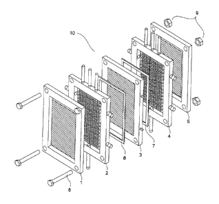
- Figure 1 illustrates an exploded view of a metallization reactor of
a device for
implementing the method of the invention.
- Figure 2 illustrates a view in perspective of a counter-electrode of
the device
illustrated in figure 1.
- Figure 3 illustrates a view of an inlet or outlet compartment for the
electrolyte
solution of the device illustrated in figure 1.
- Figure 4 illustrates a view in perspective of a support of a felt
element of the
CA 02839989 2013-12-19
14
device illustrated in figure 1.
Figure 5 illustrates a view in perspective of the support illustrated in
figure 4
in which a felt is inserted.
Figure 6 illustrates a device for implementing a method according to the
invention.
6. Description of one embodiment of the invention
The examples given here below are given by way of an indication and in no
way limit the scope of the present invention.
6.1 General principle of the invention
The general principle of the invention relies on a technique for manufacturing
a metallized or metallizable felt by electrodeposition of electroactive metal
ions on a
felt element according to which a solution of electroactive ions passes
through a felt
element at least in one direction and then in the other. The fact of making
the solution
flow at least once through each face of the felt gives a metallization of
homogeneous
quality.
6.2 Device for implementing the invention
A metallization device for implementing a method according to the invention
shall now be described with reference to figures 1 to 6.
Such a device comprises a metallization reactor also known as a percolation
cell 10.
As shown in figure 1, a metallization reactor comprises a stack comprising:
a first counter electrode 1;
a first inlet or outlet compartment 2 for an electrolyte solution;
a first seal 6;
CA 02839989 2013-12-19
a felt support 3;
a second seal 7;
a second inlet or outlet compartment 4 for an electrolyte solution;
a second counter electrode 5.
5 The
counter electrodes 1 and 5 are strictly identical. Only the first counter
electrode 1 is described in detail with reference to figure 2.
As shown in figure 2, such a counter electrode 1 comprises a frame 11. The
counter electrode 1 is non-corrodible under oxidation.
The frame 11 in this embodiment is essentially quadrangular. It is made out of
10 a non-conductive material and defines an internal housing 12.
The internal housing 12 houses a conductive plate 13. The conductive plate 13
is fixedly attached all along its periphery to the frame 12 in a tightly-
sealed manner.
Each corner of the frame 12 is has fastening pierced holes 14 passing through
it.
15 The
first and second inlet or outlet compartments 2 and 4 respectively are
identical. Only the first compartment 2 is described with reference to figure
3.
As shown in this figure 3, an inlet or outlet compartment 2 of this kind has a
framing 21 which, in this embodiment, is essentially quadrangular.
This framing 21 has dimensions substantially identical to those of the frame
11 of the counter-electrodes 1, 5. It is made out of a non-conductive
material. It is
crossed at each of its corners by fastening orifices 22. It defines a central
recess 23.
The central recess 23 houses a screen 27 which is fixedly attached all along
its
periphery to the framing 21.
The framing 21 is crossed by lower inlets 24 and lateral inlets 25 for
electrolyte solution, as well as upper outlets 26 for the electrolyte solution
and gas.
The outlets 26 comprise a discharge unit 261 for electrolyte solution and a
discharge
unit 262 for gas as can be seen more clearly in figure 6. It is important that
the
volume of discharge of the solution should be greater than that of the inlet
in order to
CA 02839989 2013-12-19
16
eliminate the gases formed during electrolysis. If not, the gases formed would
be
discharged at irregular intervals under the effect of the pressure exerted by
the liquid.
A pocket of gas would then be created in the upper part of the surface of the
felt,
preventing the phenomenon of electrodeposition and harming the quality of the
metallization.
As can be seen in figure 4, the felt support 3 comprises a chassis 31 which,
in
this embodiment, is essentially quadrangular.
This chassis 31 has dimensions substantially identical to those of the frame
of
the counter-electrodes 1, 5 and the framing 21 of the first and second
compartments 2
and 4. It is made out of a non-conductive material. It is crossed at each of
its corners
by fastening holes 32. It defines a central housing 33. The central housing 33
is
intended for housing the felt element 50 to be metallized as can be seen in
figure 5.
The rim of the central housing 33 is coated with a conductive band 34.
Conductive
rods 35, projecting out of the chassis 31, pass through two opposite sides of
the frame
31 until they come into contact with the conductive band 34. The conductive
band 34
and the rods 35 are preferably made out of a same conductive metallic
material, for
example copper.
The seals 6 and 7 are identical. They are made out of a non-conductive
material resistant to wear and tear and to repeated contact with an
electrolyte solution
and with electrodeposition reactions, and are made for example of rubber.
Their
implementation prevents the electrodeposition of metal ions on the conductive
band
34.
The metallization reactor 10 is assembled as follows.
The following are stacked respectively on the first counter-electrode 1: the
first compartment 2, the first seal 6, the support 2 within which the felt to
be
metallized 50 will have been preliminarily inserted, the second seal 7, the
second
compartment 4 and the second counter electrode 5. They are stacked in such a
way
CA 02839989 2013-12-19
17
that the pierced holes 14, the orifices 22 and the fastening holes 32 are
facing one
another.
Screws 8 are then introduced into the pierced holes 14, the orifices 22, and
the
fastening holes 32. The final assembly is obtained by means of bolts 9.
The screens 27 of the compartments 2 and 4 act as supports on either side of
the felt 50 to hold it in the support 3.
As shown in figure 6, the metallizing device comprises a first tank of
electrolyte solution 61.
The tank 61 is connected by a pipe 62 to a pump 63. The pump 63 is
connected by a tube 64 to a network of pipes 65. A valve 66 is interconnected
between the tube 64 and the network of pipes 65. The network of pipes 65 is
connected to the lower inlet 24 and side inlet 25 of electrolyte solution of
the first
compartment 2. The discharge elements 261 for removing electrolyte solution
from
the first compartment 2 are connected to tubes 67 which open into the tank 61.
Valves
68 are mounted on the tube 67.
The metallization device comprises a second tank of electrolyte solution 69.
The tank 69 is connected by a pipe 70 to a pump 71. The pump 71 is
connected by a tube 72 to a network of pipes 73. A valve 74 is interconnected
between the tube 72 and the network of pipes 73. The network of pipes 73 is
connected to the lower inlet 24 and lateral inlet 25 for the electrolyte
solution of the
second compartment 4. The discharge elements 261 for removing electrolyte
solution
from the second compartment 4 are connected to tubes 75 which open into the
tank
69. Valves 76 are mounted on the tubes 75.
The discharge elements 262 for removing gas from the first compartment 2
and second compartment 4 are opened to the exterior.
The device comprises a means for generating an electric current (not shown),
for example a potentiostat, capable of delivering a DC current. The conductive
rods
CA 02839989 2013-12-19
18
32 and the counter-electrodes 1, 5 are electrically connected to the means for
generating an electric current.
The device also comprises means for controlling pumps, valves, the means for
generating an electric current and the polarity of the counter-electrodes (not
shown).
6.3 Implementation of a method according to the invention
The implementation of a method for treatment by metallization of a felt
according to the invention shall now be described.
Such a method comprises a step in which the felt 50 to be metallized is
inserted into the central housing 33 of the support 3. The metallization
reactor 10 is
then assembled as already explained here above.
The control means are implemented so as to open the valves 66 and 76 and
close the valves 68 and 74.
The pump 63 is put into operation in such a way that the electrolyte solution
contained in the tank 61 circulates in the pipe 62, the tube 64, the network
of pipes 65
towards the inlets 24, 25 of the first compartment 1. The electrolyte solution
then
flows in the central recess 23 of the first compartment 2 and then passes
through the
screen 27 and the felt 50 until it penetrates the central recess 23 of the
second
compartment 4. The electrolyte solution then circulates through the discharge
elements 261 and then into the tube 75 to flow into the second tank 69.
At the same time, the means for generating an electric current are
implemented so as to cause electric current to flow between the first counter
electrode
1 and the conductive band 34 via the rods 35. In this way, metal ions present
in the
electrolyte solution get deposited on a first face of the felt to be
metallized 50.
The entire electrolyte solution initially contained in the first tank 61 is
gradually shed into the second tank 69. In one variant, only a portion of this
electrolyte solution can be shed into the second tank.
CA 02839989 2013-12-19
19
As soon as the first tank 61 is empty, signifying that a first cycle has been
completed, the control means stop the pump 63, shut the valves 66 and 67 and
open
the valves 74 and 68.
Before the pump 71 is activated, the pH of the electrolyte solution contained
in the tank 69 is adjusted by the injection of a few milliliters of a solution
of sodium
hydroxide in a concentration of 10 mo1/1 or sulfuric acid in a concentration
of 1 mo1/1.
The electrolyte solution is also adjusted in electroactive metal ion salts by
a few
millimeters (m1) for concentrated solution. The pH and the concentration in
metal
ions of the electrolyte solution are therefore checked after each cycle by any
method
well known to those skilled in the art such as the use of a pH-meter,
titration of the
metal ions by pH test strips, etc.
The pump 71 is implemented so that the electrolyte solution contained in the
tank 69 flows in the pipe 70, the tube 72, the network of pipes 73 towards
inlets 24,
25 of the second compartment 4. The electrolyte solution then flows in the
central
recess 23 of the second compartment 4 and then passes through the screen 27
and the
felt 50 until it penetrates the central recess 23 of the first compartment 2.
The
electrolyte solution then flows through the discharge elements 261and then
into the
tube 67 to flow into the first tank 61.
At the same time, the means for generating an electric current are
implemented so as to make electric current flow between the second counter
electrode 5 and the conductive band 34 via the rods 35. In this way, the metal
ions
present in the electrolyte solution get deposited on the other face of the
felt to be
metallized 50.
All the electrolyte solution initially contained in the second tank 69 is
gradually shed into the first tank 61. When the second tank 69 is empty, this
signifies
the completion of a second cycle of passage. A plurality of cycles can be
implemented. The pH value and the concentration in metal ions of the
electrolyte
CA 02839989 2013-12-19
solution are readjusted between each cycle of passage. In one variant, only a
portion
of this electrolyte solution can be shed into the first tank.
In parallel with the continuous passage of the electrolyte solution into the
metallization reactor from one of the tanks to the other, the intensity of the
current
5 applied
by the means for generating a current alternates between values of zero and
non-zero.
The duration for which the intensity of the current is kept at zero between
two
impositions of current with an intensity of non-zero is computed according to
the
following relationship:
V
10 t = __ feh x 60
nd
where t, is the idle time between each imposition of current in seconds,
Vfeit is the volume of felt in cm3,
n is an integer,
d is the flow rate of the electrolyte solution in ml/min.
15 The
duration of imposition during which the intensity of the current is kept at
non-zero is determined according to the following formula:
ti = tr/2
where ti is the time of imposition of the current in seconds,
tr is the idle time between each imposition of current in seconds.
20 The
intensity of the current delivered by the means for generating an electric
current is determined according to the following formula:
= ik X V felt
where I is the intensity of the current in amperes,
ik= 0,1 A/cm3
V felt is the volume of the felt in cm3.
The flow rate in the pump 63 and 71 is determined according to the thickness
of the felt to be metallized.
CA 02839989 2013-12-19
21
When the thickness of the felt ranges from 1 to 6 millimeters, the flow rate
dmax is determined according to the following formula:
dmax = 2 x Vfe/t/ a
where dmax is expressed in ml/min,
Vfeit is the volume of the felt in cm3
a is equal to 1 min.
When the thickness of the felt ranges from 6 to 12 millimeters, the flow rate
dmax is determined according to the following formula:
dmax = V felt I a
where dmax is expressed in ml/min,
Vfeit is the volume of the felt in cm3
a is equal to 1 min.
In one variant, it is conceivable to have only one tank connected to the
metallization reactor through two pumps working alternately as explained here
above.
6.4 Examples
The following embodiments are given by way of an illustration and are not
exhaustive.
Example 1: Metallization of graphite felt by nickel
A graphite felt by Le Carbone Lorraine, reference RVG 2000, is placed in the
metallization reactor as described here above. The dimensions of the felt are
24 cm x
14 cm x 0.3 cm. The volume of the felt is approximately 100 cm3. Two 10-liter
tanks
are connected to the metallization reactor. A first tank is filled with a
solution of
nickel sulfate with an Ni2+ concentration equal to 150 mg/l. The electrolyte
solution
also contains a support electrolyte consisting of sodium sulfate with a
concentration
of 0.05 mo1/1 as well as boric acid at 0.1 mo1/1. The pH factor of this
solution is set at
CA 02839989 2013-12-19
22
5. The intensity of the current applied is computed according to the following
formula:
I = ikx V felt with ik ¨ 0.1 A/cm3.
For a felt whose volume is equal to 100 cm3, an intensity equal to 10 A is
therefore applied. The time of imposition of the current is 30 seconds
followed by an
idle time of 60 seconds. The flow rate of the electrolyte solution is kept at
100
ml/min. A cycle of passage corresponds to the passage of 10 liters of solution
from a
first tank to another, through a surface of the felt. In all, six cycles are
carried out.
Between each cycle and the next one, the pH factor of the solution is adjusted
to 5 by
the addition of a few millimeters of a solution of sodium hydroxide at 10
mo1/1. The
concentration in Ni2+ is also adjusted by the addition of a few millimeters of
a
solution of nickel sulfate with a concentration of 1 mo1/1.
Thus, a metallized felt is obtained supporting a mass of nickel equal to 8.82
g,
the thickness of the coating of the fibers by nickel being of the order of 100
nm.
Using a more concentrated solution leads to a thicker deposition and a less
flexible
felt. The total time of electrolysis is 600 min comprising 200 min of
cumulated
electrolysis time and 400 min of cumulated idle time. For a flow rate
maintained at
200 ml/min, the same result is obtained for a total electrolysis time of 300
min.
To obtain a same result with a method using a stationary flow according to the
prior art, the electrolysis time is 48 hours. It can therefore clearly be seen
that the
method according to the invention considerably reduces the time of manufacture
of a
metallized felt. This reduction of the electrolysis time considerably reduces
the
energy investment needed to arrive at a same result. The method according to
the
invention is therefore compatible with a large-scale industrial application,
contrary to
the prior art where the use is restricted to the research laboratory.
A homogenous deposit is observed throughout the surface of the felt.
CA 02839989 2013-12-19
23
Example 2: Metallization of a graphite felt with copper
Direct electrodeposition on a graphite felt results in a poor-quality deposit,
since copper does not adhere well to graphite fibers. It is therefore
necessary to carry
out a preliminary metallization of the graphite felt with nickel as described
in
example 1. For a 6 cm3 felt pre-metallized with Ni2+, the invention uses an
electrolyte
solution containing copper sulfate at 318 mg/1 (concentration of Cu2+ =
0.005mol/L),
sodium sulfate at 0.05 mo1/1 and boric acid at 0.1 molt!. The intensity of the
current
applied is computed as follows:
I = ix V felt with ik = 0,1 A/cm3.
For a 6 cm3 felt, an intensity equal to 600 mA is therefore applied. The flow
rate of the solution is maintained at 12 ml/min. The time of imposition of the
current
is about 8 seconds followed by an idle time of 15 seconds. The volume of the
tank
containing the copper solution is 1 liter (1). For a flow rate of 12 ml/min,
the time of
passage of a liter of solution through a face of the felt is 80 minutes. The
number of
cycles is four and this corresponds to a total electrolysis time of 320 min.
At the end
of each cycle, the Cu2+ concentration is readjusted to its initial value by
the addition
of 10 ml of a copper solution at 0.5 molt! in the tank. The disappearance of
blue color
of the copper ions after each cycle justifies the readjustment of the
solution.
It is furthermore quite remarkable that mathematical relationships regulating
the flow rate and the time of imposition of the current by a first
metallization can be
applied to the electrodeposition on a pre-metallized felt.
Example 3: Metallization of a graphite felt by cobalt
Metallization with cobalt requires conditions stricter than those for nickel
owing to their difference in chemical reactivity. In particular, the pH factor
must be
kept at a value of 5 to 6. The dimensions of the felt are 24 cm x 14 cm x 0.3
cm. The
volume of the felt is approximately 100 cm3. Two 10-litre tanks are connected
to the
metallization reactor. A first tank is filled with a solution of cobalt
sulfate in a
CA 02839989 2013-12-19
24
concentration in Co2+ equal to 150 mg/l. The electrolyte solution furthermore
contains a support electrolyte consisting of sodium sulfate in a concentration
0.5
mo1/1 and boric acid in a concentration of 0.1 mo1/1. The intensity of the
current
applied is 10 A. The time of imposition of the current is 30 seconds followed
by an
idle time of 60 seconds. The flow rate of the electrolyte solution is kept at
100
ml/min. Between each cycle, the pH factor of the solution is adjusted to a
value
ranging from 5 to 6 by the addition of a few milliliters of a solution of
sodium
hydroxide at 10 mo1/1. The concentration in Co2+ is also adjusted by the
addition of a
few milliliters of a solution of cobalt sulfate at 1 mo1/1. Thus, a metallized
felt is
obtained supporting a mass of cobalt of about 8 g. The thickness of the
coating of the
fibers by nickel is of the order of 200 nm. The total time of electrolysis is
600 mm,
comprising 200 min of cumulated electrolysis time and 400 min of cumulated
idle
time.
The operational conditions, especially the number of cycles that need to be
implemented to obtain an adequate quality of metallization can be determined
by
implementing optimization trials. These optimization trials are conducted in
taking
account of the embodiments described here above.
6.5 Variants
A metallized or metallizable felt obtained through the method according to the
invention can also be applied in a method for treating water polluted by
metals.
Indeed, electrodeposition on felt enables swift trapping of the metal ions
present in
wastewater or polluted groundwater tables. The patent application EP-B1-
0302891
describes a method for the treatment by electrodeposition in percolation using
graphite particles for the depollution of effluents. According to this
technique, the
water charged with pollutant ions circulates through electrodes constituted by
graphite particles subjected to electric current. However, the pressure
exerted on the
particles constituting the electrode by the movement of the electrolyte
solution causes
CA 02839989 2013-12-19
a continual displacement of these particles. The combination of high pressure
exerted
by the liquid and erosion prompted by mutual friction between the particles
leads to a
high heterogeneity of the metallized depot on the surface and inside the
electrode.
Particularly susceptible areas of deposition are rapidly formed, leading to a
clogging
5 of the electrode. These technologies were therefore abandoned after the
1980s. The
use of a felt, owing to its fiber structure and its high mechanical
resistance, averts
these phenomena of poor conductivity between particles and of clogging.
The method according to the invention can also notably be implemented for
obtaining metal foils that can be used as an electrode support, for
accumulators and
10 the fuel cells.