Note: Descriptions are shown in the official language in which they were submitted.
= CA 02840037 2013-12-19
DESCRIPTION
VEHICLE SEAT
Technical Field
[0001] The present invention relates to a vehicle seat equipped with a
headrest that supports
the head of an occupant.
Background Art
[0002] Patent Document 1 below describes a vehicle seat wherein an impact
pressure
bearing frame is disposed to the front of a seatback frame, and a lower end
portion of the
impact pressure bearing frame is fixed to the seatback frame. A headrest
support frame that
supports a headrest is joined to an upper end portion of the impact pressure
bearing frame,
and the headrest support frame is supported on the seatback frame through a
turning member
such that the headrest support frame is capable of turning.
[0003] In the event of a vehicle rear collision, the headrest is moved
(displaced) towards the
front (what is known as an "active headrest"). The occupant is suppressed from
sustaining
whiplash injury due to the headrest restraining the head of the occupant.
[0004] Note that in the event of a vehicle rear collision, it is desirable for
the head of the
occupant that is moving towards the vehicle rear under inertia to be promptly
restrained by
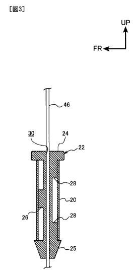
the headrest.
[0005] Patent Document 1: Japanese Utility Model Application Laid-Open (JP-U)
No.
H07-001842
SUMMARY OF INVENTION
Technical Problem
[0006] However, in this vehicle seat consideration is not given to the time
until the headrest
begins to restrain the head of the occupant (the time until the headrest
contacts the head of the
occupant). Moreover, this vehicle seat requires a mechanism to move (turn) the
headrest
towards the front, leading to a more complicated structure.
[0007] In vehicle seats that are not equipped with active headrests such as
that of the vehicle
seat described above, a stay of the headrest is supported by the seatback
frame. In the event
of a vehicle rear collision, impact force is input into the seatback frame,
and the stay oscillates
together with the headrest about a location where the stay is supported by the
seatback frame.
However, in such vehicle seats consideration is not given to the time until
the headrest begins
to restrain the head of the occupant.
[0008] In consideration of the above circumstances, an object of the present
invention is to
provide a vehicle seat capable of shortening the time until a headrest
contacts the head of an
1
=
= CA 02840037 2013-12-19
occupant in the event of a rear collision with a simple configuration.
Solution to Problem
[0009] A vehicle seat according to a first aspect includes: a seatback that
holds the upper
torso of an occupant; a headrest that is provided above the seatback, and that
supports the
head of the occupant; and a support means that is attached to the seatback and
that supports
the headrest, with bending rigidity of the support means towards the vehicle
front set lower
than bending rigidity of the support means towards the vehicle rear.
[0010] In the vehicle seat of the first aspect, the headrest is provided above
the seatback.
The support means is attached to the seatback and supports the headrest. The
headrest is
thereby attached to the seatback through the support means.
[0011] The support means is set with lower bending rigidity towards the
vehicle front than
the bending rigidity towards the vehicle rear. When impact force is input to
the seatback and
the headrest oscillates in the event of a vehicle rear collision, the headrest
is initially displaced
towards the vehicle rear under inertia, however the headrest changes direction
in a short time
and begins to be displaced towards the vehicle front side, due to the bending
rigidity of the
support means towards the vehicle rear being greater than the bending rigidity
towards the
vehicle front. There is a large displacement of the headrest towards the
vehicle front since
the bending rigidity of the support means towards the vehicle front is lower
than the bending
rigidity towards the vehicle rear. The time until the headrest contacts the
head of the
occupant can accordingly be shortened. The headrest can therefore promptly
restrain the
head of the occupant that moves towards the vehicle rear in the event of a
vehicle rear
collision. The headrest can be promptly displaced towards the side of the head
of the
occupant due to setting the bending rigidity of the support means, thereby
enabling the time
until the headrest contacts the head of the occupant to be shortened with a
simple
configuration.
[0012] A vehicle seat according to a second aspect is the vehicle seat of the
first aspect,
wherein: the bending rigidity of the support means is adjusted such that a
contact time until
the head of an occupant contacts the headrest in the event of a vehicle rear
collision is equal to
or longer than a reference time until the velocity of the headrest towards the
vehicle front
reaches a reference value or below.
[0013] In the vehicle seat of the second aspect, the bending rigidity of the
support means is
adjusted such that the contact time until the head of the occupant contacts
the headrest in the
event of a vehicle rear collision is equal to or longer than the reference
time until the velocity
of the headrest towards the vehicle front reaches the reference value or
below. A reduction
in the velocity of the head of the occupant at the point in time at which the
head contacts the
2
= CA 02840037 2013-12-19
. '
headrest (the point in time at which the headrest begins to restrain the head
of the occupant) is
accordingly suppressed. A reduction in the velocity with which the head enters
the headrest
when the head of the occupant makes contact with the headrest can thereby be
suppressed.
[0014] Note that the headrest is generally formed from a foamed material such
as urethane.
The reaction force of the headrest with respect to the head decreases with a
decrease in the
velocity with which the head enters the headrest. However, as described above,
when the
head of the occupant makes contact with the headrest, a reduction in the
velocity with which
the head enters the headrest is suppressed, thereby suppressing a reduction in
the reaction
force of the headrest with respect to the head. In the balance of the reaction
force of the
headrest on the head and the force of the head acting on the headrest, a
reduction in the
acceleration of the head of the occupant during restraint of the head by the
headrest is
suppressed since the weight of the head is fixed.
[0015] The difference between the acceleration of the shoulders of the
occupant and the
acceleration of the head of the occupant can be suppressed from increasing due
to suppressing
a reduction in the head acceleration during restraint of the head of the
occupant by the
headrest, thereby improving the whiplash injury criterion (NIC)
characteristics.
[0016] A vehicle seat according to a third aspect is the vehicle seat of
either the first aspect
or the second aspect, wherein the support means includes a support member that
projects out
from the headrest, and a retaining member that is attached to the seatback and
that is formed
with an insertion hole into which the support member is inserted, and the
vehicle seat further
includes: a front side restriction portion that restricts bending of the
retaining member towards
the vehicle front at an attachment location to the seatback of a vehicle front
side portion of the
retaining member; and a rear side restriction portion that restricts bending
of the retaining
member towards the vehicle rear and that is disposed at a location that is an
attachment
location to the seatback of a vehicle rear side portion of the retaining
member and that is also
a location on the headrest side with respect to the front side restriction
portion.
[0017] In the vehicle seat according to the third aspect, the support means
includes the
support member that is provided to the headrest and the retaining member that
is attached to
the seatback. The support member projects out from the headrest towards the
seatback side,
and is inserted into the insertion hole of the retaining member.
[0018] Note that the front side restriction portion restricts bending of the
retaining member
towards the vehicle front at the attachment location of the vehicle front side
portion of the
retaining member to the seatback. The rear side restriction portion restricts
bending of the
retaining member towards the vehicle rear and is disposed at a location that
is an attachment
location to the seatback of the vehicle rear side portion of the retaining
member and that is
3
= CA 02840037 2013-12-19
=
. '
also a location on the headrest side with respect to the front side
restriction portion. The
retaining member is accordingly supported by the rear side restriction portion
during
displacement of the headrest towards the vehicle rear, and the retaining
member is supported
by the front side restriction portion during displacement of the headrest
towards the vehicle
front. The distance from the headrest to the front side restriction portion is
moreover greater
than the distance from the headrest to the rear side restriction portion,
thereby enabling a
configuration wherein the headrest is more readily displaced towards the
vehicle front than
the headrest is displaced towards the vehicle rear. The contact time until the
headrest
contacts the head of the occupant can accordingly be set easily by varying the
position of the
front side restriction portion on the retaining member.
[0019] A vehicle seat according to a fourth aspect is the vehicle seat of the
third aspect,
wherein the front side restriction portion and the rear side restriction
portion are integrally
formed to the retaining member, and are restrained by the seatback.
[0020] In the vehicle seat of the fourth aspect, the restriction portions can
be provided whilst
suppressing an increase in costs due to forming the front side restriction
portion and the rear
side restriction portion integrally to the retaining member.
[0021] A vehicle seat according to a fifth aspect is the vehicle seat of the
fourth aspect,
wherein: the retaining member is formed in a tube shape, and a pair of the
rear side restriction
portions are provided in the retaining member axial direction; and the front
side restriction
portion is disposed in the retaining member axial direction between the pair
of the rear side
restriction portions.
[0022] In the vehicle seat of the fifth aspect, the retaining member is formed
in a tube shape,
and a pair of the rear side restriction portions are provided in the retaining
member axial
direction. The front side restriction portion is moreover disposed in the
retaining member
axial direction between the pair of the rear side restriction portions. The
retaining member
can accordingly be stably attached to the seatback since the retaining member
is attached to
the seatback at the locations of the pair of rear side restriction portions
and at the location of
the front side restriction portion.
Advantageous Effects of Invention
[0023] As described above, the vehicle seat of the present invention is
capable of shortening
the time until the headrest contacts the head of an occupant in the event of a
rear collision
with a simple configuration.
BRIEF DESCRIPTION OF DRAWINGS
[0024] Fig. 1 is a perspective view illustrating relevant portions of a
vehicle seat according
to an exemplary embodiment of the present invention, as viewed from the front
left of the
4
=
= CA 02840037 2013-12-19
vehicle.
Fig. 2 is a side view illustrating relevant portions of the vehicle seat
illustrated in Fig. 1, as
viewed from the left of the vehicle.
Fig. 3 is a cross-section illustrating a state in which a grommet employed in
the vehicle seat
illustrated in Fig. 1 is retained in a holder, as viewed from the left of the
vehicle.
Fig. 4 is a perspective view illustrating the grommet illustrated in Fig. 3.
Fig. 5 is an explanatory diagram illustrating a comparison between the
behavior of a headrest
of the present invention and the behavior of a headrest of conventional
technology in the
event of a vehicle rear collision.
Fig. 6 is a cross-section illustrating a state in which a grommet of
conventional technology is
retained in a holder, as viewed from the left of a vehicle.
Fig. 7A is an explanatory diagram illustrating the velocity with which the
head of an occupant
enters a headrest in the event of a vehicle rear collision in conventional
technology.
Fig. 7B is an explanatory diagram illustrating reaction force from a headrest
to the head
illustrated in Fig. 7A.
Fig. 7C is an explanatory diagram illustrating acceleration of the head
illustrated in Fig. 7A.
Fig. 8 is an explanatory diagram illustrating a head acceleration in the event
of a vehicle rear
collision in conventional technology.
Fig. 9 is an explanatory diagram illustrating a comparison of accelerations of
the head and the
shoulders of an occupant in the event of a vehicle rear collision in the
present invention and in
conventional technology.
DESCRIPTION OF EMBODIMENTS
[0025] Fig. 1 is a perspective view illustrating relevant portions of a
vehicle seat 10
according to an exemplary embodiment of the present invention as viewed from
the front left
of the vehicle. Fig. 2 is a side view illustrating relevant portions of the
vehicle seat 10 as
viewed from the left of the vehicle. Note that in the drawings, the arrow FR
indicates the
vehicle front, the arrow RH indicates the right of the vehicle (one vehicle
width direction
side), and the arrow UP indicates upwards.
[0026] As illustrated in Fig. 1 and Fig. 2, the vehicle seat 10 includes a
seatback 12. The
seatback 12 is disposed in an upright state at a vehicle rear end portion of a
seat cushion, not
illustrated in the drawings, that configures the vehicle seat 10. The seatback
12 is capable of
holding the upper torso of an occupant.
[0027] A seatback frame 14 is provided inside the seatback 12. The seatback
frame 14 is
coupled to a seat cushion frame, not illustrated in the drawings, that is
provided inside the seat
=
= CA 02840037 2013-12-19
'
cushion. The seatback frame 14 is provided with a pair of side frames 16 (only
the vehicle
left side frame 16 is illustrated in Fig. 1) that are bent into substantially
U-shaped
cross-section profiles. An elongated pipe shaped upper frame 18 is provided
above the side
frames 16. The upper frame 18 is bent into an inverted substantially U-shape
as viewed
from the vehicle front, and both end portions of the upper frame 18 are
respectively fixed to
the pair of side frames 16.
[0028] A pair of holders 20 (elements that may be understood to fall under the
definition of
"attachment portions") that are manufactured from metal are provided at
vehicle front side
positions of a length direction intermediate portion of the upper frame 18.
The holders 20
are fixed to the upper frame 18 by welding. The holders 20 are formed in
substantially
rectangular tube shapes, and are disposed running along the up-down direction.
[0029] As illustrated in Fig. 3, substantially rectangular tube shaped
grommets 22 that serve
as support means and retaining members and that are formed from resin are
provided inside
the pair of holders 20. Substantially rectangular plate shaped head portions
24 are provided
at upper ends of the grommets 22, and substantially four-sided pyramid shaped
stopper
portions 25 are provided at lower end portions of the grommets 22. The
grommets 22 are
retained inside the holders 20 in a state in which the head portions 24 are in
contact with
upper ends of the holders 20 and the stopper portions 25 are in contact with
lower ends of the
holders 20.
[0030] As illustrated in Fig. 4, a protrusion portion 26 serving as a front
side restriction
portion is integrally provided at a length direction intermediate portion
position of a vehicle
front portion of each of the grommets 22. Each protrusion portion 26 is formed
in a
substantially rectangular shape as viewed from the vehicle front, and projects
out from the
grommet 22 towards the vehicle front so as to contact an inner peripheral
portion of the holder
20. The
protrusion portion 26 is accordingly restrained by the holder 20 (the seatback
frame
14), and the vehicle front portion of the grommet 22 is supported by the
holder 20 at the
single location of the protrusion portion 26.
[0031] A pair of protrusion portions 28 serving as rear side restriction
portions are provided
at both length direction end portion positions of a vehicle rear portion of
each of the
grommets 22. The upper protrusion portion 28 is thereby disposed above the
protrusion
portion 26. The pair of protrusion portions 28 are formed in substantially
rectangular shapes
as viewed from the vehicle rear, and project out from the grommet 22 towards
the vehicle rear
so as to contact an inner peripheral portion of the holder 20. The protrusion
portions 28 are
accordingly restrained by the holder 20 (the seatback frame 14), and the
vehicle rear portion
of the grommet 22 is supported by the holder 20 at the 2 locations of the
protrusion portions
6
=
= CA 02840037 2013-12-19
=
28.
[0032] An insertion hole 30 is formed penetrating the grommet 22 along the
grommet 22
length direction (see Fig. 3). The insertion hole 30 is formed with a circular
cross-section
profile, and a stay 46 of a headrest 40, described later, is inserted into the
insertion hole 30.
[0033] The headrest 40 is provided above the seatback 12. The headrest 40
includes a pad
portion 42 formed from a urethane foamed material, and the pad portion 42 is
covered by a
covering skin 44. A circular rod shaped stay 46 serving as a support means and
a support
member is provided inside the pad portion 42. The stay 46 is formed in an
inverted
substantially U-shape as viewed from the vehicle front, and is bent such that
both length
direction end portions of the stay 46 are disposed towards the vehicle front
as viewed from the
left of the vehicle. A length direction intermediate portion of the stay 46 is
fixed to the pad
portion 42, and both length direction end portions of the stay 46 project out
downwards from
the headrest 40 and are inserted into the insertion holes 30 of the grommets
22. The stay 46
is moreover prevented from relative movement in the up-down direction by a
lock mechanism
(not illustrated in the drawings) that is provided to the head portions 24 of
the grommets 22.
The headrest 40 is accordingly supported by the holders 20 (the seatback frame
14) through
the grommets 22, thereby making configuration so as to support the head H of
an occupant.
[0034] As described above, the vehicle front portions of the grommets 22 are
supported by
the holders 20 at the single locations of the respective protrusion portions
26, thereby
restricting bending of the grommets 22 towards the vehicle front. The vehicle
rear portions
of the grommets 22 are respectively supported by the holders 20 at the 2
locations of the
protrusion portions 28, such that the upper protrusion portions 28 restrict
bending of the
grommets 22 towards the vehicle rear. Moreover, since the upper protrusion
portions 28 are
disposed further towards the headrest 40 side than the protrusion portions 26,
a distance from
the headrest 40 to the protrusion portions 26 is set greater than a distance
from the headrest 40
to the upper protrusion portions 28. The headrest 40 is accordingly supported
by the holders
20 (seatback frame 14) such that the bending rigidity towards the vehicle
front of the stay 46
including the grommets 22 is lower than the bending rigidity towards the
vehicle rear of the
stay 46 including the grommets 22.
[0035] The grommets 22 are retained by the holders 20 such that when impact
force is
imparted to the seatback 12 in the event of a vehicle rear collision, this
impact force is input
to the grommets 22 through the seatback frame 14 and the holders 20. Together
with the
stay 46, the headrest 40 oscillates in the vehicle front-rear direction about
the protrusion
portions 26 and the protrusion portions 28 of the grommets 22 such that the
headrest 40 is
displaced in the vehicle front-rear direction with respect to the seatback
frame 14. The
7
= =
= CA 02840037 2013-12-19
bending rigidity of the stay 46 (including the grommets 22) towards the
vehicle front is
configured lower than the bending rigidity of the stay 46 (including the
grommets 22) towards
the vehicle rear. Accordingly, during oscillation of the headrest 40 the
amplitude of the
headrest 40 towards the vehicle front is set larger than the amplitude towards
the vehicle rear,
and the period of the headrest 40 towards the vehicle front is set longer than
the period of the
headrest 40 towards the vehicle rear.
[0036] The bending rigidity of the stay 46 including the grommets 22 is
moreover adjusted
such that a time from a vehicle rear collision until the head H of the
occupant contacts the
headrest 40 (this time is referred to as the "contact time") corresponds to a
time from the
vehicle rear collision until the maximum displacement of the headrest 40
towards the vehicle
front (this time is referred to as the "peak time"). Namely, the bending
rigidity of the stay 46
including the grommets 22 is adjusted such that the contact time is equal to
or longer than a
time until the velocity of the headrest 40 towards the vehicle front reaches a
predetermined
reference value or below (this time is referred to as the "reference time"),
such that the
velocity of the headrest 40 towards the vehicle front decreases to zero in the
peak time.
[0037] The vehicle seat 10 of the present exemplary embodiment is configured
so as to
obtain the following operation. Explanation follows regarding this operation
whilst drawing
comparison with conventional technology, described below.
[0038] In the event of a vehicle rear collision, impact force towards the
vehicle front is
imparted to the seatback frame 14. This impact force is accordingly input into
the grommets
22 through the seatback frame 14 and the holders 20, and the headrest 40
oscillates about the
upper frame 18 (the seatback frame 14).
[0039] The behavior of the headrest 40 when this occurs is explained with
reference to Fig.
5. Note
that in Fig. 5, the displacement amount of the headrest 40 with respect to the
upper
frame 18 is shown against the time since the vehicle rear collision occurred.
As shown by
the solid line in Fig. 5, at the point in time of vehicle rear collision, an
impact force towards
the vehicle front is input into the upper frame 18 (seatback frame 14), and
the headrest 40 is
initially displaced towards the vehicle rear with respect to the upper frame
18 under inertia,
before being displaced towards the vehicle front.
[0040] When this occurs, there is large displacement of the headrest 40
towards the vehicle
front, with the peak time at about 60 msec, due to configuring the bending
rigidity of the stay
46 (including the grommets 22) towards the vehicle front lower than the
bending rigidity of
the stay 46 (including the grommets 22) towards the vehicle rear.
[0041] In the event of a vehicle rear collision the head H of the occupant
moves towards the
vehicle rear under inertia. During a vehicle rear collision, the head H
contacts the headrest
8
=
CA 02840037 2013-12-19
40 at the peak displacement of the headrest 40 towards the vehicle front (in
Fig. 5 the contact
time is marked by a circle) due to adjusting the bending rigidity of the stay
46 (including the
grommets 22) such that the contact time corresponds to the peak time. A
decrease in the
velocity with which the head H enters the headrest 40 is accordingly
suppressed since the
velocity of the headrest 40 towards the vehicle front is zero when the head H
makes contact
with the headrest 40.
[0042] However as illustrated in Fig. 6, in the conventional technology a pair
of protrusion
portions 26 are provided at both length direction end portions of vehicle
front portions of
grommets 22, and the bending rigidity of the stay 46 (including the grommets
22) towards the
vehicle rear and the bending rigidity of the stay 46 (including the grommets
22) towards the
vehicle front are set so as to be the same as each other. The headrest 40 is
supported by the
seatback frame 14. As illustrated by the dotted line in Fig. 5, in the
conventional technology,
in the event of a vehicle rear collision the headrest 40 is initially
displaced towards the vehicle
rear with respect to the upper frame 18, after which the headrest 40 is
displaced towards the
vehicle front. However, in the conventional technology, there is no large
displacement of the
headrest 40 towards the vehicle front since the bending rigidity of the stay
46 (including the
grommets 22) towards the vehicle rear and the bending rigidity of the stay 46
(including the
grommets 22) towards the vehicle front are set the same as each other. There
could therefore
be occasions on which the head H contacts the headrest 40 before the peak time
and when the
velocity of the headrest 40 towards the vehicle front is greater than the
reference value (see
the circle on the dotted line in Fig. 5).
[0043] Accordingly in the conventional technology, the velocity of the
headrest 40 towards
the vehicle front is reduced by the collision between the head H and the
headrest 40 when the
head H contacts the headrest 40, and the velocity with which the head H enters
the headrest
40 becomes slower (see the inside of the frame indicated by the dotted line in
Fig. 7A).
[0044] Note that the pad portion 42 of the headrest 40 is formed from a
urethane foamed
material. The load-deflection curve of the headrest 40 formed from a
comparatively soft
material such as urethane generally depends on the velocity with which the
head H enters the
headrest 40. Namely, a reaction force of the headrest 40 with respect to the
head H
decreases with a reduction in the velocity with which the head H enters the
headrest 40 (see
inside the frame indicated by the dotted line in Fig. 7B).
[0045] In the balance of the reaction force of the headrest 40 with respect to
the head H
against the force of the head H acting on the headrest 40, the acceleration of
the head H
(referred to below as "head acceleration") decreases with a reduction in the
reaction force of
the headrest 40 with respect to the head H since the weight of the head H is
fixed (see inside
9
= CA 02840037 2013-12-19
the frame indicated by the dotted line in Fig. 7C). The head acceleration of
the head H
accordingly corresponds to the curve illustrated in Fig. 8.
[0046] Accordingly, as illustrated in Fig. 9, in the conventional technology
represented by
the dotted line there are occasions when the head acceleration of the head H
decreases (falls)
when the head H is restrained by the headrest 40. However, in the present
invention
indicated by the solid line, a decrease in the head acceleration of the head H
is suppressed.
[0047] A comparison follows between whiplash injury criterion (NIC) with the
present
invention and the conventional technology, with reference to Fig. 9. Note that
in Fig. 9, the
double-dotted intermittent line indicates the acceleration of the shoulders of
an occupant, the
dotted line indicates head acceleration in the conventional technology, and
the solid line
indicates head acceleration in the present invention. In the conventional
technology, the
maximum difference between the shoulder acceleration and the head acceleration
of the head
of the occupant occurs at about 75 msec (see the arrow in Fig. 9), whereas in
the present
invention the maximum difference between the shoulder acceleration and the
head
acceleration of the head H of the occupant occurs at about 65 msec (see the
arrow in Fig. 9).
As is clear from the diagram, the maximum difference between the shoulder
acceleration and
the head acceleration of the occupant is smaller in the present invention than
in the
conventional technology. The present invention accordingly enables an improved
NIC value
over the conventional technology, since according to the NIC, the sustained
injury value
becomes smaller the smaller the difference between the acceleration of the
shoulders of the
occupant and the head acceleration over a given time following a vehicle rear
collision.
[0048] As described above, in the vehicle seat 10 the stay 46 (including the
grommets 22) is
set such that the bending rigidity towards the vehicle front is smaller than
the bending rigidity
towards the vehicle rear. Accordingly, since the bending rigidity of the stay
46 (including
the grommets 22) towards the vehicle rear is greater than the bending rigidity
towards the
vehicle front, when impact force is input into the seatback 40 in the event of
a vehicle rear
collision and the headrest 40 oscillates, the headrest 40 is initially
displaced under inertia
towards the vehicle rear, however within a short period of time the headrest
40 changes
direction and begins to be displaced towards the vehicle front. There is
moreover a large
displacement of the headrest 40 towards the vehicle front since the bending
rigidity of the stay
46 (including the grommets 22) towards the vehicle front is lower than the
bending rigidity
towards the vehicle rear. The time until the headrest 40 contacts the head H
of the occupant
can accordingly be made shorter. The head H of the occupant that has moved
towards the
vehicle rear in a vehicle rear collision can accordingly be promptly
restrained by the headrest
40.
Moreover, by setting the bending rigidity of the stay 46 including the
grommets 22, the
= CA 02840037 2013-12-19
headrest 40 can be promptly displaced towards the side of the head H of the
occupant, thereby
enabling the time until the headrest 40 contacts the head of the occupant to
be made shorter
with a simple configuration.
[0049] In the vehicle seat 10, the bending rigidity of the stay 46 (including
the grommets
22) is adjusted such that in the event of a vehicle rear collision, the
contact time until the head
H of the occupant contacts the headrest 40 corresponds to the peak time until
the maximum
displacement of the headrest 40 towards the vehicle front. A reduction in the
velocity of the
head H of the occupant at the point in time that the head H contacts the
headrest 40 (the point
in time that the headrest 40 begins to restrain the head H of the occupant) is
accordingly
suppressed. A reduction in the velocity with which the head H enters the
headrest 40 is
thereby suppressed, enabling a reduction in the head acceleration of the head
H as the
headrest 40 restrains the head H to be suppressed. An improvement in NIC can
accordingly
be achieved.
[0050] In the vehicle seat 10, the protrusion portions 26 are provided at
length direction
intermediate portions of the vehicle front portions of the respective grommets
22, and the
pairs of protrusion portions 28 are provided at both length direction end
portions of the
vehicle rear portions of the grommets 22. The upper protrusion portions 28 are
moreover
disposed further towards the headrest 40 side than the protrusion portions 26.
The grommets
22 are accordingly supported by the upper protrusion portions 28 during
displacement of the
headrest 40 towards the vehicle rear, and the retaining members are supported
by the
protrusion portions 26 during displacement of the headrest 40 towards the
vehicle front.
Since the distance from the headrest 40 to the protrusion portions 26 is
greater than the
distance from the headrest 40 to the upper protrusion portions 28,
configuration is made such
that the headrest 40 is displaced towards the vehicle front more readily than
the headrest 40 is
displaced towards the vehicle rear. The contact time until the headrest 40
contacts the head
H of the occupant can accordingly be easily set by changing the position of
the protrusion
portions 26 in the axial direction (length direction) of the grommets 22.
[0051] In the vehicle seat 10, the protrusion portions 26 and the protrusion
portions 28 are
integrally formed to the grommets 22, thereby enabling the protrusion portions
26 and the
protrusion portions 28 to be provided whilst suppressing an increase in cost.
[0052] Moreover, in the vehicle seat 10, the grommets 22 are formed from
resin, thereby
enabling the bending rigidity of the stay 46 including the grommets 22 to be
easily adjusted
by changing the material employed for the grommets 22.
[0053] Note that in the present exemplary embodiment, the bending rigidity of
the stay 46
(including the grommets 22) is adjusted such that the headrest 40 contacts the
head H of the
11
= CA 02840037 2013-12-19
'
occupant at the peak time of displacement towards the vehicle front, however
the bending
rigidity of the stay 46 (including the grommets 22) may be adjusted such that
the headrest 40
contacts the head H of the occupant at or later than the peak time of
displacement of the
headrest 40 towards the vehicle front. In such cases, the bending rigidity of
the stay 46
(including the grommets 22) can be adjusted by for example varying the
position of the
protrusion portions 26 in the length direction (axial direction) of the
grommets 22.
Moreover, in such cases the contact time until the headrest 40 contacts the
head H of the
occupant is equal to or longer than the reference time, and the head H
contacts the headrest 40
as the headrest 40 is being displaced towards the vehicle rear. A reduction in
the velocity
with which the head H of the occupant enters the headrest 40 can accordingly
be suppressed
when the head H contacts the headrest 40. A reduction in the acceleration as
the headrest 40
restrains the head H of the occupant in the event of a vehicle rear collision
can accordingly be
suppressed.
[0054] As described above, in the present exemplary embodiment the bending
rigidity of the
stay 46 (including the grommets 22) is adjusted such that the headrest 40
contacts the head H
of the occupant at the peak time. Alternatively, the bending rigidity of the
stay 46 (including
the grommets 22) may be adjusted such that the headrest 40 contacts the head H
of the
occupant prior to the peak time and at or later than the reference time. In
such cases, a
reduction in the velocity with which the head H enters the headrest 40 can be
suppressed since
the velocity of the headrest 40 towards the vehicle front as the head H
impacts the headrest 40
is the reference value or below. A reduction in the acceleration of the head H
as the headrest
40 restrains the head H of the occupant in the event of a vehicle rear
collision can accordingly
be suppressed.
[0055] Moreover, in the present exemplary embodiment the protrusion portions
26 and the
protrusion portions 28 are provided to the grommets 22. The protrusion
portions 26 and the
protrusion portions 28 may alternatively be provided to the holders 20. The
protrusion
portions 26 and the protrusion portions 28 may for example be formed by
bending the holders
20.
[0056] In the present exemplary embodiment, the protrusion portions 26 and the
protrusion
portions 28 are integrally provided to the grommets 22. Alternatively, the
protrusion
portions 26 and the protrusion portions 28 may be provided to the grommets 22
as separate
bodies. In such cases, the bending rigidity of the stay 46 including the
grommets 22 can be
easily adjusted by changing the shapes and the material of the protrusion
portions 26 and the
protrusion portions 28.
[0057] Moreover, in the present exemplary embodiment the pairs of protrusion
portions 28
12
= CA 02840037 2013-12-19
are provided at positions at both length direction end portions of the vehicle
rear portions of
the grommets 22. Configuration may alternatively be made wherein the
protrusion portions
28 are provided to the entire faces of the vehicle rear portions of the
grommets 22. The
number of the protrusion portions 28 may also be set as appropriate. Namely,
it is sufficient
that the protrusion portions 28 are provided so as to be disposed towards the
headrest 40 side
with respect to at least the protrusion portions 26.
[0058] In the present exemplary embodiment, configuration is made wherein the
stay 46 of
the headrest 40 is supported by the holders 20 of the seatback frame 14
through the grommets
22, however the headrest 40 may be configured so as to function as what is
known as an
active headrest.
13