Note: Descriptions are shown in the official language in which they were submitted.
CA 02840157 2013-12-20
1
DESCRIPTION
TITLE OF THE INVENTION: GRINDSTONE TOOL AND METHOD FOR
MANUFACTURING SAME
TECHNICAL FIELD
[0001]
The present invention relates to a grindstone tool and
a method for manufacturing the same, which improve the grinding
performance by properly setting the surface profile of a base
metal.
BACKGROUND ART
[0002]
The grinding process is a process for shaping or finishing
a workpiece by providing a grindstone tool with certain cutting
and feeding amounts while rotating the grindstone tool at a high
speed. As the grindstone tool used for such grinding process,
a grindstone tool in which abrasive grains are affixed on a base
metal by an electro-deposition method utilizing the principles
of electroplating has generally been known.
[0003]
In addition, in the above-described grindstone tool, the
grinding precision (the surface roughness of the workpiece) can
be improved by reducing the size of the abrasive grains.
Reducing the size of the abrasive grains, however, also reduces
the capacity of chip pockets formed between the abrasive grains.
If the capacity of the chip pockets is reduced as described above,
chips, which are produced by grinding, are easily stuck in the
chip pockets, and may cause the clogging of the chip pockets.
[0004]
For this reason, a grindstone tool capable of grinding
with high precision by preventing chip pockets from clogging
CA 02840157 2013-12-20
2
with chips has conventionally been provided. Such a
conventional grindstone tool is disclosed for example in Patent
Document 1.
PRIOR ART DOCUMENT
PATENT DOCUMENT
[0005]
Patent Document 1: Japanese Patent Application Publication No.
2003-25230
SUMMARY OF THE INVENTION
PROBLEMS TO BE SOLVED BY THE INVENTION
[0006]
= In the conventional grindstone tool, a plurality of
recesses are formed in a lattice pattern or a mesh pattern in
a grinding surface. With this, chips produced by grinding are
discharged into the plurality of recesses, so that the chip
pockets are prevented from clogging.
[0007]
Here, the conventional grindstone tool is formed in a disk
shape and the grinding surface thereof is formed in a planar
shape. At the time of grinding, the grindstone tool is swung
in a radial direction of a workpiece while being rotated about
the center axis thereof in a state where the planar grinding
surface is entirely brought in contact with the surface to be
ground of the workpiece. With this, although the plurality of
recesses are arranged in a lattice pattern or a mesh pattern
in the conventional grindstone tool, it is possible to
satisfactorily obtain a desired grinding precision without
particularly specifying the arrangement of these recesses.
[0008]
Meanwhile, there is also a grindstone tool formed in a
CA 02840157 2013-12-20
3
columnar or cylindrical shape. In the case of such a grindstone
tool formed in a columnar or cylindrical shape, like a so-called
grinding wheel, the grindstone tool is rotated about the center
axis thereof in a state where a part of the grinding surface
is brought in contact with the surface to be ground of a workpiece.
For this reason, if recesses are arranged simply in a lattice
pattern or a mesh pattern in the grinding surface, unevenness
occurs in the movements in position of the recesses at the time
of grinding. Accordingly, there is a fear that chip pockets
cannot be sufficiently prevented from clogging with chips.
[0009]
Therefore, the present invention has been made for
solving the above-described problem and has an object to provide
a grindstone tool and a method for manufacturing the same, the
grindstone tool having improved chip discharge characteristic
to thereby prevent chip pockets from clogging with chips and
to be capable of grinding with high precision.
MEANS FOR SOLVING THE PROBLEMS
[0010]
A grindstone tool according to a first invention for
solving the above-described problem is characterized in that
the grindstone tool comprises: dimples formed in an external
peripheral surface of a base metal such that the same number
of the dimples are scattered in a circumferential direction of
the external peripheral surface at any position in a width
direction of the external peripheral surface; a grinding
surface formed by affixing a plurality of abrasive grains on
the external peripheral surface by using a plating layer; and
recesses into which chips produced by grinding with the abrasive
grains are to be discharged, the recesses being formed by
CA 02840157 2015-05-25
31705-8
4
recessing portions corresponding to the dimples in the grinding
surface.
[0011]
A grindstone tool according to a second invention for
solving the above-described problem is characterized in that
opening portions of the dimples are formed to be open to a
downstream side in a grindstone rotation direction.
[0012]
A method for manufacturing a grindstone tool according
to a third invention for solving the above-described problem
is characterized in that the method comprises: forming dimples
in an external peripheral surface of a base metal such that the
same number of the dimples are scattered in a circumferential
direction of the external peripheral surface at any position
in a width direction of the external peripheral surface; forming
a grinding surface by affixing a plurality of abrasive grains
on the external peripheral surface by using a plating layer;
and forming recesses into which chips produced by grinding with
the abrasive grains are to be discharged, by recessing portions
corresponding to the dimples in the grinding surface.
CA 02840157 2015-10-29
31705-8
4a
[0012a]
An embodiment of the present invention relates to a
grindstone tool comprising: dimples formed in an external
peripheral surface of a base metal such that the same number of
the dimples are scattered in a circumferential direction of the
external peripheral surface at any position in a width
direction of the external peripheral surface, the dimples being
arranged at a predetermined pitch in an entire region in the
width direction of the external peripheral surface; a grinding
surface formed by affixing a plurality of abrasive grains on
the external peripheral surface by using a plating layer; and
recesses into which chips produced by grinding with the
abrasive grains are to be discharged, the recesses being formed
by recessing portions corresponding to the dimples in the
grinding surface, wherein the recesses are recessed obliquely
to correspond to opening portions of the dimples which are open
to a downstream side in a grindstone rotation direction.
EFFECT OF THE INVENTION
[0013]
Therefore, in the grindstone tool according to the
present invention, the recesses, which correspond to the
dimples scattered on the external peripheral surface of the
base metal, are formed in the grinding surface. The grindstone
tool according to the present invention is thus capable of
discharging chips produced by the grinding with the abrasive
grains into the recesses, thereby improving the chip discharge
characteristics. This makes it possible to prevent chip
pockets
CA 02840157 2013-12-20
between the abrasive grains from clogging with chips, and to
thus perform grinding with high precision.
[0014]
Moreover, in the method for manufacturing a grindstone
tool according to the present invention, when the grinding
surface is formed on the external peripheral surface of the base
metal on which the dimples are scattered, the recesses, into
which chips produced by the grinding with the abrasive grains
22 are to be discharged, can be formed by recessing the portions
corresponding to the dimples in the grinding surface. This makes
it possible to easily manufacture a grindstone tool excellent
in grinding performance.
BRIEF DESCRIPTION OF THE DRAWINGS
[0015]
[Fig. 1] Fig. 1 is a side view of a grindstone tool according
to one embodiment of the present invention.
[Fig. 2] Fig. 2 is a diagram showing how a workpiece is ground
by using the grindstone tool.
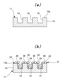
[Fig. 3] Parts (a) and (b) of Fig. 3 are cross-sectional views
sequentially showing a method for manufacturing a grindstone
tool according to one embodiment of the present invention.
[Fig. 4] Fig. 4 is a diagram showing an arrangement of dimples
formed in a base metal.
[Fig. 5] Fig. 5 is a diagram showing an arrangement of inclined
dimples formed in a base metal.
[Fig. 6] Fig. 6 is a transverse cross-sectional view of a
grindstone tool having a grinding surface in which the inclined
recesses are formed.
MODES FOR CARRYING OUT THE INVENTION
[0016]
= CA 02840157 2013-12-20
6
Hereinafter, a grindstone tool and a method for
manufacturing the same according to the present invention will
be described in detail by using the drawings.
EMBODIMENTS
[0017]
As shown in Fig. 1, a grindstone tool 1 has a structure
having a grinding surface 21 on an external peripheral portion
of a columnar base metal 11. Specifically, the base metal 11
includes a small-diameter portion 12 on the base end side and
a large-diameter portion 13 on the front end side. The
large-diameter portion 13 has a larger diameter than that of
the small-diameter portion 12. The aforementioned grinding
surface 21 is formed on an external peripheral surface 13a of
the large-diameter portion 13. The grinding surface 21 is formed
such that abrasive grains 22 having a small grain size are
scattered on the grinding surface 21 by an electro-deposition
method utilizing the principles of electroplating.
[0018]
In addition, when a grinding process (or a trimming
process) is performed, the grindstone tool 1 is fed in a
direction orthogonal to the axis thereof while the grindstone
tool 1 is rotated about the axis, as shown in Fig. 2. In this
way, the grinding process can be performed on a workpiece W.
[0019]
Next, a method for manufacturing the grindstone tool 1
will be described in detail by using Fig. 3 and Fig. 4.
[0020]
First, as shown in Part (a) of Fig. 3, a plurality of
dimples 14 are formed in a regular pattern in the external
peripheral surface 13a of the base metal 11. Note that the
CA 02840157 2013-12-20
7
dimples 14 are formed to extend toward the axis of the base metal
11 by a cutting process using a drill or the like, and opening
portions of the dimples 14 are open outward in a radial direction
of the base metal 11. In addition, the dimples 14 are dimensioned
to have inner diameters sufficiently larger than the diameters
of the abrasive grains 22.
[0021]
Specifically, as shown in Fig. 4, the dimples 14 are formed
at a predetermined pitch P1 in a width direction of the external
peripheral surface 13a (a width direction of the grinding
surface 21) , and also formed at a predetermined pitch 22 in a
circumferential direction of the external peripheral surface
13a (a circumferential direction of the grinding surface 21) .
Moreover, the dimples 14 are arranged at the aforementioned
pitches P1 and P2 such that the dimples 14 are arranged with
no gap in the entire region in the width direction of the external
peripheral surface 13a, and such that the same number of the
dimples 14 are scattered in the circumferential direction at
any position in the width direction of the external peripheral
surface 13a.
[0022]
Next, as shown in Part (b) of Fig. 3, plating is performed
on the external peripheral surface 13a of the base metal 11 to
form a plating layer 23, and the abrasive grains 22 are affixed
on the entire region of the external peripheral surface 13a
including the surfaces of the dimples 14 with the plating layer
23. In this way, a grinding surface 21 is formed on the external
peripheral surface 13a of the base metal 11.
[0023]
In this process, gaps are formed between the affixed
CA 02840157 2013-12-20
8
abrasive grains 22 in the grinding surface 21. The gaps form
chip pockets 26, and portions corresponding to the dimples 14
of the base metal 11 are recessed relative to the other portions.
The portions thus recessed form recesses 24.
[0024]
Accordingly, as shown in Fig. 2, when the workpiece W is
ground by using the grindstone tool 1, the surface to be ground
of the workpiece W is ground with the abrasive grains 22 of the
grinding surface 21. Chips produced by the grinding with the
abrasive grains 22 are discharged into the chip pockets 26 and
also discharged into the recesses 24.
[0025]
In addition, the recesses 24 are formed in portions
corresponding to the dimples 14 of the base metal 11. For this
reason, the recesses 24 are not only arranged at the pitches
P1 and P2 on the grinding surface 21, but also arranged such
that the recesses 24 are arranged with no gap in the entire region
in the width direction of the grinding surface 21, and such that
the same number of the recesses 24 are scattered in the
circumferential direction at any position in the width
direction of the grinding surface 21. This makes it possible
to cause the recesses 24 to face the surface to be ground of
the workpiece W evenly in the width direction and the
circumferential direction. Therefore, chips can be easily
discharged into the recesses 24.
[0026]
As a result, even if the grain size of the abrasive grains
22 is small and a sufficient amount of protrusion thereof cannot
be secured, that is, even if the capacity of the chip pockets
26 is very small, the chip pockets 26 can be prevented from
CA 02840157 2013-12-20
9
clogging with chips. Accordingly, the workpiece W can be ground
with high precision by using the grindstone tool 1.
[0027]
In the above-described grindstone tool 1, the dimples 14,
whose opening portions are open outward in the radial direction
of the base metal 11, are scattered on the base metal 11.
Alternatively, as shown in Fig. 5 and Fig. 6, inclined dimples
15 whose opening portions are open to the downstream side in
a rotation direction of the grindstone tool 1 may be scattered
on the base metal 11.
[0028]
In this way, as shown in Fig. 6, portions corresponding
to the inclined dimples 15 of the base metal 11 are recessed
in an oblique direction to the axis of the base metal 11 relative
to the other portions in the grinding surface 21. The portions
thus recessed form inclined recesses 25. Accordingly, forming
the inclined recesses 25 in the grinding surface 21 makes it
easier to discharge chips from the inside of the inclined
recesses 25. Therefore, the chip discharge characteristics can
be further improved.
[0029]
Note that in the above-described embodiments, the
abrasive grains 22 and the plating layer 23 are disposed also
inside the recesses 24, 25; however, the abrasive grains 22 and
the plating layer 23 may not necessarily disposed inside the
recesses 24, 25 because the insides of the recesses 24, 25 are
not involved in the grinding.
[0030]
Therefore, in the grindstone tool 1 according to the
present invention, the recesses 24, 25, which correspond to the
CA 02840157 2013-12-20
dimples 14, 15 scattered on the external peripheral surface 13a
of the base metal 11, are formed in the grinding surface 21.
The grindstone tool 1 according to the present invention is thus
capable of discharging chips produced by the grinding with the
abrasive grains 22 into the recesses 24, 25, thereby improving
the chip discharge characteristics. This makes it possible to
prevent the chip pockets 26 from clogging with chips, and to
thus perform grinding with high precision.
[0031]
Moreover, in the method for manufacturing the grindstone
tool 1 according to the present invention, when the grinding
surface 21 is formed on the external peripheral surface 13a of
the base metal 11 on which the dimples 14, 15 are scattered,
the recesses 24, 25, into which chips produced by the grinding
with the abrasive grains 22 are to be discharged, can be formed
by recessing the portions corresponding to the dimples 14, 15
in the grinding surface 21. This makes it possible to easily
manufacture the grindstone tool 1 excellent in chip discharge
characteristics.
INDUSTRIAL APPLICABILITY
[0032]
The present invention is applicable to a grindstone tool
and a method for manufacturing the same which attempt to improve
grinding performance by adjusting intervals and tip height of
abrasive grains to increase the capacity of chip pockets.