Note: Descriptions are shown in the official language in which they were submitted.
CA 02840316 2013-12-23
WO 2013/001502 PCT/1B2012/053313
- 1 -
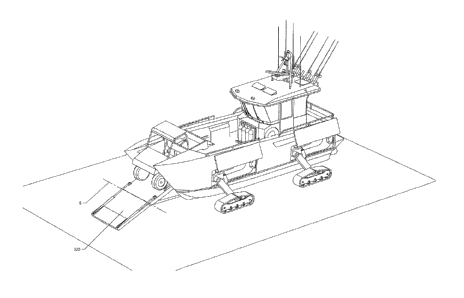
A VESSEL
TECHNICAL FIELD
The present invention relates to improvements in or relating to a vessel.
More particularly but not exclusively it relates to a vessel with a
reconfigurable
superstructure.
More particularly but not exclusively it relates to an amphibious vessel with
a
reconfigurable superstructure.
More particularly but not exclusively it relates to a vessel with a deployable
ramp for
loading of the vessel.
More particularly but not exclusively it relates to an amphibious vessel with
deployable
motive pods.
BACKGROUND OF THE INVENTION
Marine vessels are vehicles designed for transporting persons and/or goods
over a
body of water. Vessels are used for a variety of purposes such as recreation,
fishing, or cargo
transportation. Such vessels are normally designed optimally be for their
particular
application. In some situations it is desirable to have a vessel that is more
versatile in that is
can be used for more than one purpose. In such a situation it is beneficial
that the vessel is
designed and configured to suit all its intended purposes. Due to the specific
nature of some
applications, designing a vessel for multiple applications can be problematic.
It is beneficial to
have a vessel that is reconfigurable to more readily allow it to be configured
for a variety of
specific applications.
In some applications it is desirable to transport an auxiliary vehicle over a
body of
water. Traditionally this has been done using large ferries and barges with
suitable loading
ramps and/or doors. In some situations it is desirable that several vehicles
can be transported
on a smaller vessel.
So called landing craft are well known and have been used extensively through
history
for carrying small numbers of people and vehicles for deploying on land.
Various systems are
employed for allowing ingress and egress of vehicles and persons from such
vessels such as
ramps and/or doors. Some such landing craft, in addition to being waterborne,
also include
systems for allowing the vessel to move across land by means such as tracks or
wheels. Many
of such vessels were used for military applications and are configured for the
specific purpose
of deploying people on a piece of land, for example amphibious armoured
personal carriers.
CA 02840316 2015-05-20
- 2 -
There is a need for a vessel suitable for carrying and deploying an auxiliary
vehicle
that is also suitable for other applications.
OBJECT OF AN ASPECT OF THE INVENTION
It is an object of an aspect of the present invention to provide a vessel
capable of
being reconfigured to improve its suitability for a variety of applications.
It is an alternative object of an aspect of the present invention to provide
improvements in or relating to vessels which overcomes or at least ameliorates
some of the
abovementioned disadvantages or which at least provides the public with a
useful choice
In this specification, where reference has been made to external sources of
information, including patent specifications and other documents, this is
generally for the
purpose of providing a context for discussing the features of the present
invention. Unless
stated otherwise, reference to such sources of information is not to be
construed, in any
jurisdiction, as an admission that such sources of information are prior art
or form part of
the common general knowledge in the art.
SUMMARY OF THE INVENTION
In a first aspect the present invention may broadly be said to be a vessel
comprising:
a hull,
at least one super structure configured to at least in part translate relative
to
said hull between a first position and at least one other position (herein
after "second
condition"),
wherein said at least one superstructure in said first condition at least in
part
defines a first zone suitable for accommodating at least one person and/or
vehicle,
and wherein said at least one superstructure in said second condition at least
in
part defines a second zone suitable for accommodating at least one person
and/or
vehicle.
Preferably the at least one superstructure at least in part separates the
first and
second zones.
Preferably the vessel's centre of mass is aft of mid-ship in the first
condition and
forward of mid-ship in the second position.
Alternatively the vessel includes a balancing means suitable for ensuring the
vessel's
centre of mass remains substantially constant.
CA 02840316 2013-12-23
WO 2013/001502 PCT/1B2012/053313
- 3 -
Preferably the centre of mass is maintained proximate an axis extending
vertically
through the centroid of the vessel.
Preferably the vessel has a deck.
Preferably the at least one superstructure is at least in part supported on
said deck
Preferably the at least one superstructure at least in part forms a housing.
Preferably the housing is configured to accommodate at least one person.
Preferably the housing includes one or more means for controlling the vessel's
movement.
Preferably the superstructure is a combination of any one or more of the
following,
a pilot housing,
a cabin, and
a structure supporting and/or enclosing the helm.
Preferably the at least one super structure is configured to at least in part
translate
along an axis.
Preferably the axis extends between the bow and stern of the vessel.
Preferably the axis is parallel the longitudinal direction of the vessel.
Preferably the first and second zones are at least in part defined on the
deck.
Preferably the first zone is located more proximate the bow of the vessel than
the
second zone.
Preferably the first zone is located at or proximate the bow of the vessel.
Preferably the vessel includes a ramp and/or door (hereinafter "ramp")
Preferably the ramp is located proximate the bow of the vessel.
Alternatively the ramp is located proximate the stem of the vessel.
Preferably the ramp is configured to facilitate ingress and/or egress of
persons and/or
matter from the vessel.
Preferably the ramp is configured to facilitate ingress and/or egress of
persons and/or
matter from the first zone.
Preferably the ramp is configured to allow ingress and/or egress of persons
and/or
matter from the second zone.
Preferably the ramp forms part of the hull.
Preferably the ramp forms part of the bow of the hull.
Preferably the vessel is amphibious
Preferably the vessel includes tracks suitable for supporting and transporting
the vessel
over land.
CA 02840316 2013-12-23
WO 2013/001502 PCT/1B2012/053313
- 4 -
Preferably the tracks are deployable from a retracted position within the
vessel's hull.
Preferably the first zone is fully defined when the superstructure is in said
first
condition and the second zone is fully defined when the superstructure is in
the second
condition.
Preferably the first and second zones are partially defined when said
superstructure is
between said first and second conditions.
Preferably any superstructure and/or zone configured to accommodate at least
one
person and/or vehicle is also suitable for accommodating alternative cargo
and/or goods.
Preferably, the vessel further comprises
a ramp arrangement extending between the demi-hullls,
the ramp arrangement presenting an outer surface;
the ramp arrangement being moveable at least between
a retracted position in which the vessel is rendered seaworthy, and
a deployed position in which the ramp arrangement facilitates ingress
and egress from the vessel;
wherein when the ramp arrangement is in its retracted position, the outer
surface of
the ramp arrangement is configured to complement the configuration of the
partly
formed demi-hulls to form a seaworthy outer hull configuration presenting a
plurality
of fully formed demi-hulls.
Preferably, when the ramp arrangement is in its retracted position, the outer
surface of
the ramp arrangement complements the configuration of the partly formed demi-
hulls to
present at least one or more wave piercing surfaces.
Preferably, at least one or more outer surfaces of the ramp arrangement will
be
coplanar with a surface of at least one of the partly formed demi-hulls when
the ramp
.. arrangement is in its retracted position.
Preferably, at least one or more outer surfaces of the ramp arrangement will
be
coplanar with a surface of both of the partly formed demi-hulls when the ramp
arrangement is
in its retracted position.
Preferably, the ramp arrangement presents a pathway for ingress and egress
from the
vessel in its deployed position.
Preferably, when the ramp arrangement is in its retracted position, the ramp
arrangement interacts with the partly formed demi-hulls to present a
waterproof outer hull.
Preferably, the ramp arrangement is movable between its retracted and its
deployed
position at least partially by pivotal movement.
CA 02840316 2013-12-23
WO 2013/001502 PCT/1B2012/053313
- 5 -
Preferably, the ramp arrangement is movable between its retracted and its
deployed
position at least partially by pivotal movement about a pivoting arrangement.
Preferably, the ramp arrangement is movable between its retracted and its
deployed
position at least partially by pivotal movement about a pivoting arrangement
at or towards a
lower edge of the ramp arrangement.
Preferably, the ramp arrangement is movable between its retracted and its
deployed
position at least partially by linear movement.
Preferably, the ramp arrangement is movable between its retracted and its
deployed
position at least partially by linear movement of a slider arrangement.
Preferably, the ramp arrangement is movable between its retracted and its
deployed
position at least partially by linear movement at or towards a lower edge of
the ramp
arrangement.
Preferably, the ramp arrangement is at least partially- planar in
configuration.
Preferably, the ramp arrangement comprises demi-hull part formations for
complementary engagement with the partly formed demi-hulls to present fully
formed demi ¨
hulls.
Preferably, in its deployed position, the ramp arrangement presents a
substantially
horizontal surface to facilitate ingress and egress from the vessel.
Preferably, in its deployed position, the ramp arrangement facilitate ingress
and egress
from the vessel by one or more selected from:
a vehicle;
a vessel;
a person; any
any other matter.
Preferably, the ramp arrangement comprises a plurality of sections movable
relative to
each other.
Preferably, the ramp arrangement comprises a bow section and a cover section.
Preferably, the demi-hull part formations extend from the bow section.
Preferably, the bow section and the cover section are pivotably movable
relative to
each other.
Preferably, the cover section and the bow section are configured to be movable
relative to each other between a
folded position in which cover section is at an acute angle to the bow
section; and
CA 02840316 2013-12-23
WO 2013/001502 PCT/1B2012/053313
- 6 -
an aligned position in which the cover section and a the bow section present a
substantially aligned pathway for ingress and egress to and from the vessel.
Preferably, the cover section and the bow section are configured to move to
their
folded position when the ramp arrangement is in its retracted position.
Preferably, the cover section and the bow section are configured to move to
their
aligned position when the ramp arrangement is in its deployed position.
Preferably, the cover section is configured to cover at least part of the bow
of the
vessel.
Preferably, the ramp arrangement seals against the bow of the vessel in its
retracted
position.
Preferably, the ramp arrangement in its deployed position is configured to
extend to a
position in which the foremost point of the ramp arrangement is below the
water line of the
vessel.
Preferably, the vessel is an amphibious vessel.
Preferably, the vessel comprises at least one set of deployable wheels.
Preferably, the vessel comprises a plurality of sets of deployable wheels.
Preferably, at least one set of deployable wheels is associated with a track
arrangement.
Preferably, each set of deployable wheels are associated with a track
arrangement.
Preferably, the vessel comprises a deck, and the lower edge of said bow
section is
located substantially in line with the deck.
Preferably, at least one of the deny-hulls comprises an upper surface.
Preferably, at least one of the demi-hulls comprises an upper surface, thereby
enclosing an enclosed region within the demi-hull.
Preferably, the enclosed region is water tight.
Preferably, each demi-hull comprises an upper surface enclosing a watertight
enclosed
region.
Preferably, the vessel comprises a deck extending between the demi hulls.
Preferably, at least one of the demi-hulls comprises a recess in its upper
extending at
least partially into its upper surface, and aligned with the level of the deck
to thereby increase
the deck width of the vessel.
Preferably, the width of the pathway provided by the ramp arrangement in its
deployed position is wider than the deck.
CA 02840316 2013-12-23
WO 2013/001502 PCT/1B2012/053313
- 7 -
Preferably, the width of the pathway provided by the ramp arrangement in its
deployed position is wider than the deck, and equal to or smaller than the
extended deck
width of the vessel.
Preferably, the amphibious vessel comprises
at least one or more deployable motive pods, each motive pod being associated
with a
hull recess in the hull, and movable between
a deployed position in which the amphibious vessel is movable on
the motive pods over land; and
a stowed position in which the motive pod are stowed for use
while the amphibious vessel is travelling over water;
at least one or more deployment mechanisms configured for moving the motive
pod
between their deployed position and their stowed position, each deployment
mechanism associated with at least one motive pod and comprising
a horizontal translation mechanism configured to move the motive pod
between
a proximal condition in which the motive pod is at least partially
received into recess; and
a distal condition in which the motive pod is located distally of the
proximal condition;
a lowering mechanism for moving the motive pod between
a lower position in which the lowest point of the motive pod is lower
than the hull, and
an upper position in which the motive pod is located in a position
suitable for lateral movement into the hull recess.
Preferably, each motive pod comprises one or more wheels.
Preferably, the each motive pod comprises an associated track arrangement.
Preferably, each track arrangement comprises an endless track formation.
Preferably, the lowering mechanism is configured to move a motive pod
pivotally
about a pivot axis.
Preferably, the hull presents at least a pair of sides with at least one hull
recess
extending into each of the sides.
Preferably, the amphibious vessel comprises a plurality of motive pods.
Preferably, the amphibious vessel comprises at least one or more deployment
mechanisms.
CA 02840316 2013-12-23
WO 2013/001502 PCT/1B2012/053313
- 8 -
Preferably, a deployment mechanism is associated with each motive pod.
Alternately, one deployment mechanism is associated with a plurality of motive
pods.
Preferably, at least one motive pod includes a track arrangement.
Preferably, each motive pod includes a track arrangement.
Preferably, the horizontal translation mechanism comprises a moving member
movable on a track.
Preferably, the horizontal translation mechanism comprises a moving member
linearly
movable on a track arrangement.
Preferably, the track arrangement is a telescopic arrangement.
Preferably, the horizontal translation mechanism comprises a linear actuator.
Preferably, the linear actuator is a hydraulic ram.
Preferably, the lowering mechanism comprises a linear actuator for pivoting a
pivot
member about a pivot axis.
Preferably, the pivot axis is oriented horizontally.
Preferably, the pivot axis is oriented horizontally and substantially
transversely to the
length of the amphibious vessel.
Preferably, the linear actuator is a hydraulic ram.
Preferably, the moving member comprises one or more end stop formations for
preventing the moving member moving off the ends of the guide arrangement.
Preferably, the deployment mechanism comprises a locking mechanism for locking
the
moving member in position.
Preferably, the locking mechanism is operable from the deck of the vessel.
Preferably, the locking mechanism is manually operable from the deck of the
vessel.
Preferably, the locking mechanism is manually operable from the deck of the
vessel via
at least one or more hatches.
Preferably, the lowering mechanism comprises an aligning mechanism for
aligning the
motive pod with the hull recess for movement into its stowed position as the
lowering
mechanism 250 is moving from its lower position to its upper position.
Preferably, the aligning mechanism is configured for aligning the motive pod
in a
suitable position for use in its deployed position as the lowering mechanism
is moving from
its upper position to its lower position.
Preferably, the aligning mechanism comprises
a stop member;
a sliding elongate member; and
CA 02840316 2013-12-23
WO 2013/001502 PCT/1B2012/053313
- 9 -
a receiving formation configured for sliding connection with the sliding
elongate
member.
Preferably, the stop member is located on the linear actuator.
Preferably, the receiving formation is located on the pivot member, and is
configured
to receive the sliding elongate member through one selected from an aperture
and a recess in a
linearly sliding fashion.
Preferably, the receiving formation is connected to the pivot member in a
pivoting
fashion.
Preferably, the receiving formation is connected to the pivot member in a
pivoting
fashion by a pivoting joint.
Preferably, the sliding elongate member comprises a free end and a connected
end.
Preferably, the free end of the sliding elongate member is received through
the
selected from an aperture and a recess of the receiving formation.
Preferably, the connected end of the sliding elongate member is pivotally
connected to
the motive pod.
Preferably, the pivot member is pivotably connected to the motive pod.
Preferably, the pivot member is pivotably connected to the motive pod by a
pivot
joint.
Preferably, the pivot member is pivotably connected to the motive pod
asymmetrically, so that one side of the motive pod will hang downwardly under
gravity when
the motive pod is in its deployed position without contact with a floor
surface.
Preferably, when the lowering mechanism is in its lower position, the sliding
elongate
member does not make contact with the stop member.
Preferably, as the lowering mechanism is moved towards it upper position from
its
lower position by pivoting of the pivot member, the free end of the sliding
elongate member
moves closer to the stop member.
Preferably, the free end of the sliding elongate member will make contact with
the
stop member as the lowering mechanism is moved towards it upper position, to
thereby cause
the motive pod to pivot about its pivot joint to align with the hull recess
when the lowering
mechanism is in its upper position.
Preferably, the one or more motive pods has an associated drive transmission
for
driving movement of at least one wheel of the motive pods.
Preferably, the amphibious vessel comprises a control system.
CA 02840316 2013-12-23
WO 2013/001502 PCT/1B2012/053313
- 10 -
Preferably, the amphibious vessel comprises a control system for controlling
the
steering of the amphibious vehicle on land.
Preferably, the steering of the amphibious vehicle on land is controlled by
controlling
the drive to at least one wheel in a motive pod.
Preferably, the steering of the amphibious vehicle on land is controlled by
controlling
angular movement of at least one wheel in a motive pod.
Preferably, the control system controls the steering of the wheels by causing
angular
movement of at least one wheel in a motive pod.
Preferably, the control system is configured to control the drive to the
motive pod.
Preferably, the control system is configured to control the drive to one or
more track
arrangements in a motive pod.
Preferably, the control system is controlled by one or more selected from a
steering
wheel a joystick and foot pedals.
Preferably, the hull presents at least a pair of sides.
Preferably, a motive pod is associated with each side.
Preferably, the amphibious vessel comprises hull recess covers for at least
partially
covering the hull recesses at least when a motive pods are in their stowed
position.
Preferably, the hull recess covers are configured to reduce drag on the
amphibious
vessel when the vessel is moving through water.
Preferably, the hull recess covers are movable by a moving mechanism between a
covered position and an uncovered position.
Preferably, the moving mechanism is a pantographing mechanism.
The at least one hull may be a plurality of demi-hulls.
Preferably, the amphibious vessel comprises a pair of demi-hulls.
Preferably, at least one of the demi-hulls are fully formed.
Preferably, at least one of the demi-hulls are partly formed.
Preferably, the amphibious vessel comprises four hull recesses and a motive
pod
associated with each hull recess.
Preferably, the amphibious vessel comprises four hull recesses and a motive
pod with
a track arrangement associated with each hull recess.
Preferably, a pair of hull recesses are associated with each demi-hull.
Preferably, the pair of hull recesses present to an outer side of each demi-
hull.
Preferably, a front hull recess and a rear hull recess is associated with each
demi-hull.
The at least one hull may be a uni-hull.
CA 02840316 2013-12-23
WO 2013/001502 PCT/1B2012/053313
- 11 -
Preferably, the uni-hull has at least one hull recess on each side.
Preferably, the uni-hull has a pair of hull recesses on each side.
Preferably, the hull recesses are disposed at least partially above the
waterline of the
amphibious vessel when the vessel is moving through water.
Preferably, the hull recesses are disposed above the waterline of the
amphibious vessel
when the vessel is moving through water, to thereby ensure that the motive
pods are not
submerged when the vessel is moving through water.
Preferably, the amphibious vessel comprises a flushing system for flushing
water from
a fresh water source through at least one or more hull recesses.
Preferably, the flushing system comprises connector formations for connecting
the
flushing system to a fresh water source.
Preferably, the connector formations is a hose connector.
Preferably, the flushing system comprises at least one or more nozzles
suitable for
spraying the inside of at least hull recess with water from a fresh water
source when a fresh
water source is connected.
Preferably, the motive pods are coupled to hull structure on the amphibious
vessel.
Preferably, at least one motive pod comprises a suspension arrangement for
operably
at least partially reducing forces acting on the hull structure by dissipating
the energy of forces
acting on the motive pod.
Preferably, the suspension arrangement is selectable between
an engaged condition in which the suspension arrangement is operable; and
a disengaged condition in which suspension arrangement is not operable
Preferably, when the motive pods are in their deployed position, the
suspension
arrangement is selectable between
an engaged condition in which the suspension arrangement is operable; and
a disengaged condition in which suspension arrangement is reduced in
efficacy.
Preferably, when the motive pods are in their deployed position, the
suspension
arrangement is selectable between
an engaged condition in which the suspension arrangement is operable; and
a disengaged condition in which suspension arrangement is not operable.
Preferably, the suspension arrangement is selectable between its engaged and
disengaged condition by movement of the horizontal translation mechanism.
CA 02840316 2013-12-23
WO 2013/001502 PCT/1B2012/053313
- 12 -
Preferably, the horizontal translation mechanism is configured to move between
a
suspension engagement position in which the suspension arrangement is in its
engaged
condition, and a suspension disengagement position in which the suspension
arrangement is
in its disengaged condition.
Preferably, the suspension arrangement comprises a resilient member.
Preferably, the resilient member is a spring.
Preferably, the resilient member is an air spring.
Preferably, the movement of the horizontal translation mechanism to its
engaged
condition causes the coupling of the pivot member to a swing arm to thereby
engage the
suspension arrangement in its engaged condition.
Preferably, movement of the horizontal translation mechanism to its disengaged
condition causes the decoupling of the pivot member to a swing arm to thereby
disengage the
suspension arrangement to its disengaged condition.
Preferably, when the suspension arrangement is in its engaged condition, the
swing
arm is caused to engage with the resilient member when the pivot member is
pivoted in at
least one direction.
Preferably the motive pods comprises a quick release mechanism, whereby the
motive
pods are at least partially disengageable from the deployment mechanism, to
allow the motive
pods to be manually manoeuvred from the hull recesses. Preferably, the
superstructure is
.. movable by a superstructure moving mechanism.
Preferably, the superstructure is movable by a superstructure moving mechanism
that
extends along the centre line of the vessel.
Preferably, the superstructure moving mechanism comprises a chain that is
engaged by
at least one or more cogs.
Preferably, the superstructure moving mechanism comprises a chain in an
endless
loop, that is engaged by a pair of oppositely moving cogs.
In another aspect the present invention may broadly be said to be a
superstructure suitable for mounting on a vessel, the superstructure
comprising:
at least one member configured to at least in part translate relative to a
vessels hull
between a first condition and at least one other condition (herein after
"second condition"),
wherein said at least one member in said first condition at least in part
defines a first
zone in said vessel suitable for accommodating at least one person and/or
vehicle,
and wherein said at least one member in said second condition at least in part
defines a
second zone in said vessel suitable for accommodating at least one person
and/or vehicle.
CA 02840316 2013-12-23
WO 2013/001502 PCT/1B2012/053313
- 13 -
Preferably said superstructure is configured to allow it to be retro fitted to
an existing
vessel.
In an alternative aspect the present invention may broadly be said to be a
vessel
comprising:
a hull,
a deck,
first and second zones at least in part defined on said deck,
said first and second zones separated at least in part by a superstructure
configured to
translate between a first and second position.
Preferably the first zone is defined when said superstructure is in said first
condition
and said second zone is defined when said superstructure is in said second
condition.
Preferably said second zone ceases to be or is only partially defined when
said
superstructure is in said first condition.
Preferably said first zone ceases to be or is only partially defined when said
superstructure is in said second condition.
Preferably said the definition of said first and second zones is variably
dependent on
the relative position of the superstructure between the first and second
conditions.
In another aspect the present invention may broadly be said to be a vessel
comprising:
any one or more of the following superstructures
a pilot housing
a cabin
a structure supporting and or enclosing the helm
wherein said any one or more superstructures can translate relative to the
hull.
In a further aspect the present invention may broadly be said to be a method
of
configuring a vessel comprising the step of:
translating a superstructure of the vessel as herein previously described
between the first
or second condition and the other of said first or second condition to thereby
define the
first or second zones
Preferably said method of configuring the vessel comprises the further steps
of
deploying a vehicle and or passengers from said first or second zones.
In a further aspect the present invention may broadly be said to be a vessel
comprising
a plurality of partly formed demi-hulls,
CA 02840316 2013-12-23
WO 2013/001502 PCT/1B2012/053313
- 14 -
a ramp arrangement extending between the demi-hullls,
the ramp arrangement presents an outer surface;
the ramp arrangement being moveable at least between
a retracted position in which the vessel is rendered seaworthy,
and
a deployed position in which the ramp arrangement facilitates
ingress and egress from the vessel;
wherein when the ramp arrangement is in its retracted position, the outer
surface of the ramp arrangement is configured to complement the
configuration of the partly formed demi-hulls to form outer hull configuration
presenting a plurality of seaworthy fully formed demi-hulls.
Preferably, when the ramp arrangement is in its retracted position, the outer
surface of
the ramp arrangement complements the configuration of the partly formed demi-
hulls to
present at least one or more wave piercing surfaces.
Preferably, at least one or more outer surfaces of the ramp arrangement will
be
coplanar with a surface of at least one of the partly formed demi-hulls when
the ramp
arrangement is in its retracted position.
Preferably, at least one or more outer surfaces of the ramp arrangement will
be
coplanar with a surface of both of the partly formed dcmi-hulls when the ramp
arrangement is
in its retracted position.
Preferably, the ramp arrangement presents a pathway for ingress and egress
from the
vessel in its deployed position.
Preferably, when the ramp arrangement is in its retracted position, the ramp
arrangement interacts with the partly formed demi-hulls to present a
waterproof outer hull.
Preferably, the ramp arrangement is movable between its retracted and its
deployed
position at least partially by pivotal movement.
Preferably, the ramp arrangement is movable between its retracted and its
deployed
position at least partially by pivotal movement about a pivoting arrangement.
Preferably, the ramp arrangement is movable between its retracted and its
deployed
position at least partially by pivotal movement about a pivoting arrangement
at or towards a
lower edge of the ramp arrangement.
Preferably, the ramp arrangement is movable between its retracted and its
deployed
position at least partially by linear movement.
CA 02840316 2013-12-23
WO 2013/001502 PCT/1B2012/053313
- 15 -
Preferably, the ramp arrangement is movable between its retracted and its
deployed
position at least partially by linear movement of a slider arrangement.
Preferably, the ramp arrangement is movable between its retracted and its
deployed
position at least partially by linear movement at or towards a lower edge of
the ramp
arrangement.
Preferably, the ramp arrangement is at least partially planar in
configuration.
Preferably, the ramp arrangement comprises demi-hull part formations for
complementary engagement with the partly formed demi-hulls to present fully
formed demi ¨
hulls.
Preferably, in its deployed position, the ramp arrangement presents a
substantially
horizontal surface to facilitate ingress and egress from the vessel.
Preferably, in i ts deployed position, the ramp arrangement facilitate ingress
and egress
from the vessel by one or more selected from:
= a vehicle;
= a vessel;
= a person; any
= any other matter.
Preferably, the ramp arrangement comprises a plurality of sections movable
relative to
each other.
Preferably, the ramp arrangement comprises a bow section and a cover section.
Preferably, the demi-hull part formations extend from the bow section.
Preferably, the bow section and the cover section are pivotably movable
relative to
each other.
Preferably, the cover section and the bow section are configured to be movable
relative to each other between a
= folded position in which cover section is at an acute angle to the bow
section;
and
= an aligned position in which the cover section and a the bow section
present a
substantially aligned pathway for ingress and egress to and from the vessel.
Preferably, the cover section and the bow section are configured to move to
their
folded position when the ramp arrangement is in its retracted position.
Preferably, the cover section and the bow section are configured to move to
their
aligned position when the ramp arrangement is in its deployed position.
CA 02840316 2013-12-23
WO 2013/001502 PCT/1B2012/053313
- 16 -
Preferably, the cover section is configured to cover at least part of the bow
of the
vessel.
Preferably, the ramp arrangement seals against the bow of the vessel in its
retracted
position.
Preferably, the ramp arrangement in its deployed position is configured to
extend to a
position in which the foremost point of the ramp arrangement is below the
water line of the
vessel.
Preferably, the vessel is an amphibious vessel.
Preferably, the vessel comprises at least one set of deployable motive pods.
Preferably, the vessel comprises a plurality of motive pods.
Preferably, at least one motive pod includes a track arrangement.
Preferably, each motive pod includes a track arrangement.
Preferably, the vessel comprises a deck, and the lower edge of said bow
section is
located substantially in line with the deck.
Preferably, at least one of the demi-hulls comprises an upper surface.
Preferably, at least one of the demi-hulls comprises an upper surface, thereby
enclosing an enclosed region within the demi-hull.
Preferably, the enclosed region is water tight.
Preferably, each demi-hull comprises an upper surface enclosing a watertight
enclosed
region.
Preferably, the vessel comprises a deck extending between the demi hulls.
Preferably, at least one of the demi-hulls comprises a recess in its upper
extending at
least partially into its upper surface, and aligned with the level of the deck
to thereby increase
the deck width of the vessel.
Preferably, the width of the pathway provided by the ramp arrangement in its
deployed position is wider than the deck.
Preferably, the width of the pathway provided by the ramp arrangement in its
deployed position is wider than the deck, and equal to or smaller than the
extended deck
width of the vessel.
Preferably, the vessel comprises at least one super structure configured to at
least in
part translate relative to one or more of said demi-hull between a first
condition and at least
one other position (herein after "second condition"),
wherein said at least one superstructure in said first condition at least in
part defines a
first zone suitable for accommodating at least one person and/or vehicle,
CA 02840316 2013-12-23
WO 2013/001502 PCT/1B2012/053313
- 17 -
and wherein said at least one superstructure in said second condition at least
in part
defines a second zone suitable for accommodating at least one person and/or
vehicle.
Preferably, the translatable superstructure is a pilot housing.
Preferably, the vessel comprises
at least one or more deployable motive pods, each wheel associated with a hull
recess
in the hull, and movable between
a deployed position in which the amphibious vessel is movable on the motive
pods over land; and
a stowed position in which the motive pods are stowed for use while the
amphibious vessel is travelling over water;
at least one or more deployment mechanisms configured for moving the motive
pods
between their deployed position and their stowed position, each deployment
mechanism being associated with at least one motive pod and comprising
a horizontal translation mechanism configured to move the motive pod
between
a proximal condition in which the motive pod is at least partially
received into recess; and
a distal condition in which the motive pod is located distally of the
proximal condition;
a lowering mechanism for moving the motive pod between
a lower position in which the lowest point of the wheel is lower than
the hull, and
an upper position in which the motive pod is located in a position
suitable for lateral movement into the hull recess.
Preferably, each motive pod comprises at least one or more wheels.
Preferably, each motive pod comprises at least one or more track arrangements.
Preferably, the track arrangements comprises an endless track formation in
which the
wheels are movable.
Preferably, the lowering mechanism is configured to move a motive pod
pivotally
about a pivot axis.
Preferably, the hull presents at least a pair of sides with at least one hull
recess
extending into each of the sides.
Preferably, the amphibious vessel comprises a plurality of motive pod.
Preferably, a deployment mechanism is associated with each motive pod.
CA 02840316 2013-12-23
WO 2013/001502 PCT/1B2012/053313
- 18 -
Alternately, one deployment mechanism is associated with a plurality of motive
pods.
Preferably, at least one motive pod includes a track arrangement.
Preferably, each motive pod includes a track arrangement.
Preferably, the horizontal translation mechanism comprises a moving member
movable on a track.
Preferably, the horizontal translation mechanism comprises a moving member
linearly
movable on a track arrangement.
Preferably, the track arrangement is a telescopic arrangement.
Preferably, the horizontal translation mechanism comprises a linear actuator.
Preferably, the linear actuator is a hydraulic ram.
Preferably, the lowering mechanism comprises a linear actuator for pivoting a
pivot
member about a pivot axis.
Preferably, the Pivot axis is oriented horizontally.
Preferably, the pivot axis is oriented horizontally and substantially
transversely to the
length of the amphibious vessel.
Preferably, the linear actuator is a hydraulic ram.
Preferably, the moving member comprises end stop formations for preventing the
moving member moving off the ends of the track.
Preferably, the deployment mechanism comprises a locking mechanism for locking
the
moving member in position.
Preferably, the locking mechanism is operable from the deck of the vessel.
Preferably, the locking mechanism is manually operable from the deck of the
vessel.
Preferably, the locking mechanism is manually operable from the deck of the
vessel via
at least one or more hatches.
Preferably, the lowering mechanism comprises an aligning mechanism for
aligning the
motive pod with the hull recess for movement into its stowed position as the
lowering
mechanism 250 is moving from its lower position to its upper position.
Preferably, the aligning mechanism is configured for aligning the motive pod
in a
suitable position for use in its deployed position as the lowering mechanism
is moving from
its upper position to its lower position.
Preferably, the aligning mechanism comprises
a stop member;
a sliding elongate member; and
CA 02840316 2013-12-23
WO 2013/001502 PCT/1B2012/053313
- 19 -
a receiving formation configured for sliding connection with the sliding
elongate
member.
Preferably, the stop member is located on the linear actuator.
Preferably, the receiving formation is located on the pivot member, and is
configured
to receive the sliding elongate member through one selected from an aperture
and a recess in a
linearly sliding fashion.
Preferably, the receiving formation is connected to the pivot member in a
pivoting
fashion.
Preferably, the receiving formation is connected to the pivot member in a
pivoting
fashion by a pivoting joint.
Preferably, the sliding elongate member comprises a free end and a connected
end.
Preferably, the free end of the sliding elongate member is received through
the
selected from an aperture and a recess of the receiving formation.
Preferably, the connected end of the sliding elongate member is pivotally
connected to
the motive pod.
Preferably, the pivot member is pivotably connected to the motive pod.
Preferably, the pivot member is pivotably connected to the motive pod by a
pivot
joint.
Preferably, the pivot member is pivotably connected to the motive pod
asymmetrically, so that one side of the motive pod will hang downwardly under
gravity when
the motive pod is in its deployed position without contact with a floor
surface.
Preferably, when the lowering mechanism is in its lower position, the sliding
elongate
member does not make contact with the stop member.
Preferably, as the lowering mechanism is moved towards it upper position from
its
lower position by pivoting of the pivot member, the free end of the sliding
elongate member
moves closer to the stop member.
Preferably, the free end of the sliding elongate member will make contact with
the
stop member as the lowering mechanism is moved towards it upper position, to
thereby cause
the motive pod to pivot about its pivot joint to align with the hull recess
when the lowering
mechanism is in its upper position.
Preferably, the one or more motive pods has an associated drive transmission
for
driving movement of at least one wheel of the motive pod.
Preferably, the amphibious vessel comprises a control system.
CA 02840316 2013-12-23
WO 2013/001502 PCT/1B2012/053313
-20 -
Preferably, the amphibious vessel comprises a control system for controlling
the
steering of the amphibious vehicle on land.
Preferably, the steering of the amphibious vehicle on land is controlled by
controlling
the drive to at least one wheel in a motive pod.
Preferably, the steering of the amphibious vehicle on land is controlled by
controlling
angular movement of at least one wheel in a motive pod.
Preferably, the control system controls the steering of the wheels by causing
angular
movement of at least one wheel in a motive pod.
Preferably, the control system is configured to control the drive to the set
of motive
pod.
Preferably, the control system is configured to control the drive to one or
more track
arrangements in a motive pod.
Preferably, the control system is controlled by a one or more selected from a
steering
wheel a joystick and foot pedals.
Preferably, the hull presents at least a pair of sides.
Preferably, one or more motive pods is associated with each side.
Preferably, the amphibious vessel comprises hull recess covers for at least
partially
covering the hull recesses at least when a motive pod is in its stowed
position.
Preferably, the hull recess covers arc configured to reduce drag on the
amphibious
vessel when the vessel is moving through water.
Preferably, the hull recess covers are movable by a moving mechanism between a
covered position and an uncovered position.
Preferably, the moving mechanism is a pantographing mechanism.
The at least one hull may be a plurality of demi-hulls.
Preferably, the amphibious vessel comprises a pair of demi-hulls.
Preferably, at least one of the demi-hulls are fully formed.
Preferably, at least one of the demi-hulls are partly formed.
Preferably, the amphibious vessel comprises four hull recesses and a motive
pod
associated with each hull recess.
Preferably, the amphibious vessel comprises four hull recesses and a motive
pod with
a track arrangement associated with each hull recess.
Preferably, a pair of hull recesses are associated with each demi-hull.
Preferably, the pair of hull recesses present to an outer side of each demi-
hull.
Preferably, a front hull recess and a rear hull recess is associated with each
demi-hull.
CA 02840316 2013-12-23
WO 2013/001502 PCT/1B2012/053313
- 21 -
The at least one hull may be a uni-hull.
Preferably, the uni-hull has at least one hull recess on each side.
Preferably, the uni-hull has a pair of hull recesses on each side.
Preferably, the hull recesses are disposed at least partially above the
waterline of the
amphibious vessel when the vessel is moving through water.
Preferably, the hull recesses are disposed above the waterline of the
amphibious vessel
when the vessel is moving through water, to thereby ensure that the motive
pods are not
submerged when the vessel is moving through water.
Preferably, the amphibious vessel comprises a flushing system for flushing
water from
a fresh water source through the hull recesses.
Preferably, the flushing system comprises connector formations for connecting
the
flushing system to a fresh water source.
Preferably, the connector formations is a hose connector.
Preferably, the flushing system comprises at least one or more nozzles
suitable for
spraying at least one wheel with water from a fresh water source when a fresh
water source is
connected.
Preferably, the one or more motive pods are coupled to a hull structure on the
amphibious vessel.
Preferably, at least one or more motive pods comprises a suspension
arrangement for
operably at least partially reducing forces acting on the hull structure by
dissipating and/or
damping the energy of forces acting on the motive pod.
Preferably, the suspension arrangement is selectable between
an engaged condition in which the suspension arrangement is operable; and
a disengaged condition in which suspension arrangement is not operable
Preferably, when a motive pod is in its deployed position, the suspension
arrangement
is selectable between
an engaged condition in which the suspension arrangement is operable; and
a disengaged condition in which suspension arrangement is reduced in
efficacy.
Preferably, when a motive pod is in its deployed position, the suspension
arrangement
is selectable between
an engaged condition in which the suspension arrangement is operable; and
a disengaged condition in which suspension arrangement is not operable.
CA 02840316 2013-12-23
WO 2013/001502 PCT/1B2012/053313
- 22 -
Preferably, the suspension arrangement is selectable between its engaged and
disengaged condition by movement of the horizontal translation mechanism.
Preferably, the horizontal translation mechanism is configured to move between
a
suspension engagement position in which the suspension arrangement is in its
engaged
condition, and a suspension disengagement position in which the suspension
arrangement is
in its disengaged condition.
Preferably, the suspension arrangement comprises a resilient member.
Preferably, the resilient member is a spring.
Preferably, the resilient member is an air spring.
Preferably, the movement of the horizontal translation mechanism to its
engaged
condition causes the coupling of the pivot member to a swing arm to thereby
engage the
suspension arrangement in its engaged condition.
Preferably, movement of the horizontal translation mechanism to its disengaged
condition causes the decoupling of the pivot member to a swing arm to thereby
disengage the
suspension arrangement to its disengaged condition.
Preferably, when the suspension arrangement is in its engaged condition, the
swing
arm is caused to engage with the resilient member when the pivot member is
pivoted in at
least one direction.
Preferably the motive pods comprises a quick release mechanism, whereby the
motive
pods are at least partially disengageable from the deployment mechanism, to
allow the motive
pods to be manually manoeuvred from the hull recesses.
Preferably, the superstructure is movable by a superstructure moving
mechanism.
Preferably, the superstructure is movable by a superstructure moving mechanism
that
extends along the centre line of the vessel.
Preferably, the superstructure moving mechanism comprises a chain that is
engaged by
at least one or more cogs.
Preferably, the superstructure moving mechanism comprises a chain in an
endless
loop, that is engaged by a pair of oppositely moving cogs.
In a further aspect the present invention may broadly be said to be an
amphibious vessel comprising
= at least one hull;
= at least one or more deployable motive pods, each motive pod
associated with a hull recess in the hull, and movable between
CA 02840316 2013-12-23
WO 2013/001502 PCT/1B2012/053313
-23 -
= a deployed position in which the amphibious
vessel is movable on the wheels over land; and
= a stowed position in which the wheels are stowed
for use while the amphibious vessel is travelling over
water;
= at least one or more deployment mechanisms configured for moving the
one or more deployable motive pods between their deployed position
and their stowed position, each deployment mechanism comprising
o a horizontal translation mechanism configured to move the
motive pod between
= a proximal condition in which the motive pod is at least
partially received into recess; and
= a distal condition in which the motive pod is located
distally of the proximal condition;
o a lowering mechanism for moving the motive pod between
= a lower position in which the lowest point of the motive
pod is lower than the hull, and
= an upper position in which the motive pod is located in a
position suitable for lateral movement into the hull
recess.
Preferably, one deployment mechanism is associated with at each motive pod.
Preferably, each motive pod comprises at least one or more wheels.
Preferably, each motive pod comprises at least one or more track arrangements.
Preferably, the track arrangements comprises an endless track formation in
which the
wheels are movable.
Preferably, the lowering mechanism is configured to move a motive pod
pivotally
about a pivot axis.
Preferably, the hull presents at least a pair of sides with at least one hull
recess
extending into each of the sides.
Preferably, the amphibious vessel comprises a plurality of motive pod.
Preferably, a deployment mechanism is associated with each motive pod.
Alternately, one deployment mechanism is associated with a plurality of motive
pods.
Preferably, at least one motive pod includes a track arrangement.
Preferably, each motive pod includes a track arrangement.
CA 02840316 2013-12-23
WO 2013/001502 PCT/1B2012/053313
-24 -
Preferably, the horizontal translation mechanism comprises a moving member
movable on a track.
Preferably, the horizontal translation mechanism comprises a moving member
linearly
movable on a track arrangement.
Preferably, the track arrangement is a telescopic arrangement.
Preferably, the horizontal translation mechanism comprises a linear actuator.
Preferably, the linear actuator is a hydraulic ram.
Preferably, the moving member comprises at least one or more end stop
formations
for preventing the moving member moving off the ends of the track.
Preferably, the deployment mechanism comprises a locking mechanism for locking
the
moving member in position.
Preferably, the locking mechanism is operable from the deck of the vessel.
Preferably, the locking mechanism is manually operable from the deck of the
vessel.
Preferably, the locking mechanism is manually operable from the deck of the
vessel via
.. at least one or more hatches.
Preferably, the lowering mechanism comprises an aligning mechanism for
aligning the
motive pod with the hull recess for movement into its stowed position as the
lowering
mechanism 250 is moving from its lower position to its upper position.
Preferably, the aligning mechanism is configured for aligning the motive pod
in a
suitable position for use in its deployed position as the lowering mechanism
is moving from
its upper position to its lower position.
Preferably, the aligning mechanism comprises
a stop member;
a sliding elongate member; and
a receiving formation configured for sliding connection with the sliding
elongate
member.
Preferably, the stop member is located on the linear actuator.
Preferably, the receiving formation is located on the pivot member, and is
configured
to receive the sliding elongate member through one selected from an aperture
and a recess in a
linearly sliding fashion.
Preferably, the receiving formation is connected to the pivot member in a
pivoting
fashion.
Preferably, the receiving formation is connected to the pivot member in a
pivoting
fashion by a pivoting joint.
CA 02840316 2013-12-23
WO 2013/001502
PCT/1B2012/053313
-25 -
Preferably, the sliding elongate member comprises a free end and a connected
end.
Preferably, the free end of the sliding elongate member is received through
the
selected from an aperture and a recess of the receiving formation.
Preferably, the connected end of the sliding elongate member is pivotally
connected to
the motive pod.
Preferably, the pivot member is pivotably connected to the motive pod.
Preferably, the pivot member is pivotably connected to the motive pod by a
pivot
joint.
Preferably, the pivot member is pivotably connected to the motive pod
asymmetrically, so that one side of the motive pod will hang downwardly under
gravity when
the motive pod is in its deployed position without contact with a floor
surface.
Preferably, when the lowering mechanism is in its lower position, the sliding
elongate
member does not make contact with the stop member.
Preferably, as the lowering mechanism is moved towards it upper position from
its
lower position by pivoting of the pivot member, the free end of the sliding
elongate member
moves closer to the stop member.
Preferably, the free end of the sliding elongate member will make contact with
the
stop member as the lowering mechanism is moved towards it upper position, to
thereby cause
the motive pod to pivot about its pivot joint to align with the hull recess
when the lowering
mechanism is in its upper position.
Preferably, the lowering mechanism comprises a linear actuator for pivoting a
pivot
member about a pivot axis.
Preferably, the pivot axis is oriented horizontally.
Preferably, the pivot axis is oriented horizontally and substantially
transversely to the
length of the amphibious vessel.
Preferably, the linear actuator is a hydraulic ram.
Preferably, the one or more motive pods has an associated drive transmission
for
driving movement of at least one wheel of the motive pod.
Preferably, the amphibious vessel comprises a control system.
Preferably, the amphibious vessel comprises a control system for controlling
the
steering of the amphibious vehicle on land.
Preferably, the steering of the amphibious vehicle on land is controlled by
controlling
the drive to at least one wheel in a motive pod.
CA 02840316 2013-12-23
WO 2013/001502 PCT/1B2012/053313
-26 -
Preferably, the steering of the amphibious vehicle on land is controlled by
controlling
angular movement of at least one wheel in a motive pod.
Preferably, the control system controls the steering of the wheels by causing
angular
movement of at least one wheel in a motive pod.
Preferably, the control system is configured to control the drive to the set
of motive
pod.
Preferably, the control system is configured to control the drive to one or
more track
arrangements in a motive pod.
Preferably, the control system is controlled by a one or more selected from a
steering
wheel a joystick and foot pedals.
Preferably, the hull presents at least a pair of sides.
Preferably, one or more motive pods is associated with each side.
Preferably, the amphibious vessel comprises hull recess covers for at least
partially
covering the hull recesses at least when a motive pod is in its stowed
position.
Preferably, the hull recess covers are configured to reduce drag on the
amphibious
vessel when the vessel is moving through water.
Preferably, the hull recess covers are movable by a moving mechanism between a
covered position and an uncovered position.
Preferably, the moving mechanism is a pantographing mechanism.
The at least one hull may be a plurality of demi-hulls.
Preferably, the amphibious vessel comprises a pair of demi-hulls.
Preferably, at least one of the demi-hulls are fully formed.
Preferably, at least one of the demi-hulls are partly formed.
Preferably, the amphibious vessel comprises four hull recesses and a motive
pod
associated with each hull recess.
Preferably, the amphibious vessel comprises four hull recesses and a motive
pod with
a track arrangement associated with each hull recess.
Preferably, a pair of hull recesses are associated with each demi-hull.
Preferably, the pair of hull recesses present to an outer side of each demi-
hull.
Preferably, a front hull recess and a rear hull recess is associated with each
demi-hull.
The at least one hull may be a uni-hull.
Preferably, the uni-hull has at least one hull recess on each side.
Preferably, the uni-hull has a pair of hull recesses on each side.
CA 02840316 2013-12-23
WO 2013/001502 PCT/1B2012/053313
- 27 -
Preferably, the hull recesses are disposed at least partially above the
waterline of the
amphibious vessel when the vessel is moving through water.
Preferably, the hull recesses are disposed above the waterline of the
amphibious vessel
when the vessel is moving through water, to thereby ensure that the motive
pods are not
submerged when the vessel is moving through water.
Preferably, the amphibious vessel comprises a flushing system for flushing
water from
a fresh water source through the hull recesses.
Preferably, the flushing system comprises connector formations for connecting
the
flushing system to a fresh water source.
Preferably, the connector formations is a hose connector.
Preferably, the flushing system comprises at least one or more nozzles
suitable for
spraying at least one wheel with water from a fresh water source when a fresh
water source is
connected.
Preferably, the one or more motive pods are coupled to a hull structure on the
amphibious vessel.
Preferably, at least one or more motive pods comprises a suspension
arrangement for
operably at least partially reducing forces acting on the hull structure by
dissipating and/or
damping the energy of forces acting on the motive pod.
Preferably, the suspension arrangement is selectable between
an engaged condition in which the suspension arrangement is operable; and
a disengaged condition in which suspension arrangement is not operable
Preferably, when a motive pod is in its deployed position, the suspension
arrangement
is selectable between
an engaged condition in which the suspension arrangement is operable; and
a disengaged condition in which suspension arrangement is reduced in
efficacy.
Preferably, when a motive pod is in its deployed position, the suspension
arrangement
is selectable between
an engaged condition in which the suspension arrangement is operable; and
a disengaged condition in which suspension arrangement is not operable.
Preferably, the suspension arrangement is selectable between its engaged and
disengaged condition by movement of the horizontal translation mechanism.
Preferably, the horizontal translation mechanism is configured to move between
a
suspension engagement position in which the suspension arrangement is in its
engaged
CA 02840316 2013-12-23
WO 2013/001502 PCT/1B2012/053313
-28 -
condition, and a suspension disengagement position in which the suspension
arrangement is
in its disengaged condition.
Preferably, the suspension arrangement comprises a resilient member.
Preferably, the resilient member is a spring.
Preferably, the resilient member is an air spring.
Preferably, the movement of the horizontal translation mechanism to its
engaged
condition causes the coupling of the pivot member to a swing arm to thereby
engage the
suspension arrangement in its engaged condition.
Preferably, movement of the horizontal translation mechanism to its disengaged
condition causes the decoupling of the pivot member to a swing arm to thereby
disengage the
suspension arrangement to its disengaged condition.
Preferably, when the suspension arrangement is in its engaged condition, the
swing
arm is caused to engage with the resilient member when the pivot member is
pivoted in at
least one direction.
Preferably the motive pods comprises a quick release mechanism, whereby the
motive
pods are at least partially disengageable from the deployment mechanism, to
allow the motive
pods to be manually manoeuvred from the hull recesses.
Preferably, the amphibious vessel further comprises
a ramp arrangement extending between the demi-hullls,
the ramp arrangement presenting an outer surface;
the ramp arrangement being moveable at least between
a retracted position in which the vessel is rendered seaworthy, and
a deployed position in which the ramp arrangement facilitates ingress
and egress from the vessel;
wherein when the ramp arrangement is in its retracted position, the outer
surface of
the ramp arrangement is configured to complement the configuration of the
partly
formed demi-hulls to form a seaworthy outer hull configuration presenting a
plurality
of fully formed demi-hulls.
Preferably, when the ramp arrangement is in its retracted position, the outer
surface of
the ramp arrangement complements the configuration of the partly formed demi-
hulls to
present at least one or more wave piercing surfaces.
Preferably, at least one or more outer surfaces of the ramp arrangement will
be
coplanar with a surface of at least one of the partly formed demi-hulls when
the ramp
arrangement is in its retracted position.
CA 02840316 2013-12-23
WO 2013/001502 PCT/1B2012/053313
-29 -
Preferably, at least one or more outer surfaces of the ramp arrangement will
be
coplanar with a surface of both of the partly formed demi-hulls when the ramp
arrangement is
in its retracted position.
Preferably, the ramp arrangement presents a pathway for ingress and egress
from the
vessel in its deployed position.
Preferably, when the ramp arrangement is in its retracted position, the ramp
arrangement interacts with the partly formed demi-hulls to present a
waterproof outer hull.
Preferably, the ramp arrangement is movable between its retracted and its
deployed
position at least partially by pivotal movement.
Preferably, the ramp arrangement is movable between its retracted and its
deployed
position at least partially by pivotal movement about a pivoting arrangement.
Preferably, the ramp arrangement is movable between its retracted and its
deployed
position at least partially by pivotal movement about a pivoting arrangement
at or towards a
lower edge of the ramp arrangement.
Preferably, the ramp arrangement is movable between its retracted and its
deployed
position at least partially by linear movement.
Preferably, the ramp arrangement is movable between its retracted and its
deployed
position at least partially by linear movement of a slider arrangement.
Preferably, the ramp arrangement is movable between its retracted and its
deployed
position at least partially by linear movement at or towards a lower edge of
the ramp
arrangement.
Preferably, the ramp arrangement is at least partially planar in
configuration.
Preferably, the ramp arrangement comprises demi-hull part formations for
complementary engagement with the partly formed demi-hulls to present fully
formed demi ¨
hulls.
Preferably, in its deployed position, the ramp arrangement presents a
substantially
horizontal surface to facilitate ingress and egress from the vessel.
Preferably, in its deployed position, the ramp arrangement facilitate ingress
and egress
from the vessel by one or more selected from:
a vehicle;
a vessel;
a person; any
any other matter.
CA 02840316 2013-12-23
WO 2013/001502 PCT/1B2012/053313
- 30 -
Preferably, the ramp arrangement comprises a plurality of sections movable
relative to
each other.
Preferably, the ramp arrangement comprises a bow section and a cover section.
Preferably, the demi-hull part formations extend from the bow section.
Preferably, the bow section and the cover section are pivotably movable
relative to
each other.
Preferably, the cover section and the bow section are configured to be movable
relative to each other between a
folded position in which cover section is at an acute angle to the bow
section; and
an aligned position in which the cover section and a the bow section present a
substantially aligned pathway for ingress and egress to and from the vessel.
Preferably, the cover section and the bow section are configured to move to
their
folded position when the ramp arrangement is in its retracted position.
Preferably, the cover section and the bow section are configured to move to
their
aligned position when the ramp arrangement is in its deployed position.
Preferably, the cover section is configured to cover at least part of the bow
of the
vessel.
Preferably, the ramp arrangement seals against the bow of the vessel in its
retracted
position.
Preferably, the ramp arrangement in its deployed position is configured to
extend to a
position in which the foremost point of the ramp arrangement is below the
water line of the
vessel.
Preferably, the vessel is an amphibious vessel.
Preferably, the vessel comprises at least one set of deployable wheels.
Preferably, the vessel comprises a plurality of sets of deployable wheels.
Preferably, at least one set of deployable wheels is associated with a track
arrangement.
Preferably, each set of deployable wheels are associated with a track
arrangement.
Preferably, the vessel comprises a deck, and the lower edge of said bow
section is
located substantially in line with the deck.
Preferably, at least one of the demi-hulls comprises an upper surface.
Preferably, at least one of the demi-hulls comprises an upper surface, thereby
enclosing an enclosed region within the demi-hull.
Preferably, the enclosed region is water tight.
CA 02840316 2013-12-23
WO 2013/001502 PCT/1B2012/053313
- 31 -
Preferably, each demi-hull comprises an upper surface enclosing a watertight
enclosed
region.
Preferably, the vessel comprises a deck extending between the demi hulls.
Preferably, at least one of the demi-hulls comprises a recess in its upper
extending at
least partially into its upper surface, and aligned with the level of the deck
to thereby increase
the deck width of the vessel.
Preferably, the width of the pathway provided by the ramp arrangement in its
deployed position is wider than the deck.
Preferably, the width of the pathway provided by the ramp arrangement in its
deployed position is wider than the deck, and equal to or smaller than the
extended deck
width of the vessel.
Preferably, the vessel comprises at least one super structure configured to at
least in
part translate relative to one or more of said demi-hull between a first
condition and at least
one other position (herein after "second condition"),
wherein said at least one superstructure in said first condition at least in
part defines a
first zone suitable for accommodating at least one person and/or vehicle,
and wherein said at least one superstructure in said second condition at least
in part
defines a second zone suitable for accommodating at least one person and/or
vehicle.
Preferably, the translatable superstructure is a pilot housing.
Preferably, the superstructure is movable by a superstructure moving
mechanism.
Preferably, the superstructure is movable by a superstructure moving mechanism
that
extends along the centre line of the vessel.
Preferably, the superstructure moving mechanism comprises a chain that is
engaged by
at least one or more cogs.
Preferably, the superstructure moving mechanism comprises a chain in an
endless
loop, that is engaged by a pair of oppositely moving cogs.
In a further aspect the present invention may broadly be said to be a method
of
deploying a wheel from an amphibious vessels hull, comprising the steps of
= moving the wheel in an athwartship direction; and
= pivoting the wheel downwardly about a substantially horizontal pivot
axis.
Preferably, the wheel is a set of wheels.
Preferably, the set of wheels includes a track arrangement.
The moving of each wheel in an athwartslip direction may be by linear motion.
- 32 -
Alternately, movement of each wheel in an athwartship direction may be by
pivoting
motion about a substantially vertical pivot axis.
In a further aspect the present invention may broadly be said to be an
amphibious
vessel comprising:
a. at least one hull;
b. at least one or more deployable motive pods, each motive pod associated
with a hull recess in the hull, and movable between:
i. a deployed position in which the amphibious vessel is
movable on the
motive pods over land; and
ii. a stowed position in which the motive pods are stowed for use while
the amphibious vessel is travelling over water;
c. at least one or more deployment mechanisms configured for moving the one
or more deployable motive pods between their deployed position and their
stowed
position, each deployment mechanism comprising:
i. a first arm and an associated first actuator together configured to
linearly translate the motive pod in an athwartship direction between:
a proximal condition in which the motive pod is at least
partially received into said hull recess; and
a distal condition in which the motive pod is located distally of
the proximal condition and external to the hull recess;
a second arm, a first end of which is pivotably connected at or
towards a second end of the first arm, with said motive pod pivotably
connected to a second end of the second arm, an associated second actuator
configured to rotate the second arm on a plane substantially parallel to a
vertical plane running along the vessel's longitudinal axis to move the motive
pod, between:
a lower position, when the first arm is at its distal condition,
in which the lowest point of the motive pod is lower than the hull,
and
an upper position in which the motive pod is located in a
position suitable for lateral movement into the hull recess.
CA 2840316 2017-11-21
- 32a -
Where the terms "seaworthy" is used in this specification in relation to a
vessel, the
term shall be construed to mean that thc vessel rendered seaworthy is capable
of moving
through water in a configuration that is fit for purpose without creating
undue hazardous
situations for that vessel or its occupants, and need not relate to movement
of a vessel
through seawater as such, and nor shall it be construed as relating to a
particular set of
standards for seagoing vessels, unless this is clearly stated.
Where the term "wheels" is used in this specification in relation to a set of
tracks or
track arrangements, the term "wheel" should be construed to include
appropriate
engineering choices for rotatable members engageable with a track arrangement,
such as
cogs, gears, or any other appropriate engineering choice of rotatable
formation. Where
discussion of the term "wheels" includes no context of a track arrangement,
then the term
"wheels" is to be construed in its ordinary context.
To those skilled in the art to which the invention relates, many changes in
construction and widely differing embodiments and applications of the
invention will suggest
themselves without departing from the scope of the invention as defined in the
appended
claims. The disclosures and the descriptions herein are purely illustrative
and arc not
intended to be in any sense limiting.)
As used herein the term "and/or" means "and" or "or", or both.
As used herein "(s)" following a noun means the plural and/or singular forms
of the
noun.
The term "comprising" as used in this specification [and claims] means
"consisting at
least in part of'. When interpreting statements in this specification [and
claims] which
include that term, the features, prefaced by that term in each statement, all
need to be present
but other features can also be present. Related terms such as "comprise" and
"comprised"
are to be interpreted in the same manner.
BRIEF DESCRIPTION OF THE DRAWINGS
The invention will now be described by way of example only and with reference
to
the drawings in which:
Figure 1 is a perspective view of a preferred embodiment of the invention with
the
ramp deployed and a vehicle shown in the process of exiting the vessel and the
separating
member is in the first condition,
CA 2840316 2017-11-21
CA 02840316 2013-12-23
WO 2013/001502 PCT/1B2012/053313
- 33 -
Figure 2 is another perspective view of a preferred embodiment of the
invention with
the ramp deployed and the separating member is in the first condition,
Figure 3 is another perspective view of a preferred embodiment of the
invention with
the ramp stowed and the separating member is in the second condition,
Figure 4 is another perspective view of a preferred embodiment of the
invention with
the ramp deployed and an alternative vehicle aligned for preparation to
ingress into the vessel
and the separating member is in the first condition,
Figure 5 is a perspective view of the vessel in figure 4 after the alternative
vehicle has
entered the vessel and the ramp is stowed and the separating member is in the
first condition,
Figure 6 is a perspective view of a preferred embodiment of the invention with
the
ramp deployed and a plurality of vehicles located on the deck of the vessel
and the separating
member is in the first condition,
Figure 7 is another perspective view of the vessel in figure 6 with the
vehicles
removed,
Figure 8 is a plan view of a preferred embodiment of the invention,
Figure 9a is a side elevation view of a preferred embodiment of the invention
showing the separating member in the first condition.
Figure 9b is the same side elevation view of figure 9a showing the separating
member
in an intermediate condition between the first and second conditions, and
Figure 9c is the same side elevation view of figures 9a and 9b showing the
separating
member in the second condition.
Figure 10: shows a front perspective view of a vessel with its ramp
arrangement
partially opened;
Figure 11: shows a three quarter side view of a vessel with its
motive pods
deployed in a kneeling position for facilitating ingress and/or egress of
matter or persons;
Figure 12: shows a side view of the vessel of figure 11;
Figure 13: shows a top front perspective view of the vessel of
figure 11;
Figure 14: shows a top perspective side view of a vessel in water,
with its wheel
recess covers open;
Figure 15: shows a three quarter back view of a vessel on land with its
motive
pods deployed;
Figure 16: shows a cutaway three quarter view of a vessel with its
motive pods
deployed, with its hull removed to show the positioning of the motive pods;
CA 02840316 2013-12-23
WO 2013/001502 PCT/1B2012/053313
- 34 -
Figure 17: shows a cutaway view of the hull of a vessel, with the
superstructure
and ramp arrangement removed, showing the demi-hull structure;
Figure 18: shows a schematic view of the hull recess, showing the
moving
mechanism for the hull recess covers in various positions to illustrate
operation of the
.. pantographing mechanism and movement by the horizontal translation
mechanism;
Figure 19: shows a top perspective view of a vessel;
Figure 20: shows a rear perspective view of a vessel with the motive
pods in their
deployed position and the ramp arrangement in its deployed position;
Figure 21: shows a top perspective view of a vessel in water,
showing how the
ramp arrangement can extend below the surface of the water;
Figure 22: shows a rear perspective view of a vessel with the motive
pods in their
stowed position and the ramp arrangement in its retracted position;
Figure 23: shows a schematic view of a motive pod in its lower
position and its
upper position, showing how the pivot member moves relative the hydraulic ram
and track
.. arrangement;
Figure 24: shows a top perspective view of a vessel with the motive
pods in their
distal condition;
Figure 25: shows a top perspective cutaway view of a vessel with the
motive pods
in their deployed condition, and with the hull cutaway to show the motive pods
and ramp
arrangement;
Figure 26: shows a cutaway perspective view of a motive pod in a
deployed
position;
Figure 27a: shows a schematic back view of a horizontal translation mechanism
in
a proximal condition;
Figure 27b: shows a back schematic view of a horizontal translation mechanism
in
a distal condition with the suspension in its disengaged condition;
Figure 27c: shows a back schematic view of a horizontal translation mechanism
in
a distal condition with the suspension in its engaged condition;
Figure 28: shows a cutaway perspective view of a motive pod in a
deployed
position;
Figure 29: shows a bottom view of the bow of a vessel showing the
demi-hulls;
Figure 30: shows a cutaway side view of the bow of a vessel showing
the demi-
hulls with the ramp arrangement between its retracted position and deployed
position;
CA 02840316 2013-12-23
WO 2013/001502 PCT/1B2012/053313
- 35 -
Figure 31: shows a cutaway side view of the bow of a vessel showing
the demi-
hulls with the ramp arrangement in its deployed position;
Figure 32: shows a cutaway front perspective view of a motive pod in
its deployed
position;
Figure 33: shows a top perspective cutaway view of a horizontal translation
mechanism, a lowering mechanism and suspension arrangement, showing the
lowering
mechanism in both its upper position and lower position (in broken lines);
Figure 34: shows a schematic side view of a ramp arrangement,
showing
movement of the ramp arrangement between its retracted position and its
deployed position;
and
Figures 35-52: shows a side view sequence showing a vessel
floating in water,
the deployment of motive pods from hull recesses in the vessel, and the
landing of the vessel
on land under its own power, the unloading of a vehicle from the deck of the
vessel, as well as
the launching the vessel into a body of water and stowage of the motive pods;
Figure 53: shows a side view of a vessel with its fore motive pods engaged
on
land, and its ramp in a deployed position;
Figure 54: shows a side view of a vessel with its motive pods in a
deployed
position , with the lowering mechanism of the aft motive pods lowered further
than the
lowering mechanism of the for motive pods, to present the vessel in a
"kneeling" position to
facilitate lower ramp angles of the ramp arrangement;
Figures 55a: shows a side cutaway view line figure of one embodiment of a
motive
pod and deployment mechanisms, showing how the motive pod is movable between
two
extents of movement when the lowering mechanism is in its is in its lower
position;
Figure 55b: shows a side cutaway view line figure of one embodiment of a
motive
pod and deployment mechanisms, showing how the motive pod is movable when the
lowering mechanism is in its is in its lower position;
Figure 55c-55g: shows a cutaway side view line figure sequence of a
motive pod
being moved from a deployed position to a stowed position, and how an aligning
mechanism
operates to align the motive pod with a hull recess;
Figure 56: shows a close up side view line figure of the lowering mechanism
of
figures 55a-g;
Figure 57a: shows a cutaway front view line figure of a motive pod and its
deployment mechanisms with the motive pod in its stowed position;
CA 02840316 2013-12-23
WO 2013/001502 PCT/1B2012/053313
- 36 -
Figure 57b: shows a cutaway front view line figure of a motive pod and its
deployment mechanisms with the motive pod in its deployed position;
Figure 58a: shows a rear cutaway view line figure of a superstructure
and deck of
one embodiment of a vessel, showing the superstructure moving mechanism; and
Figure 58a: shows a side cutaway view line figure of a superstructure and
deck of
one embodiment of a vessel, showing the superstructure moving mechanism.
DETAILED DESCRIPTION OF THE PREFERRED EMBODIMENT(S)
With reference to the above figures, in which similar features are generally
indicated by
similar numerals, a vessel 100 according to a first aspect of the invention is
generally indicated
by the numeral 100.
The vessel 100 comprises at least one hull 110 and at least one superstructure
120
(herein after "superstructure"). The vessel 100 is suitable for supporting at
least one vehicle
1000 and/or persons substantially above, on or in a body of water. In a
preferred
embodiment the vessel 100 also includes a deck 130.
Whilst it will be appreciated that any vessel 100 could be used, including but
not
limited to small recreational boats up to large commercial ships, there are
characteristics that
would be more suitable for the preferred application.
A preferred characteristic of the vessel 100 is that it would be stable,
optionally
comprising a plurality of hulls 110 such as a catamaran or trimaran. A
preferred vessel 100
would also have a suitably shallow draft allowing it to more readily approach
landing locations
such as beaches or estuaries. To further facilitate the vessel 100 approaching
beaches and the
like, the vessel 100 and hull(s) 110 will be suitably configured and equipped
to enable the
vessel to ingress and egress through surf breaks, such as at a surf beach, and
to deal with
ocean swells and the like whilst safely transporting passengers, vehicles, and
cargo.
The vessel 100 in the preferred embodiment is configured to accommodate at
least
one vehicle 1000 in or on the hull and preferably at least in part on the deck
130. The at least
one vehicle 1000 could be any vehicle but in the preferred embodiment would be
any one or
more of the following:
= a motorbike,
= a quad-bike,
= an all-terrain vehicle,
= a Jet-ski
= a vehicle suitable for transporting people and/or cargo over land or sea.
CA 02840316 2013-12-23
WO 2013/001502 PCT/1B2012/053313
- 37 -
The vessel 100 in the preferred embodiment will be sufficiently large enough
to
accommodate one or more such vehicles 200 whilst still allowing the vessel 100
to operate in a
safe and efficient manner.
The superstructure 120 is configured to be mounted on or at least supported by
the
hull 110 of the vessel 100. In the preferred embodiment superstructure 120 is
supported at
least in part on the deck 130. In one embodiment the superstructure 120 is
completely
supported on the deck 130 of the vessel 100.
The superstructure 120 could be any structure that forms part of the vessel
other than
the hull 110. In the preferred embodiment the superstructure 120 is any part
of the vessel that
projects upwards from the deck 130 of the vessel 100. It will be appreciated
that in a less
preferred embodiment the superstructures 120 could be integrally formed,
mounted or
connected in any variety of-ways with the hull 110 and/or the deck 130.
At least one superstructure 120, or at least part of one superstructure 120,
can translate
relative to the hull 110. In the preferred embodiment the vessel has one
superstructure 120
that can translate relative to the deck 130 of the vessel 100. It will be
appreciated that any one
of the following alternative combinations could also fulfil this requirement.
= A vessel 100 with a plurality of superstructures 120, one or more of
which can
translate relative to the hull 110.
= A vessel 100 with one superstructure 120, only part of which can
translate
relative to the hull 110.
= A vessel 100 with a plurality of superstructures 120, where part or all
of any
one or more of the superstructures 120 can translate relative to the hull 110
= A combination of anyone or more of the above defined embodiments of
superstructures on a vessel 100.
In the preferred embodiment the superstructure(s) 120 define all parts of the
vessel on
the deck 130. This includes areas, zones and spaces where persons can be
accommodated
including but not limited to cabins, housings, support structures, rest areas,
seating areas,
standing areas, etc. Essentially any part of a vessel 100 where a person would
normally be able
to sit, stand, lie down or otherwise is defined by the deck 130 and/or one or
more
superstructure 120. It will further be appreciated that a vessel 100 may
include superstructures
120 that define other features including but not limited to storage areas and
structures, cargo
holding areas and structures, vehicle storage areas and structures or any
other area or structure
found on a vessel 100.
CA 02840316 2013-12-23
WO 2013/001502
PCT/1B2012/053313
- 38 -
In a preferred embodiment the vessel also includes one or more superstructure
120
configured to define different sections or zones of the vessel 100, such as a
dividing wall 122
or the like. Such a superstructure could define any areas or zones on the
vessel 100 such as
separating the fore deck 131 from the aft deck 132.
As outlined above, at least one superstructure 120, or part thereof in a
preferred
embodiment translates relative to the hull 110 (preferably the deck 130) of
the vessel 100
(herein after "translatable member(s)" 121). The translation of the
translatable member(s) 121
could include any movement of the superstructure 120 from one location or
configuration to
another location or configuration. The translation could occur along a fixed
path or a variety
of paths. The paths could be straight, curved, angled or a combination of
each. The path in
the preferred embodiment would occur on a single plane but it will be
appreciated that the
translation could occur in any three dimensional direction and pass through
any combination
of
In a preferred embodiment the translatable member(s) 121 translates along an
axis 160
that is substantially elongate and linear. In the preferred embodiment the
axis runs the length
of the vessel i.e. between the bow 101 and stern 102 of the vessel 100.
Alternatively the axis
160 extends in any direction that is substantially parallel with the plane of
the deck 130.
In a preferred embodiment at least one of the translatable member(s) 121 is a
superstructure 120 that at least in part can accommodate and shelter a person
and/or is
configured to house control means for controlling the vessel's 100 movement
such as a pilot
housing or the helm of the vessel 100.
It is envisaged that in one embodiment shown in figures 58a and 58b, the
superstructure is movable by a superstructure moving mechanism 125. In one
preferred
embodiment the superstructure moving mechanism 125 comprises a cable 126 that
extends
.. around a series of pulleys 127 in a manner that is driven by a motor 128
(which could be
electric or hydraulic) that are configured to engage with the chain 126 in a
manner to rotate in
an opposite direction to each other. The motor is operable in two directions,
to thereby move
the superstructure 120 along the deck in two directions.
In another embodiment (not shown), the superstructure moving mechanism
comprises a chain and a pair of cogs (preferably aligned coaxially) that are
configured to
engage with the chain in a manner to rotate in an opposite direction to each
other. The chain
is in turn configured in a loop and securely attached to the hull structure.
The cogs are driven
by a motor such as a hydraulic motor (not shown), so that when the cogs
rotate, the
CA 02840316 2013-12-23
WO 2013/001502 PCT/1B2012/053313
- 39 -
superstructure moves in one direction and when the cogs rotate in an opposite
direction, the
superstructure moves along the deck in an opposite direction.
The configurations of the superstructure moving mechanisms 125 mentioned above
are advantageous and/or desirable in that they can be extended along the
centre line of the
vessel, so that they do not interfere with the operation of other functions of
the vessel as will
be discussed below. It will, however, be appreciated that many other different
configurations
(not shown) of superstructure moving mechanisms 125 are possible, including
ones moved
by linear actuators (such as hydraulic rams), by worm gear, a rack and pinion
mechanism, or
the like.
The vessel 100 also includes at least two zones, a first zone 140 and a second
zone
150. In the preferred embodiment the first zone 140 and/or the second zones
150 are at least
in part defined on the deck 130 of the vessel 100. In an alternative
embodiment the at least
two zones 140, 150, are located anywhere in or on the vessel 100.
Both the first zone 140 and second zone 150 define a space suitable for
accommodating at least one or more persons and/or vehicles 1000 and/or cargo
1010 or
other matter.
At least one of the translatable member(s) 121 (herein after "separating
member" 170)
is configured to be a separating member 170 at least in part interposed
between the first zone
140 and the second zone 150. The separating member 170 is configured to at
least in part
define the first zone 140 and second zone 150 from each other. When the vessel
only has a
single translating superstructure 120 it is also the translatable member 121
and the separating
member 170.
In the preferred embodiment the separating member 170 is a housing, cabin,
pilot
accommodation, helm or the like or any of the superstructure 120 embodiments
as herein
previously described. . Alternatively the separating member 170 is a wall or
other
superstructure 120 that is configured to at least in part separate the first
zone 140 from the
second zone 150.
The separating member 170 is also a translatable member 121 and as such is
configured to translate relative to the hull 110, preferably relative to the
deck 130, and along
the axis 160. The separating member 170 in the preferred embodiment can
translate between
at least two conditions, a first condition (as seen in Figure 9a) and a second
condition (as seen
in Figure 9c).
In the preferred embodiment the first and second zones 140, 150 are at least
in part
defined by the separating member 170. The first and second zones 140, 150 in
the preferred
CA 02840316 2013-12-23
WO 2013/001502 PCT/1B2012/053313
-40 -
embodiment are mutually dependent on the relative position of the separating
member 170
such that when the separating member 170 is in the first condition the first
zone 140 is fully
defined and when the separating member 170 is in the second condition the
second zone 150
is fully defined. Likewise, when the separating member 170 is in the first
condition, the
second zone 150 is only partially, or not, defined and when the separating
member 170 is in
the second condition the first zone 140 is only partially, or not, defined.
It will be appreciated that as the separating member 170 translates between
the first
and second condition the first and second zones 140, 150 are only partially
defined and are
directly proportional to the relative position of the separating member 170.
It will also be
appreciated that the separating member 170 could stay in an intermediate
condition as shown
in Figure 9b in which the first and second zones 140, 150 are both partially
defined.
Whilst the embodiment shown in figures 9a to 9c only include a single
separating
member it will be appreciated that any number of separating members 170 could
be used
creating any number of zones. The zones could accommodate any combination of
persons
and/or vehicles and/or cargo. Specifically and alternative embodiment would be
on a larger
vessel where multiple superstructures 120 or parts thereof, could be
configured to create a
variety of vessel 100 configurations.
In a preferred embodiment the vessel 100 is amphibious. Amphibious vehicles
are
well documented and arc not discussed in detail in this specification. It will
be appreciated
that any amphibious vehicle could be used but preferably the vehicle includes
deployable track
arrangements for moving the vessel across land.
In a preferred embodiment the vessel 100 also includes a ramp arrangement 300.
The
ramp arrangement 300 could be any gang plank, ramp or other device suitable
for assisting in
allowing ingress or egress from the vessel by a person and/or a vehicle 1000
or other matter.
In a preferred embodiment the ramp is configured to provide ingress or egress
of a vehicle
1000 from the first or second zone 140, 150 of the vessel 100. In the
preferred embodiment
the ramp arrangement 300 provides an access way for one or more vehicles 200
to move into
and out of the first zone when it is fully defined. The ramp arrangement 300
will be described
in more detail below.
Whilst the preferred embodiment has been described in detail above, an
alternative
embodiment could include a vessel 100, where the superstructure 120 is at
least in part fixed
and another part of the superstructure 120 can translate relative to the deck
130. An example
of such a superstructure 120 might include an external shell section with and
internal movable
section (not shown).
CA 02840316 2013-12-23
WO 2013/001502 PCT/1B2012/053313
-41 -
In a preferred embodiment the vessel 100 is configured such that the first
zone 140 is
suitable for accommodating one or two vehicles 200 such as those described
above. The
second zone 150 is configured to accommodate a plurality of people. In this
embodiment the
vessel 100 is configured such that when in the first condition it is
configured to accommodate
the vehicle 1000 thereby allowing the vessel 100 to transport the vehicle 1000
over a body of
water. The vessel 100 is also configured such that when the vehicle(s) 200 are
deployed, the
vessel 100 can be reconfigured such that the separating member 170 is
translated into the
second condition thereby defining the second zone 150. The second zone 150 in
this
preferred embodiment is configured to provide suitable accommodation for
people to make
the vessel 100 more suitable for transporting people and for recreational
purposes such as
fishing, troop transport or similar military applications, commercial
passenger transport for
ferrying or tourist applications, etc. Alternatively the second zone 150 is
configured to
provide a cargo and/or goods accommodating zone for commercial, recreational
or military
purposes.
In the preferred embodiment the first zone 140 is located more proximate the
bow
101 of the vessel 100 than the second zone 150. Likewise the second zone 150
is located more
proximate the stern 102 of the vessel 100 than the first zone 140.
Whilst the invention has been described with reference to a vessel 100
specifically
designed with the above features. It will be appreciated that existing boats
could be adapted
or retrofitted so as to include the above features.
In one embodiment as shown in the figures, the vessel 100 comprises a pair of
partly
formed demi-hulls 115. The ramp arrangement 300 extends between the demi-hulls
115. The
ramp arrangement 300 presents an outer surface 310.
The ramp arrangement 300 is moveable between a retracted position shown in
figure
.. 16 and a deployed position shown in figure 12. Both positions are shown in
figure 34.
In the retracted position the vessel 100 is rendered seaworthy in that little
or no water
can ingress into the inside of the hull through or around the ramp arrangement
300, and the
vessel can be operated safely at normal operating speeds in water. In its
retracted position, it
is envisaged that the ramp arrangement 300 will seal against the bow 101 of
the vessel 100 in a
watertight manner, and present an outer surface suitable for wave piercing.
To this extent, it is envisaged that at least one or more outer surfaces of
the ramp
arrangement 300 will be coplanar with a surface of at least one, and
preferably both, of the
partly formed demi-hulls115 when the ramp arrangement is in its retracted
position.
CA 02840316 2013-12-23
WO 2013/001502 PCT/1B2012/053313
-42 -
In its deployed position the ramp arrangement 300 facilitates ingress and
egress from
the vessel 100, preferably by extending forward as a substantially horizontal
(or declining or
inclining) pathway 320 as shown in figure 13 that is suitable for people,
vessels or vehicles to
traverse.
The outer surface 310 is configured to complement the configuration of the
partly
formed demi-hulls to form a seaworthy outer hull configuration presenting as a
plurality of
fully formed demi-hulls. In this respect, the ramp arrangement 300 comprises a
pair of demi-
hull part formations 370 formed on its outer surface 310.
When the ramp arrangement 300 is in its retracted position, the demi-hull part
formations 370 on the outer surface 310 of the ramp arrangement 300 is
configured to
complement the configuration of the partly formed demi-hulls 115 to form a
seaworthy outer
hull configuration presenting as a plurality of fully formed demi-hulls.
In the embodiments shown, the ramp arrangement 300 is movable between its
retracted and its deployed position by a series of movements. Initially it is
envisaged that a
.. linear actuator such as a first hydraulic ram (not shown) will cause a
lower edge 340 of the
ramp arrangement 300 to be moved linearly forward (in a direction shown by
arrows P in
figure 34) on a sliding arrangement 372 relative to the vessel 100. At this
stage, another linear
actuator in the form of a second hydraulic ram 390 will actuate, causing the
ramp arrangement
to pivot around a pivoting arrangement 330 about a horizontal pivot axis P
along the lower
edge 340 of the ramp arrangement 300. It is envisaged that the pivot axis P
will be defined by
a hinge mechanism 374. The lower edge 340 of the ramp arrangement 300 is
substantially
aligned with the deck 130. In another embodiment not shown, it is envisaged
that one
hydraulic ram may able to move the lower edge ramp arrangement 300 forward
linearly as well
as pivotally, in order to reduce weight and complexity.
At least the inner surface 312 of the ramp arrangement 300 is envisaged to be
planar in
configuration to provide a flat surface for ingress or egress from the vessel
100.
In the preferred embodiment shown, the ramp arrangement 300 comprises two
sections, notably a bow section 350 and a cover section 360. The bow section
350 and a cover
section 360 are movable relative to each other in a pivotal manner about a
pivot axis S
between a folded position in which cover section 360 is at an acute angle to
the bow section
350 and an aligned position in which the cover section 360 and a the bow
section 350 present
a substantially aligned pathway for ingress and egress to and from the vessel
100. Pivotal
movement of the bow section 350 relative to the cover section 360 is driven by
a linear
actuator in the form of a third hydraulic ram 355.
CA 02840316 2013-12-23
WO 2013/001502 PCT/1B2012/053313
-43 -
It is envisaged that as the ramp arrangement 300 moves between its retracted
position
and its deployed position, the cover section 360 and the bow section 350 can
be
simultaneously moved between their folded position and their aligned position
respectively, to
thereby extend the length of the 320 pathway provided by the ramp arrangement
300 in its
deployed position. Alternately the cover section 360 and the bow section 350
can be
independently controlled to move between their folded position and their
aligned position.
When the cover section 360 is in its folded position relative to the bow
section 350,
and the ramp arrangement is in its retracted position, the cover section 360
is configured to
cover the front part of the bow 101 of the vessel 100 to prevent water surging
over the front
of the bow 101 and onto the deck 130, thereby rendering it more seaworthy.
In its deployed position, the cover section provides a longer overall length
to the ramp
arrangement, thereby reducing the inclination of ingress/egress. This is
especially important
as the vessel will include a "kneeling" capability when it is out of water
(when the suspension
is not engaged as will be explained below) to reduce the angle of inclination
of the ramp
arrangement for ingress/egress, and/or to level the vessel on an inclined
surface such as a
beachfront if required.
In its deployed position, it is envisaged that the ramp arrangement 300 can be
configured to extend to a position in which the foremost point of the cover
section 360 is
below the water line 119 of the vessel 100.
As may be seen in figure 10, the partly formed demi-hulls 115 each comprises
an
upper surface 116, that encloses an enclosed region (not shown) within the
deny-hull. It is
envisaged that his region will be sealed, thereby creating at least two or
more watertight
enclosed regions within the hull 110, making the vessel 100 more difficult to
sink. Further, it
is envisaged that the vessel will have enough reserve buoyancy and freeing
ports etc to satisfy
the rules and regulations to maintain safety of the vessel.
Each of the partly formed demi-hulls 115 comprises a recess 113 in one or more
selected from its upper surface 116 and its inner surface 114. The recess 113
is aligned with
the level of the deck 130 to thereby increase the effective width of the deck
130.
The width of the pathway provided by the ramp arrangement 300 is envisaged as
being wider than the width of the deck 130 without the additional width
provided by the
recesses 113. The additional effective width of the deck 130 provided by the
recesses 113
allow the wider pathway provided by the ramp arrangement 300 (which extends
beyond the
inner surfaces of the partly formed demi-hulls 115) to be taken advantage of.
An effectively
wider pathway is provided for ingress and/or egress of persons, vehicles or
vessels (the
CA 02840316 2013-12-23
WO 2013/001502 PCT/1B2012/053313
-44 -
'cargo') to and from the vessel 100, and a wider area is provided for
receiving and storing the
cargo, at least in the first zone 140, and preferably also in the second zone
150.
In a further aspect, (and as shown in the embodiments in figures 10 to 34) the
vessel 100 is an amphibious vessel 100 and further comprises four motive pods
200. Each
motive pod comprises a set of wheels 200 in the form of ten pairs of wheels
201, each running
on a track arrangement 210 comprising an endless track formation 211.
Each motive pod 200 is associated with a hull recess 220 in the hull 110 or
partly
formed demi-hull 115, as the case may be.
Each motive pod 200 is deployable between a deployed position (shown in figure
16); and a
stowed position (shown in figure 21) by a deployment mechanism 230.
In its deployed position the vessel 100 is movable on the motive pod 200 over
land or
shallow banks or reefs in water. In its stowed position the motive pod 200 are
stowed for use
while the amphibious vessel 100 is travelling in water.
A deployment mechanism 230 is associated with each motive pod 200. The
deployment
mechanism 230 is configured for moving a motive pod 200 between its deployed
position and
its stowed position as will be described below
It is envisaged that in another embodiment (not shown), a single deployment
mechanism 230
could be configured for deploying more than one motive pod 200. For example a
central
deployment mechanism could be deployed in the hull between two motive pods,
that can
actuate both motive pods to deploy.
The deployment mechanism 230 comprises a horizontal translation mechanism 240
and a
lowering mechanism 250.
The horizontal translation mechanism 240 is configured to move a motive pod
200 between a
proximal condition (shown in figure 27a) and a distal condition (shown in
figure 27b).
When a motive pod 200 is in its proximal condition, it is at least partially,
and preferably fully,
received into the hull recess 220; and when the set of wheels 220 is in its
distal condition, it is
located more distally of the hull 110 relative to the proximal condition (i.e.
extended further
from the outer sides 117 of the hull 110).
In the embodiments shown, the motive pods 200 are deployed distally or
outwardly from the
hull 110. However, it is envisaged that where two or more catamaran-type demi-
hulls 115 are
used, the motive pod 200 could be deployed proximally or inwardly of the outer
demi hulls
from an inner surface 114.
The horizontal translation mechanism 240 comprises a moving member 242
linearly
movable on a telescoping arrangement 246, which includes a leg stub axle 248.
The moving
CA 02840316 2013-12-23
WO 2013/001502 PCT/1B2012/053313
-45 -
member is moved by a linear actuator in the form of a hydraulic ram 244 which
pushes or
pulls the moving member 242 into or out of the hull recess 220. The moving
member 242
comprises end stop formations 243 a& b (shown in figure 57A and 57 B) for
preventing the
linear actuator form pushing out too far or pulling it in too far. It is
envisaged that in a
preferred embodiment, the moving member 242 will be lockable in position by a
locking
mechanism (not shown) so as not to rely solely on the linear actuator for
holding it in
position. In a preferred embodiment, the locking mechanism will be manually
operable from
the deck as a safety backup, and preferably through hatches in the deck.
The motive pod 200 is supported by a guide arrangement in the form of
telescoping
.. tubes 245 as shown in figure 27 a, b & c. The telescoping tubes 245
preferably have a
generally rectangular cross section and are hollow, however it will be
appreciated that many
different configurations and shapes are possible in other embodiments. It is
envisaged that
many other guide- or track-like supporting configurations are possible for
supporting the
motive pods 200 in an extendable manner when they are being moved at least
laterally.
Examples include ladder type configurations, I-beams configurations, or any
other suitable
engineering choice.
The deployment mechanism 230 further comprises a lowering mechanism 250 for
moving the
motive pod 200 between a lower position in which the lowest point of motive
pod 200 is
lower than the hull 110, to thereby allow the vessel to be moved over land on
the motive pod
200, and an upper position in which the motive pod 200 is located in a
position suitable for
lateral movement into the hull recess 220.
In the preferred embodiment shown, the lowering mechanism 250 lowers the
motive
pod 200 by pivoting them on a pivoting member 252 around pivot axis A via
pivot joint 253.
A linear actuator in the form of a hydraulic ram 254 drives the pivoting
movement of the
pivoting member 252 about a horizontally oriented pivot axis A. Pivot axis A
is oriented
substantially transversely to the longitudinal direction or length of the
amphibious vessel 100.
In a preferred embodiment shown in figures 55a-55g and 39-52, one embodiment
of an aligning mechanism 255 is shown. The aligning mechanism 255 serves to
align the
motive pod 200 with the hull recess 220 for movement into its stowed position
when the
lowering mechanism 250 is moving from its lower position to its upper
position. The aligning
mechanism 255 further serves to align the motive pod in a suitable position
for use in its
deployed position as the lowering mechanism 250 is moving from its upper
position to its
lower position.
CA 02840316 2013-12-23
WO 2013/001502 PCT/1B2012/053313
-46 -
The aligning mechanism comprises a stop member 256 that is located on the
pivot
member 252, as well as a receiving formation 257 that receives a free end of
sliding elongate
member 258 through it in a linearly sliding fashion. The receiving formation
257 is also
connected to the pivot member 252 in a pivoting fashion by a pivoting joint
257a.
An opposed end of the sliding elongate member is pivotally connected to the
motive
pod.
The pivot member 252 is connected to the motive pod 200 asymmetrically via a
pivot
joint 251 to pivot about pivot axis B (shown in figure 40), and without any
other structural
connections, so that the unbalanced weight of the pod 200 hanging freely
causes the front end
of the motive pod 200 to dip downwardly under gravity when the pod 20 is in
its deployed
position without contact with a floor surface (as shown in figure 39). This
causes the sliding
elongate member 258 to be pushed up ward as far as it can go through the
receiving formation
257. When the lowering mechanism 250 is in its lower position, the sliding
elongate member
258 is distanced far enough from the stop member 256 so that it does not make
contact with
the stop member 256 (as shown in figure 39).
however, as the lowering mechanism 250 is moved towards it upper position by
pivoting of the pivot member 252 about pivot axis A (shown in figure 39) via
pivoting of
pivot joint 253, the free end of the sliding elongate member comes closer to
the stop member
256. Eventually, the free end of the sliding elongate member 258 makes contact
with the stop
member 256. Further movement of the lowering mechanism 250 towards its upper
position
by further pivoting of the pivot member 252 about pivot axis A will cause the
stop member
256 to push on the free end of the sliding elongate member 258, causing it to
rotate the
motive pod 200 about the pivot joint 251 relative to the pivot member 252. As
the lowering
mechanism 250 is further moved to its upper position, the motive pod is
pivoted about the
pivot joint 251 to align correctly for being received into the hull recess 220
by horizontal
translation (as shown in figure 51). This operation is shown as a series of
steps in sequence
in figures 45-52
The reverse of this sequence is carried out in preparation for beaching the
vessel 100
as shown in the sequence of figures 35-45. It is envisaged that the deployment
mechanisms can be operate independently of each other. This will allow for
usage of the
vessel 100 in many formats. One such format is in a "kneeling" position as
shown in figure
54 to facilitate the reduction of the ramp access angle. Another alternative
use is to only use
the front motive pods to make contact with the seabed as shown in figure 53.
CA 02840316 2013-12-23
WO 2013/001502 PCT/1B2012/053313
-47 -
In order to drive the motive pod 200, it is envisaged that one or more of the
motive
pods 200 will be provided with a drive transmission (not shown) for driving
movement of at
least one wheel of the motive pod 200. Motive pods 200 are envisaged to be
driven by
hydraulic drive units (not shown) incorporated into the motive pods 200. Such
hydraulic
drive units are known, and the specific workings will not be discussed in this
specification.
However, such hydraulic drive units are envisaged as being similar to those
found on small to
mid-sized excavators. Also, it is envisaged that the hydraulic drive units
will have quick release
hydraulic couplings (not shown) for convenient removal for maintenance and the
like.
It is envisaged that one or more of the motive pod 200 can be driven by a
drive
transmission. In the embodiments shown, each of the motive pods 200 are driven
by an
auxiliary diesel motor (not shown) powering a hydraulic power pack (not shown)
located on
the vessel. A pressurised hydraulic line extends to a hydraulic drive unit in
a motive pods to
power it.
Alternately, in other embodiments, mechanical transmissions are envisaged,
however,
such transmissions are expected to increase overall weight of the vessel and
reduce its
seaworthiness.
It is envisaged that in alternative embodiments, separate prime movers (not
shown)
could be provided for each or any of the motive pods 200.
The amphibious vessel 100 also comprises a control system (not shown) for
controlling the steering and/or drive of the motive pods 200. It is envisaged
that the steering
of track arrangements 210 could be controlled by controlling the drive to
alternate and/or
adjacent tracks so that they move at different speeds, thereby causing the
vessel 100 to turn
(i.e. "skid steering").
Alternately, the steering could be controlled by changing the angular
orientation of at
least one or more wheels 201 in a motive pod 200 in a more conventional
steering
configuration. In one embodiment, the angular orientation of an entire motive
pod may be
changed (e.g. similar to the steering operation of a snow mobile).
Steering will preferably be carried out by means of a steering wheel (not
shown),
preferably located on the deck 130, although in other embodiments it is
envisaged that
steering and/or control of the vessel could be carried out by one or more
selected from a
steering wheel, at least one or more joysticks and foot pedals. In a preferred
embodiment,
steering of the vessel on land (e.g. a pair of joysticks controlling track
movement) is carried
out on separate controls from the controls used for steering the vessel at sea
(e.g. a steering
wheel moving a rudder).
CA 02840316 2013-12-23
WO 2013/001502 PCT/1B2012/053313
-48 -
Further, the control system may be adapted and configured to provide for sets
of
motive pods to be driven, in order to provide for two or four pod steer (for
example if the
two left hand pods move forward, while the two right hand pods move
backwards).
While a plurality of wheels 201 are shown in the embodiments for each motive
pod
200, it is envisaged that for smaller boats, only one wheel 201 could be used
per motive pod
200. Also, combinations of one or more wheels 201 per motive pod 200 together
with sets of
wheels 201 with or without associated track arrangements 210 could be provided
per motive
pod 200. For example one central set of wheels 201 could be provided at the
bow 101, and
two sets of wheels each with associated track arrangements 210 could be
provided towards the
stern 102.
Hull recess covers 260 are also provided. These are for covering the hull
recesses 220
when the motive pods 200 are in their stowed position, and are configured to
reduce drag on
the amphibious vessel 100 when the vessel is moving through water. The hull
recess covers
also protect the motive pods 200 from the environment, and provide an enclosed
space for
more effective flushing (as will be described below).
The hull recess covers 260 are movable by a moving mechanism 270 between a
covered position shown in figures 21 and 22 in which the hull recess cover 260
covers all or
most of the hull recess 220, and an uncovered position shown in figure 25, in
which the
associated motive pod 200 is movable between its deployed and its stowed
position. It is
envisaged that the moving mechanism may be driven by a powered means such as
an electric
motor, or manually by means of a lever (not shown).
In the embodiment shown in figure 18, the moving mechanism 270 is a
pantographing
mechanism 272 that allows the hull recess cover 260 to be moved between their
covered
position to their uncovered position while retaining a similar alignment. The
pantographing
mechanism 272 is coupled to the telescoping member 246 by a tie rod (as shown
schematically as line L in figure 18), so that it operates automatically when
the horizontal
translation mechanism 240 operates. This means that the moving mechanism 270
is in effect
operated by the hydraulic ram 244 of the horizontal translation mechanism 240,
and will
firmly seat the hull recess cover 260 over the hull recess 220. This will also
reduce weight of
the moving mechanism 270.
It also allows the hull recess cover 260 to be retracted well out of the way,
and abutted
against the hull above the hull recess 220.
CA 02840316 2013-12-23
WO 2013/001502 PCT/1B2012/053313
-49 -
In the preferred embodiments shown, the hull recesses 220 are disposed above
the
waterline 119 of the vessel 100 when the vessel is moving through water. This
helps prevent
corrosion of the motive pods 200 and their associated deployment mechanisms
230.
To further facilitate the reduction of corrosion, there is provided a flushing
system
(not shown) for flushing water from a fresh water source (not shown) through
the hull
recesses 220.
The flushing system preferably comprises connector formations in the form of a
hose
connector for connecting the flushing system to a fresh water source. Water
from the fresh
water source is then guided through a conduit to one or more nozzles that are
configured for
spraying at least motive pod 200 and its associated deployment mechanisms
230with fresh
water. Such an exercise is envisaged after the vessel 100 has been used in
corrosive conditions
such as seawater, and for general maintenance. It is envisaged that a flushing
system could be
provide for each hull recess and its associated motive pod 200, or one
flushing system could
automatically direct flushing water to flush all of the hull recesses 220 at
once.
It is envisaged that the motive pods 200 will be coupled to hull structure
112, which
provides a region for secure coupling of the motive pods 200.
The motive pods 200 each comprise a suspension arrangement 280 for operably
(at
least partially) reducing forces acting on the hull structure 112 by
dissipating and/or damping
the forces acting on the motive pods 200. In a preferred embodiment, the
suspension
arrangement 280 comprises a swing arm in the form of the pivot member 252 and
a resilient
member in the form of an air spring 286.
In a preferred embodiment, the suspension arrangement 280 is selectable
between an
engaged condition in which the suspension arrangement is operable; and a
disengaged
condition in which suspension arrangement is not operable when the motive pods
are in their
deployed condition.
The suspension arrangement 280 is selectable between its engaged condition
(shown
in figure 27c) and disengaged condition (shown in figure 27b) by movement of
the horizontal
translation mechanism 240. In addition to the horizontal translation mechanism
240 being
moveable between a proximal condition shown in figure 27a and a distal
condition, it is also
moveable between a suspension engagement position shown in figure 27c in which
the
suspension arrangement 280 is in its engaged condition, and a suspension
disengagement
position shown in figure 27b in which the suspension arrangement 280 is in its
disengaged
condition. The suspension engagement position and suspension disengagement
position of
CA 02840316 2013-12-23
WO 2013/001502 PCT/1B2012/053313
- 50 -
the horizontal translation mechanism 240 both coincide with the horizontal
translation
mechanism 240 being in a distal condition, but to different extents.
Movement of the horizontal translation mechanism 240 to its suspension
engagement
position shown in figure 27c causes internal sleeve 282 which has a key
formation 284a
(shown in figure 27)to key into a corresponding keyway 284b on a leg stub axle
248 that is
part of the telescoping arrangement 246. It is envisaged that the keyway 284b
will only be able
to be engaged by the key formation 284a when the pivot member is pivoted to
its lowermost
position.
As the key formation 284a engages with the corresponding keyway 284b, a swing
arm
288 (shown in figures 26 and33) is engaged. The swing arm 288 thus becomes
movable
about axis A with the pivot member 252. The air spring 286 is then activated
and the
hydraulic ram 254 is set into a "float " mode in which it is freely movable,
but acts as a spring
damper, while the air spring 286 provides resistance to rotational movement of
the pivot
member 252 about axis A.
As the swing arm 288 moves about pivot axis A, it acts on air spring 286, to
push it
against a member of the telescoping arrangement. As the air spring 286 is
compressed, it
pushes back against the swing arm to prevent collapse of the pivot member 252
to drop the
vessel.
Similarly, movement of the horizontal translation mechanism 240 to its
suspension
disengagement position causes the decoupling of the swing arm 288 from the
pivot member
252 to thereby disengage the suspension arrangement to its disengaged
condition. The air
spring is deactivated, and the hydraulic ram 254 is set to a "controllable"
mode in which the
length of the hydraulic ram 254 is individually controllable. In this way, the
hydraulic ram 254
is no longer acting as a damper.
In one embodiment, it is envisaged that the motive pods 200 can comprise a
comprises a quick release mechanism (not shown), whereby the motive pods are
at least
partially disengageable from the deployment mechanism, and in particular one
or more of the
hydraulic rams 244 and 254, to enable the motive pods 200 to be manually
manoeuvred from
the hull recesses 220. The quick release mechanism could comprise at least one
or more quick
release pins or any suitable mechanism.
Where in the foregoing description reference has been made to elements or
integers
having known equivalents, then such equivalents are included as if they were
individually set
forth.
CA 02840316 2013-12-23
WO 2013/001502 PCT/1B2012/053313
- 51 -
Although the invention has been described by way of example and with reference
to
particular embodiments, it is to be understood that modifications and/or
improvements may
be made without departing from the scope or spirit of the invention.
In addition, where features or aspects of the invention are described in terms
of
Markush groups, those skilled in the art will recognise that the invention is
also thereby
described in terms of any individual member or subgroup of members of the
Markush group.