Note: Descriptions are shown in the official language in which they were submitted.
CA 02840495 2013-12-24
WO 2013/003530
PCT/US2012/044527
DEVICES AND METHODS FOR REDUCING RADIOLYSIS OF
RADIOLABELED COMPOUNDS
BACKGROUND
[0001] The invention relates generally to devices and methods for reducing
radiolysis in the
production and purification of radiopharmaceuticals.
Tomography (SPECT), is a powerful medical imaging technology that is finding
use in the
expanding field of molecular imaging in medical diagnostics and drug
discovery.
[0003] The application of microfluidics and related technologies for the
synthesis of
radiopharmaceuticals for Positron Emission Tomography (PET) has gained
increasing attention
implies an increase of activity per unit volume. The conventional process of
activity
concentration into a given synthesis volume is ultimately limited by
radiolysis. Radiolysis, and
more specifically autoradiolysis, is the decomposition of molecules at high
concentrations of
radioactivity over time. As used herein, radiolysis, radiolytic effects and
autoradiolysis may be
[0005] Radiolytic effects arise from the ionization and dissociation cascade
initiated by the
isotope decay event and the positron (beta+) emission. They occur in the range
of several
millimeters, depending on the utilized isotope and the surrounding media. The
direct
disintegration and ionization of molecules along the ionization path of the
emitted positron may
1
CA 02840495 2013-12-24
WO 2013/003530
PCT/US2012/044527
and increases the concentration of impurities in the product solution.
Radiolysis occurs in all
commonly utilized positron emitting PET radioisotopes such as 18F, 11C and
68Ga, however,
autoradiolysis phenomena will vary depending on the respective positron
energies for each type
of isotopes.
[0006] Various national pharmacopoeias stipulate the minimum purity that a
radiopharmaceutical product must meet at the time of injection to the patient.
For example, 18F-
fluoro-deoxy-glucose ([18F]FDG) typically has a minimum specification of
greater than or equal
to 95% purity; thereby defining the shelf life of the drug. Since such
compounds sometimes have
to be transferred from a production site to the customer, several techniques
have been employed
to increase the shelf life time.
[0007] To address radiolysis, certain techniques have been used to limit the
interaction
probability of free radicals with tracer molecules in a bulk solution. The
techniques include
dilution of the product, scavenging of free radicals by utilizing additives
(e.g. ethanol)
[Wortmann et al 2001 Nuklearmedizin; 40: A106 (TV91 [Kiselev, M.Y., Tadino,
V., inventors,
2006. Eastern Isotopes, Inc., Assignee. Stabilization of Radiopharmaceuticals
Labeled with 18-F.
United States Patent US 7018614] or freezing [Wahl et al. "Inhibition of
Autoradiolysis of
Radiolabeled Monoclonal Antibodies by Cryopreservation"; Journal of Nuclear
Medicine Vol.
31 No. 1 84-89] of the solution thus reducing the diffusion of free radicals.
However, these
techniques represent an additional process step to be integrated into
production hence increasing
the overall level of synthesis complexity. Furthermore, conventional
scavenging and stabilizing
methods may not be applicable under all circumstances for existing and future
radiopharmaceutical compounds, chemistry methods utilized during synthesis and
purification as
well as fluid volumes and activity concentrations. More specifically, with
respect to purification,
high local densities of radioactive species can occur, leading to an increased
autoradiolysis rate
in those regions.
[0008] Therefore an approach which reduces the radiolytic effects of
radiopharmaceutical
compounds without the use of additives through production, purification, and
storage is
desirable. Such an approach may include the reduction of autoradiolysis of
radiopharmaceutical
compounds by partial geometric reduction of the positron emission induced
ionization and
2
CA 02840495 2013-12-24
WO 2013/003530
PCT/US2012/044527
decomposition effects. Thus designing fluid confinement for the production,
purification or
storage of radiopharmaceutical compounds, wherein the geometric arrangement
has a
characteristic dimension below the beta+ / beta- energy dissipation range of
the utilized
radioisotope may provide a means of increasing synthesis efficiency,
radiochemical purity and
the shelf life and efficacy of the radiopharmaceutical compounds.
BRIEF DESCRIPTION
[0009] In one aspect, the present invention relates to devices and methods for
filtering a
radioisotope containing mixture. The devices comprise two or more confining
geometries
comprising an opening to allow fluid transfer in to said confining geometries,
a cross-section
dimension below the beta(+) or beta(-) range of a radioisotope, when
containing the radioisotope;
and adjacent confining geometry configured such that neighboring geometries
are isolated from
the nearest neighbor geometry such that no measurable kinetic positron energy
transfer occurs
between the geometries when containing the radioisotope.
[0010] In another aspect, the present invention relates to methods of
filtering, concentrating
and/or purifying radioisotope containing mixtures. The method comprising:
adding the
radioisotope containing mixture of to a filtering device, flowing the mixture
through the device,
wherein the flow rate is controlled to separate and purify the radioisotope
compound from the
mixture; and collecting sample from the outlet port of wherein the sample
comprises the
radioisotope. The filtering device comprising at least one confining geometry
comprising an
inlet port and an outlet port to allow fluid flow through said confining
geometry; cross-section
dimension of the fluid confining geometry is below the beta(+) or beta(-)
range of a
radioisotope, when containing the radioisotope; and wherein adjacent confining
geometries are
configured such that neighboring geometries are isolated from the nearest
neighbor s such that no
measurable kinetic positron energy transfer occurs between the geometries when
containing the
radioisotope.
3
CA 02840495 2013-12-24
WO 2013/003530
PCT/US2012/044527
BRIEF DESCRIPTION OF THE FIGURES
[0011] These and other features, aspects, and advantages of the present
invention will become
better understood when the following detailed description is read with
reference to the
accompanying figures wherein:
[0013] FIG. 2 is an illustration of a segmented column for filtration of
radiopharmaceuticals
having capillary-sized through holes.
[0014] FIG. 3 is an illustration of a wrapped foil with surface coating /
resin for filtration
whereas the thickness of the foil and the coating is designed to compensate
for positron
[0015] FIG. 4 an illustration of a top view of a microfluidic meander-shaped
storage/reaction
container of the present invention with channel size 500[tm x 500p.m, and 250
pm edge-to-edge
spacing.
[0016] FIG. 5 shows experimental results for positron interaction between
adjacent channels on
[0017] FIG. 6 is a graphical representation of the cumulative probability
distribution T(x) for
positron annihilation events in water.
[0018] FIG. 7 is a graphical representation of fraction of deposited Energy
Eabsorb(r) for positrons
[0019] FIG.8 is a graphical representation of mean path length as a function
of radius for
cylindrical geometries.
[0020] FIG. 9 is a schematic example of a planar reactor with outer dimensions
a, b, and
thickness c.
4
CA 02840495 2013-12-24
WO 2013/003530
PCT/US2012/044527
[0021] FIG. 10 is a graphical representation of mean path length in a planar
geometry according
to FIG. 9 as a function of the structure thickness c.
[0022] FIG. 11 is a graphical representation comparing fractional deposited
energy inside a
cylindrical versus a planar structure for varying characteristic dimensions
(radius for a cylinder
and thickness for a planar configuration).
[0023] FIG. 12 is an illustration of the experimental set-up used.
[0024] FIG. 13 graphically shows autoradiolysis suppression versus capillary
diameter measured
on several high activity (14.9 ¨ 23.1 GBq/m1) experiments utilizing non-
stabilized [18F]FDG.
[0025] FIG. 14 shows the autoradiolysis suppression in ID 250 pm PEEK
capillary vs. activity
concentration whereas yields show no significant correlation with the activity
concentrations
utilized during the experiment.
DETAILED DESCRIPTION
[0026] The following detailed description is exemplary and not intended to
limit the invention of
the application and uses of the invention. Furthermore, there is no intention
to be limited by any
theory presented in the preceding background of the invention or descriptions
of the drawings.
[0027] Positron Emission Tomography (PET), together with Single Photon
Emission Computed
Tomography (SPECT), is a powerful medical imaging technology that is building
the foundation
of a rapidly expanding field of molecular imaging in medical diagnostics and
drug discovery. As
such, there has been a growing body of research in the area of microfluidic
synthesis of PET
tracers. In addition to the promise of higher reaction yields and improved
process control,
microfluidics has the potential to reduce the infrastructure burden of PET by
reducing the overall
size and shielding of tracer synthesizers.
[0028] The scale-down of radiochemistry from typical reaction volumes in the
area of approx.
1000 pi, to micro reactors of approximately 100 pi or smaller, leads to higher
concentrations of
activity if a single synthesis batch in order to produce the same amount of
patient doses as the
conventional equivalent process. However, it is known that with an increase of
activity
5
CA 02840495 2013-12-24
WO 2013/003530
PCT/US2012/044527
concentration, there is also a decrease in product yield and purity due to
autoradiolysis. For
example, in a conventional scale reactor with a diameter of ca. lOmm and a
volume of 10 ml,
approximately 99% of the positrons' energy is dissipated in the liquid matter
inside the reactor in
a process that can lead to radiolysis.
[0029] Further with respect to microfluidics, autoradiolysis, which arises
from the interaction of
radical species created by positron interaction, may be reduced by surface
modifications to getter
radicals that lead to a permanent or temporary capturing/binding of radicals
to a surface. Due to
short diffusion lengths for particles in micro-channels, the probability of a
radical reaching the
wall a capillary tube or a microfluidic structure before interacting with a
radiolabeled molecule
of interest is higher than compared to a conventional vessel. Therefore,
controlling variations in
geometry and scale may alter the positron's degree of interaction with the
reactor contents as
well as the interaction of radical species induced by positron energy
dissipation, and thus impact
the radiolysis process. Thus the design of the fluid confining geometry for
reactor vessels,
purification, or storage devices may enable increase output activities and
more effective
production systems at increased product shelf life capabilities.
[0030] More specifically, in purifying and/or concentrating radioisotopes,
high local densities of
radioactive species may occur, leading to an increased autoradiolysis rate in
those regions.
Therefore design of purifying elements having specific confining geometries
may alter the
positron's degree of interaction with the confines of the purifying elements
as well as the
interaction of radical species induced by positron energy dissipation.
[0031] The invention relates generally to filtration devices for the
purification and/or
concentration of radioisotopes including, but not limited to
radiopharmaceuticals. In certain
embodiments, the devices comprises fluid or fluid guiding elements wherein the
guiding
elements, which may also be referred to as fluid confining geometries, have
dimensions below
the maximum beta+ and beta- interaction range of emitting radioisotopes, which
may be
contained within the elements. The invention also contemplates that the
guiding elements or
fluid confining geometries have dimensions below the average beta+ and beta-
interaction range
of emitting radioisotopes, and more desirably at about 10-15 of the maximum
beta+ and beta-
interaction range of emitting radioisotopes, which may be contained within the
elements
6
CA 02840495 2013-12-24
WO 2013/003530
PCT/US2012/044527
[0032] As used herein beta decay may be defined as a type of radioactive decay
in which a beta
particle, an electron or a positron, is emitted. Beta+ (13+) emission refers
to positron emission;
electron emission is referred to as beta ¨(13¨)emission. The geometries of the
filtration devices
include a confining geometry such as channels or channel-like assemblies and
refers to a
capillary, trench or groove like structure through which a fluid may flow. The
term confining
geometry and channel is used interchangeably. In certain embodiments, the
geometry of the
elements may reduce autoradiolysis or radiolytic effects. Radiolytic effects
or autoradiolysis
include positron emission induced direct disruption of molecules as well as
radical species
creation and side.
[0033] The channel may be defined in terms of its cross-sectional dimension or
depth as well as
the overall length of the channel. The cross-section and length may vary to
provide an internal
volume based on the application. In certain applications, the channel may be
cylindrical or cubic
shape. In certain applications the volume of the vessel, filter or purifying
element may be
between approximately 0.01 to 10000 p1. In other embodiments, the volume of
the vessel may be
between approximately 1 to 1000 p1.
[0034] In certain embodiments, the filtration device may be used for the
purification of beta+
and beta- emitting isotopes including, but not limited to those used in
nuclear medicine for
diagnostics, such as PET, SPECT, and nuclear therapy. Such isotopes include
18F, 11C, 14C,
99m 123 125 131 68
Tc, I, I, I, Ga, 67Ga, 150, 13N, 82Rb, 62CU, 32P, 895r, 1535m,
186Re, 201T1, 111In, or
combinations thereof. Preferred isotopes include those used for PET such as
18F, liC and 68Ga.
[0035] In certain embodiments, the filtration device may be used with other
devices, including
microfluidic devices, for the production and storage of radiopharmaceuticals
containing said
radioisotopes. As such the filtration device may be used in an in-line system,
in fluid
communication with a microfluidic reactor or storage vessel. In other
embodiments, the
filtration device may be used separately whereby a radioisotope is added to
the device having an
inlet and outlet opening.
[0036] In certain embodiments, the filtration device may be used for
filtration and purification of
radiopharmaceutical production, such as but not limited to radioisotope
carrying tracers.
7
CA 02840495 2013-12-24
WO 2013/003530
PCT/US2012/044527
Autoradiolysis in radiotracer synthesis and production is present during
purification of a target
compound. Quartz microfiber filters (QMA), Sep-Paks (Waters Corporation,
Milford, MA)
solid phase extraction ( SPE ), liquid chromatography (LC), high pressure
liquid chromatography
(HPLC), or thin layer chromatography (TLC) columns and chambers may be
utilized for
purification and separation as well as concentrating the radiopharmaceutical
compound of
interest. The solid state resins used in such methods may create a high local
concentration of
radioactive material, leading to heavy radiolysis in said areas. By a
geometric re-designing of
these resins, autoradiolysis may be reduced, wherein the confining geometries,
or channels, have
at least one characteristic dimension below the beta+ / beta- range of
radioisotopes in use.
[0037] In certain embodiments, the filtration device may be a conventionally
packed filter
cartridge or separations column containing a solid support resin with
dimensions below the beta+
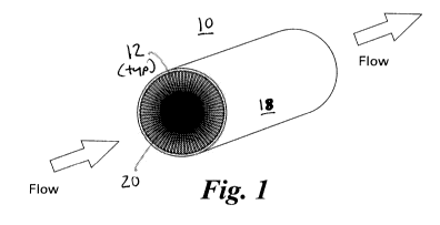
cylindrical column 10 defining fluid confining geometries configured as
segmented channels 12.
Segmented channels 12 are wedge-shaped so as to be wider across at a location
closer to the
outer surface 18 of the column than towards the central solid core 20 of the
column. Column 10
may be formed by extrusion of a suitable material using a caliber or stencil,
although other
methods conventional in the art are also contemplated. Desirably, solid
support resin loaded into
channels 12 defines a fluid passageway therethrough having a dimension that is
less than the
maximum range of a beta(+) or beta(-) range of a radioisotope to be conducted
therein or
therethrough. FIG. 2 illustrates an cylindrical column 30 defining a series of
elongate
passageways 32 extending therethrough. The passageways 32 provide confining
geometries with
characteristic inner dimensions that have at least one characteristic
dimensions below the beta+ /
beta- range of radioisotopes in use therewith. It is contemplated by the
present invention that the
resin could be provided by injecting into channels 14 a polymer emulsion which
is subsequently
cured (eg, by ultraviolet radiation) to form a polymer resin within channels
14.
[0038] In still another, embodiments, the filter device may be a wrapped
cylindrical column 50,
as shown in FIG. 3, formed from an elongate elastomeric sheet 52 rolled about
an elongate axis
54 such that the channel dimensions are related to the spacing between the
layers for each
convolution. The fluid confining geometry is thus defined between overlying
faces of sheet 52
with a spacing means 56 extending therebetween. In certain other embodiments
the fluid
confining geometry maybe a sponge-like or porous substrate 58 wrapped along
sheet 52 so as to
8
CA 02840495 2013-12-24
WO 2013/003530
PCT/US2012/044527
provide open inner channels, chambers, conduits or fluid confinements along
column 50 with a
characteristic dimension below the beta+/beta- range of radioisotopes in use.
Additionally,
porous substrate 56 is also contemplated to provide a functional surface
coating allowing
purification and/or concentration of radiopharmaceutical compounds or
radioisotopes.
Alternatively still, instead of a porous substrate, the present invention
contemplates that column
50 may include elongate longitudinal spacers extending the length of column 50
so as to define a
plurality of elongate passageways extending therethrough. Each passageway may
further include
a solid support resin such that each passageway includes a dimension below the
beta+ / beta-
range of radioisotopes in use therewith. In each embodiment, the passageways
or channels
provide an opening at each end of column 50 and in fluid communication with
each other
through the column. In accordance with the present invention, the fluid
confining geometry of
has to have a dimension smaller than the positron interaction range. Thus in
the case of a UV-
cured sponge the resin itself may provide passageways smaller than the
positron interaction
range and hence be the fluid confining element. Alternatively, where a channel
is filled with
beads, the channel should be smaller than the positron interaction range and
the beads even much
smaller so that the channel includes a dimension smaller than the positron
interaction range.
[0039] In each embodiment, the filtration device may comprise a functional
surface coating or
solid support for purification, phase transfer, concentration of the
radioisotope or
radiopharmaceutical compound, or combinations thereof. The functional surface
coating and
solid state resin are those generally used in separation/purification systems,
including but not
limited to, QMA, SEP-Paks, SPE cartridges, LC, HPLC, and TLC.
[0040] The solid support may be any suitable solid-phase support which is
insoluble in any
solvents to be used in the method but to which selective component of the
filtrate solution may
be bound. Examples of suitable solid support include polymers such as
polystyrene (which may
be block grafted, for example with polyethylene glycol), polyacrylamide, or
polypropylene, or
glass or silicon coated with such a polymer. The solid support may take the
form of small
discrete particles such as beads or pins, or as coatings on a particle, for
example, of glass or
silicon, or a coating on the inner surface of a cartridge or microfabricated
device such as one or
multiple microfluidic channels.
9
CA 02840495 2013-12-24
WO 2013/003530
PCT/US2012/044527
[0041] For example, [18F] -fluoride (fluorine-18) is useful for
preparation of
radiopharmaceuticals by nucleophilic fluorination, specifically for use in
Positron Emission
Tomography (PET).
[0042] Fluorine-18 is obtained by a variety of nuclear reactions from both
particle accelerators
and nuclear reactors, and can be produced at specific activities approaching
1.71 x10⁹ Ci/mmol.
The half-life of fluorine-18 is 109.7 minutes, relatively long in comparison
with other commonly
used radioisotopes but still imposing time constraints on processes for
preparing 18F-labelled
radiopharmaceuticals.
[0043] Fluorine-18 may be produced by irradiation of an [180]oxygen gas target
by the nuclear
reaction 180(p,n)18F, and isolated as [18F]fluoride ion in aqueous solution.
It also may be
produced by exposing the target to H2180 and irradiating. In aqueous form,
[18F]fluoride can be
relatively unreactive, and so certain steps are routinely performed to provide
a reactive
nucleophilic [18F]fluoride reagent. Following irradiation, a positively
charged counterion is
added, most commonly potassium complexed by a cryptand such as Kryptofix 222
(4,7,13,16,
21,24-hexaoxa-1, 10-diazabicyclo [8,8,8] hexacosan), or alternatively, cesium,
rubidium, or a
tetralkylammonium salt. This is commonly achieved by passing the [18F]
fluoride target water
(typically in volumes of 1 to 5mL) through an anion exchange resin and eluting
with a slightly
aqueous organic solution (typically in a volume of 0.1 to 5mL) of the
counterion, for example,
with a potassium carbonate/Kryptofix solution in water/acetonitrile. Secondly,
the solution is
dried, commonly by azeotroping in the presence of a low- boiling solvent such
as acetonitrile.
[0044] Automated radiosynthesis apparatus routinely include such a drying
step, typically
lasting 9 minutes in the case of [18F]FDG synthesis on Tracerlab MX (GE
Healthcare). The
compound to be labeled (dissolved in an organic solvent suitable for
performing the subsequent
radiosynthesis, usually an aprotic solvent such as acetonitrile,
dimethylsulphoxide or
dimethylformamide) is then added to the dried residue of [18F]fluoride and
counterion.
[0045] By using a filtration device as described above, filtration through the
device may allow
rapid, trapping and elution of [18F]fluoride from target water using a solid
support system.
Exemplary materials are described in WO 2009/083530, incorporated herein by
reference.
CA 02840495 2013-12-24
WO 2013/003530
PCT/US2012/044527
[0046] Purification, phase transfer and or concentrating of a radioisotope may
be executed in
serial manner or via parallel capillary channels. The channels comprise a
proximal end and a
distal end to allow fluid movement. In other embodiments, the channel may
comprise a single
opening wherein fluid transfer into and out of the vessel occurs through the
same opening.
Dimensions are dependent on the emitted beta+/beta- energy of the utilized
radioisotope during
decay and the resulting maximum beta+/beta- range. For example, for 18F, the
maximum range
for the positrons emitted in water is 2.3mm. Therefore embodiments for the
purification, reactor
or storage vessel may comprise fluid confining geometric arrangements with a
characteristic size
below 2.3 mm for use with 18F.
[0047] In other embodiments the fluid confining geometric structure maybe a
thin film or
surface coating along the channel with at least one characteristic dimension
below the beta+ /
beta- range of radioisotopes in use.
[0048] In certain embodiments, the characteristic dimensions of the fluid
confining geometric
structures for the filter device may be defined based on the specific
beta+/beta- emitters in use.
This is shown but not limited to the values displayed in Table 1, which list
maximum and
average range of positrons in water for several commonly used medical
isotopes. The present
invention contemplates that the channel (or confining geometry) should have a
dimension that is
smaller than the maximum range. More desirably the channel should have a
dimension that is
smaller than the average range. More desirably still the channel should have a
dimension of
about 10-15% of the maximum range.
11
CA 02840495 2013-12-24
WO 2013/003530
PCT/US2012/044527
Radionuclide Range in water [cm] Average range in
water
[cm]
C-11 0.39 0.103
C-14 0.028 0.013
N-13 0.51 0.132
0-15 0.8 0.201
F-18 0.23 0.064
P-32 0.785 0.198
Rb- 82 1.65 0.429
Table 1: Maximum and average range of positrons in water for common medical
isotopes
[0049] In certain embodiments the filtering device may have a channel width in
the range of
about 0.01 lam to 3000 lam and in another embodiment the channel depth may
range from about
1 lam to 2000 lam. It is understood that the channel cross-section may be
essentially cylindrical,
oval or rectangular in shape or combinations thereof. The length of the
channel is arbitrary in
that it is chosen based on required volume capacity or flow.
[0050] The channels may be positioned as to provide a high packaging density.
As such,
geometries of the filtering device may include capillaries and capillary-like
assemblies such as
cylindrical or cubic shapes as well as geometries with meander-shaped, planar
rectangular, coin-
shaped structures or combinations thereof.
12
CA 02840495 2013-12-24
WO 2013/003530
PCT/US2012/044527
[0051] . Referring now to FIG. 4, the present invention provides the
confinement geometry
taking the form of a meandering fluid path 110. Fluid path 110 may be formed
as a two-piece
device having a planar COC 6017-SO4 substrate body 112 which defines an
elongate flow
channel 114 opening on a first major surface 116 thereof. A planar cover piece
(not shown) can
then then be bonded to overlay most or all of flow channel 114 so as to
provide an enclosed fluid
path 110. Fluid path 110 extends between a first inlet end 118 and a second
outlet end 120.
Fluid path 110 is shaped to form a series of elongate linear segments (eg, 122
and 124) in fluid
communication with alternating bending segments (123 and 125). Flow channel
114 is typically
includes a square or rectangular cross-section such that one of the dimensions
of the cross-
section is less than the beta(+) or beta(-) range of a radioisotope to flow
therethrough. For
example, flow channel 114 may have a cross-sectional dimension of 500[tm x
500[tm where
elongate segments 122 and 124 have an edge-to-edge spacing of 250[tm
Alternatively, fluid path
110 may be formed by an elongate elastomeric cylindrical tubing of dimensions
having a
circular cross-section less than beta(+) or beta(-) range of a radioisotope to
flow therethrough
and laid in an undulating shape between its inlet and outlet ends. The present
invention further
contemplates that channel 114 may have a rectangular, triangular or circular
cross-section, or
combinations thereof. Moreover, the present invention contemplates that
channel 114 is
contemplated to provide a region where mixing or other reactions may take
place or where a
fluid product may be stored.
[0052] In designing for low space consumptions, positron emission and
interaction to adjacent
channels must be considered. For example, re-entering probabilities and
energies for positrons
emitted by 18-fluoride decay to adjacent channels has been calculated and
estimated to show a
small to negligible effect (Table 2). The results have been experimentally
validated utilizing a
shielded capillary setup (re-entering suppressed by appropriate shielding) and
an on-chip
meander structure (channel: 500[tm x 500p.m, 250[tm spacing, material: COC
6017-SO4,
illustrated in FIG. 4) with no measurable difference in results between the
two configurations as
shown graphically in FIG. 5. More specifically, as shown in FIG. 5, there is
no significant
difference in autoradiolysis between the two systems; hence the results
suggest that there is no
significant positron interaction between adjacent channels in a meander-shaped
device with the
present configuration.
13
CA 02840495 2013-12-24
WO 2013/003530
PCT/US2012/044527
Channel Channel Channel Channel Nr. of Rel. Total
width height Spacing Volume parallel Energy energy
[pm] [pm] [pm] [111] channels increase flux [%]
ro l
250 500 250 200 56 +1.4 34.5
250 250 150 200 88 +1.5 29.7
500 500 250 200 32 +1.3 49.0
250 250 250 200 80 +1.0 29.7
250 250 500 200 66 +0.4 29.1
750 750 500 200 17 +0.5 62.1
500 500 500 200 28 +0,.6 48.3
500 500 750 200 14 +0.2 47.9
Table 2: Interaction between adjacent geometric structures carrying
radioactive compounds on
the example of planar meander structures and [18F]FDG at 14.9 ¨ 23.1 GBq/m1
(FIG.1)
[0053] Even though impact of positron interaction between adjacent structures
has shown no
significant impact for 18-fluoride with activity concentrations between 4.3
and 23.1 GBq/ml, in
certain embodiments, shielding between adjacent fluid confining geometries may
be of interest
for beta+ / beta- radiation with higher energies than 18F or for activity
concentrations higher than
the evaluated amounts.
14
CA 02840495 2013-12-24
WO 2013/003530
PCT/US2012/044527
[0054] As such, in certain embodiments, the fluid confining geometry is
configured such that the
whole geometry or a given segment of the geometry is substantially isolated
from its nearest
neighbor geometry or neighbor segment such that no measurable kinetic positron
energy transfer
occurs between the fluid confining geometries or segments. Measurable positron
energy transfer
between channels refers to a shift in overall autoradiolysis suppression
towards decreased values
for decreasing channel spacing.
[0055] In certain embodiments a substrate material utilizing heavy materials
that lead to high
positron absorption and decrease the mean path length of positrons may be
used. Materials for
use in shielding includes usually solid or liquid materials of high density or
mass or both, such as
but not limited to lead, tungsten, epoxy and material combinations involving
elements that lead
to high beta+/beta- range damping or absorbance.
[0056] In certain embodiments shielding between adjacent fluid confining
geometric structures
may be achieved with absorbing material inserts between these structures
(inlets). In other
embodiments, design of adjacent or intermediate compensation structures such
as channels or
cavities filled with water or other fluids that lead to positron path length
reduction or scattering
may be used to reduce autoradiolysis induced between neighbor structures . The
same shielding
fluids may be utilized for heating and cooling of the structures that
carry/transport the radioactive
and non-radioactive reagents.
[0057] In certain embodiments, the purification device may be replaced by a
segmented flow
type arrangement for use with fluid volumes on the order of microliters to
picoliters. In such
embodiments, the outer dimensions of the respective droplets and the distance
between these
droplets define the characteristic dimensions for autoradiolysis reduction. In
certain other
embodiments, device is replaced by solid phase based surface chemistries.
Solid phase based
surface chemistries include, but is not limited to, chemistry on a frit or a
functional surface,
floating liquid films, interfacial chemistries and other assemblies wherein a
thin layer of the
radioactive compound may be included. In such embodiments the thin film shows
characteristic
dimensions below the beta+/beta- interaction range which leads to
autoradiolysis reduction.
[0058] In certain embodiments, the filtration device may be used for the
purification or
concentration of radiopharmaceuticals. The method may comprise adding a
mixture of a
CA 02840495 2013-12-24
WO 2013/003530
PCT/US2012/044527
radioisotope containing compound, such as a radiotracer and a pharmaceutical
carrier, to the
filtration device. The mixture would be added and allowed to flow through the
channels of the
filtration device and collected. The filtration device would be designed such
that the volume of
the channel is controlled to provide adequate residence or flow through time
through the filtering
system. The radioisotope containing compound may be a compound containing
radioisotopes
m 89
such as 18 11 14 99 F, C, C, Tc 123, I 125, I131, I 68 67
15, Ga, Ga, 0 13 82 62 32, N, Rb, Cu, P, Sr, 153 Sm, 186Re,
201T1, Win,
or combinations thereof. Preferred isotopes include those used for PET such as
18F,
11C and 68Ga.
[0059] The pharmaceutical carrier refers to a composition which allows the
application of the
agent material to the site of the application, surrounding tissues, or
prepared tissue section to
allow the agent to have an effective residence time for specific binding to
the target or to provide
a convenient manner of release. The carrier may include a diluent, solvent or
an agent to
increase the effectiveness of the radiopharmaceutical produced. As such the
carrier may also
allow for pH adjustments, salt formation, formation of ionizable compounds,
use of co-solvents,
complexation, surfactants and micelles, emulsions and micro-emulsions. The
pharmaceutical
carrier may include, but is not limited to, a solubilizer including water,
detergent, buffer solution,
stabilizers, and preservatives.
[0060] The invention may enable synthesis to occur at an increased activity
and high reagent
concentration levels by appropriate design of respective channel assemblies.
Issues of radiotracer
synthesis at high activity levels have been reported with comparably low yield
[Santiago J. et al:
Reactor scale effects on F-18 Radiolabeling; 18th ISRS, Edmonton, Canada, July
12-17 2009,
Poster]. With an appropriate system design utilizing geometric structures as
described may
improve yield due to decrease in autoradiolysis. In certain embodiments the
improvement may
be obtained during synthesis including for example but not limited to
radiolabeling, hydrolysis,
purification (e.g. SEP Pack or QMA cartridge), reformulation and
concentration.
[0061] In certain embodiments, the device may be used for reduction of
autoradiolysis in
radioisotope containing compounds productions, including for example
radiotracer production
and autoradiolysis which may be especially present during purification of the
target compound.
Usually, QMA, SEP-Paks, SPE cartridges, LC, HPLC, and TLC methods are utilized
for
16
CA 02840495 2013-12-24
WO 2013/003530
PCT/US2012/044527
cleaning, purification and separation. The solid state resins used in such
methods create a high
local concentration of radioactive material, leading to high radiolysis. By
specifying the
geometric design of the device, autoradiolysis can be reduced. This applies
for conventionally
packed cartridges and columns using geometric confining element having
dimensions below the
beta+ / beta- range of radioisotopes in use.
[0062] In certain embodiments, the filtration device may be structures and
capillaries on-chip or
off-chip or inside a bulk material containing functional surface coatings or
resins for purification,
phase transfer and concentration of radioisotope containing material such as,
but not limited to
radiopharmaceuticals.
[0063] Autoradiolysis which is created by interaction of radicals may also be
reduced by surface
modifications to getter radicals that lead to a permanent or temporary
capturing/binding of
radicals to a surface. Due to short diffusion lengths for particles in micro-
channels, the
probability of a radical reaching the wall a capillary tube or a microfluidic
structure before
interacting with a radiolabeled molecule of interest is higher than compared
to a conventional
vessel.
[0064] In certain embodiments, the device may further comprise a device for
collecting and
transferring the radioisotopes. For example, the device may be designed such
that in in fluid
communication with another element, that can be used for transferring or
storing the
radioisotopes prior to its end use. In certain embodiments, the device may be
part of an assembly
which is loaded and unloaded utilizing high gas or fluid pressure,
MODELING STUDIES
[0065] 18F decays in 97% of cases to 180 via -" and ye emission and in 3% of
cases via electron
capture (Cherry S, Sorenson J, Phelps M, Physics in Nuclear Medicine, Saunders
(2003)).
During a -" decay event, a proton decays into a neutron, a positron, and a
neutrino, with the
difference between the binding energy and the energy converted into mass,
shared between the
kinetic energy of the positron and the neutrino and, less often, a photon.
Neutrinos interfere only
very weakly with surrounding matter, and it is reasonable to ignore their
effects in the
autoradiolysis process, just as it is justifiable to neglect the statistically
less likely decay process
17
CA 02840495 2013-12-24
WO 2013/003530
PCT/US2012/044527
of 18F electron capture. In contrast, a positron of high energy is relevant as
it can directly lead to
a chain of ionization events in the process of dissipating its kinetic energy.
[0066] An intact [18F]FDG molecule can lose the 18F atom if it is ionized
directly by a positron
or hit by a radical that causes charge transfer between the two particles. At
activity
concentrations of <20 GBq/m1 [18F]FDG in water, the probability of a positron
ionizing intact
[18F]FDG molecules directly is estimated as <1% based on molar concentrations
of active
compounds versus water molecules. For this reason, the dominant mechanism for
autoradiolysis
is the interaction of radical species with intact [18F]FDG molecules. Buriova
et al. have reported
that the post-autoradiolytic HPLC-MS and TLC analysis showed that OH and 02
are the two
species that are most likely to cause 18F release (Buriova E. et al., Journal
of Radioanalytical and
Nuclear Chemistry, Vol 264 No 3 (2005) 595-602). Such reactions, if occurring
with enough
kinetic energy, lead to electron exchange and subsequent breaking of e.g. 18F
bonds. Hence,
autoradiolysis can be characterized based on the radiochemical purity (RCP) of
a radiotracer
solution which is determined by measurements of free 18F versus intact
[18F]FDG molecules
utilizing thin layer chromatography (TLC) or high pressure liquid
chromatography (HPLC)
coupled with a radiation detector (radio-HPLC).
[0067] The energy spectrum of the 18F decay has been studied and the kinetic
energies of the
positron have been determined to be
EMI= = 0,633 AleV and a mean energy
0,211 MeV. After the release of the positron, its kinetic energy is dissipated
via ionization, inelastic excitation, and positronium formation which after
annihilation
subsequently leads to the release of two ") photons, each with an energy of E-
511 ke . The
distance in water where 90% of this radiation is deposited is approximately
24cm which is
much larger than the discussed geometries for the device design <2cm. Thus,
the contribution of
511keV ") radiation to ionization can be neglected in the autoradiolysis
model. Furthermore, for
positrons with kinetic energies of the 18F decay spectrum the energy losses
due to radiation
processes are negligible (Cherry S, Sorenson J, Phelps M, Physics in Nuclear
Medicine,
Saunders (2003)).
[0068] The energy transferred to the 180 daughter nucleus due to momentum
conservation after a
positron release, including relativistic considerations, has a maximum of
approximately 31 eV
18
CA 02840495 2013-12-24
WO 2013/003530
PCT/US2012/044527
since the mass ratio of a positron to an 180 atom is ¨105. Lapp and Andrews
reported the mean
ionization energy for water as 68 eV and the lowest ionization energy as 11.8
eV (Lapp,
Andrews, Nuclear Radiation Physics, Prentice Hall, 1972, p. 154). This means
that the recoil
effect of positron emission on the daughter nucleus with max. 31 eV has
negligible effect on
autoradiolysis when compared to the direct effect of the positron which has an
average energy in
the range of 230000 eV.
[0069] It is assumed that the fraction H(r) of the total energy lost by the
positron each time it
collides and ionizes is approximately constant for all distances r from the
daughter nucleus.
Furthermore, it is assumed that the number of ions produced is proportional to
the energy lost as
ionization energy, and that the number of 18F atoms released correlates
linearly on the number of
positron-generated radicals in solution. Ionization energy is hereby defined
as the energy that is
lost by a positron during ionization of an atom. In general, not all the
positron energy is lost to
overcome the binding energy of an electron but it may also be lost in
secondary processes such
as photon emission or as kinetic energy transferred to the emitted electron.
[0070] The model developed for the estimation of autoradiolysis effects in
small geometries is
based upon energy conservation considerations and represents the worst case
scenario. This
means that due to the assumptions made in (2.) the measured autoradiolysis
should not exceed
the values predicted by the model. All calculations refer to 18F decay and the
corresponding
positron energy levels.
[0071] When the number of ions Afton,. produced is proportional to the
deposited ionization
energy, then N,õ,,,s can be calculated as:
Nions(r)x H (r) = Flobsorb(r), (1)
where 11 (r ) is the fraction of energy lost due to ionization for a constant
distance r and Eabsorb(r)
is the total energy deposited up to distance r. The results of Palmer and
Brownell have been used
for the estimation of the fraction of total deposited energy in the system
(Palmer and Brownell,
1992 IEEE Trans. Med. Imaging 11, 373-8). Palmer et al. have reported that the
3D distributions
of the positron annihilation events can be interpolated by the Gaussian
function
19
CA 02840495 2013-12-24
WO 2013/003530
PCT/US2012/044527
(
eXP r.2 )2). (2)
P(r) ........................ _2C-1-QA
a v2
[0072] Parameters 1.0 and a, obtained by Gaussian fittings, have been reported
for different
isotopes. In order for P(r) to be the probability density, the normalization
function (I) is
introduced and defined as:
e-x2dx. (3)
o
[0073] It has been shown by Champion et al. that for 18F decay ro = 0,04 mm
and
= 0,789 Tnnz for water as the decay event surrounding medium (Champion C, Le
Loirec C,
Phys.Med.Biol. 52 (2007), 6605-6625). Using these fit parameters the
cumulative positron
annihilation probability curve, defined as
T(x) =
P(r)tir, (4)
o
is shown in FIG.6. This curve yields the probability that a positron from the
18F spectrum
annihilates up to a certain distance x.
[0074] FIG. 6 suggests that approximately 80% of positrons annihilate after
passing through a 1
mm thick layer of water. This result corresponds well with Monte Carlo
simulation values
reported by Champion et al. (76%) and Alessio et al. (79%) (Champion C, Le
Loirec C,
Phys.Med.Biol. 52 (2007), 6605-6625 and Alessio A., MacDonald L., Nuclear
Symposium
Conference Record, 2008)).
[0075] The range-energy relations for positrons and electrons have been
broadly studied and the
results from Katz and Penfold demonstrate that there is an empirical relation
between the energy
and the range (Katz L, Penfold A.S, Rev.Mod. Phys. 24, 28 (1952)).
[0076] For the transmission of a mono-energetic 13 particle beam in aluminum
with an energy
Eu, where O. 01 MeV < < 2, 5 MeV, the following empirical relation has
been postulated:
CA 02840495 2013-12-24
WO 2013/003530
PCT/US2012/044527
Mg) = 412 . En.,265-0, 954in(r), (5)
where the range R(E) is expressed in (ingicin2) whereas E' is dimensionless,
given by
Ei =.1*. Using this relationship, the range in a specific matter can be
calculated by dividing
the range R(E' ) by the density of the matter:
Ng
Range(E1 = ) . (6)
P
[0077] The empirical energy-range relation (5) can transform the cumulative
annihilation
probability distribution T(x) in (4), into a function that shows the fraction
of total energy
deposited Eabsorb(r) up to the distance r from the daughter nucleus. In a more
general form:
E(r) = T(r) = Range '(r), (7)
r
where T(r) -------- f P(u)du is the annihilation probability and Rzinge-1
denotes the inverse
a
function of Range(E).
[0078] A rigorous derivation of equation (7) should consider backscattering,
however, the work
of Kobetich and Katz justify that backscattering can be neglected in this case
(Kobetich R., Katz
L., Physical Review, Vol 170 No 2, 1968).
[0079] The normalized dissipation energy curve for positrons in water based on
(7) is shown in
FIG. 7. Water is chosen as the medium since injectable radiopharmaceuticals
are usually
aqueous solutions.
[0080] It can be seen from the FIG. 7that about 85% of the positrons kinetic
energy is deposited
in the first 1 mm of the surrounding water and only 13% within the first
100p.m. Following the
assumption that the autoradiolysis phenomena is linearly proportional to the
number of ions in
solution, and that the number of ions created is proportional to the amount of
energy deposited in
the system as ionization energy Eabsorb(r) (see 2.), the results suggest that
autoradiolysis effects
can be reduced to approximately 30% by tailoring the geometry to Arth = 250
Am. This means
21
CA 02840495 2013-12-24
WO 2013/003530
PCT/US2012/044527
a reduction by 70% in comparison to conventional geometries where the mean
path length is
approximately equal to the positron's range Apah P.1 I? with R = 2.3mm for
18F.
APPLICATION TO CYLINDRICAL AND PLANAR SYSTEMS
[0081] A general cylindrical system suitable for analysis with the previously
developed model is
described by a cylinder with length L and radius r, such that L >> r. This
approximation allows
end-effects to be neglected. A further constraint for model applicability is
that the cylinder is
shielded or otherwise configured in a way such that a positron leaving the
cylinder cannot reenter
at another location.
[0082] The mean path length may be defined as the average distance of a
positron traveling
inside a given configuration of geometric boundaries such as a cylinder or a
planar structure,
taking multiple starting positions and directions in a three dimensional
geometry into account.
The mean path length correlates with the energy dissipated inside a geometric
configuration.
Hence, the mean path length represents the link between the autoradiolysis
model of positron
energy dissipation (FIG. 4) and the actual geometric configuration explored.
[0083] To calculate the mean path length as a function of the cylinder's
radius for positrons
emitted during 18F decay and their respective energy distribution and range, a
Monte Carlo
simulation was executed with 100,000 positrons for each cylinder radius
varying between 0 to
2.3mm. The result of the simulation is displayed in FIG. 8
[0084] Referring now to FIG. 9, the present invention also provides a reactor
210 formed
between two thin sheets.(not shown). Reactor 210 is contemplated to provide a
region where
mixing or other reactions may take place or where a fluid product may be
stored. The sheets are
separated by a spacer 212 and 214 bonded thereto and which define a reaction
chamber 216
extending between an inlet 218 and an outlet 220. Reaction chamber 216, inlet
218 and outlet
220 are thus enclosed by the two sheets between which spacers 212 and 214
extend, such that
inlet 218 and outlet 220 are placeable in fluid communication with a fluid
network (not shown).
For reference, as shown in FIG. 9, a being the length, b the width and c the
distance between the
bottom and top sheets of the reactor 210, such that a >> c, b>> c, and c is
desirably less than
the maximum beta(+) or beta(-) range of a radioisotope flowed into reaction
chamber 216. The
22
CA 02840495 2013-12-24
WO 2013/003530
PCT/US2012/044527
mean path for reactor 210 was also examined utilizing a Monte Carlo
simulation. For each
distance between the sheets, the simulation has been run with 100,000
positrons and the results
are displayed in FIG. 8. Circular embodiments instead of the present
rectangular example are
expected to show similar results for energy deposition and resulting
autoradiolysis.
[0085] With the positron mean path lengths for the cylindrical (FIG.8) and
planar (FIG. 10)
configurations determined, the fraction of kinetic positron energy deposited
into a fluid inside
these geometric configurations can be calculated according to (7).
Characteristic dimensions are
the radius r for the cylinder and the thickness c for the planar geometry. The
results are displayed
in FIG.8. The maximum characteristic dimension where Eabsorb=100% was set to
r=c=2.7mm for
both configurations.
[0086] The results show that both geometric arrangements can be used for
autoradiolysis
reduction, if the characteristic dimensions are chosen small enough. With the
assumption of
Nions rX E absorb the results in FIG. 11 suggest that a cylindrical capillary
with radius
= 250 /Ho results in a comparative level of autoradiolysis not exceeding 36%
of that found in
the bulk device configuration (eg, when held in bulk in a standard laboratory
vial having a vial
cavity diameter of 3mm or greater) with the bulk vial cavity having an
interior radius of 2.7mm.
Furthermore it can be concluded that cylindrical-like systems offer a higher
potential for
autoradiolysis reduction than planar shapes. In contrast, planar structures
offer an increased
packaging density and lower absolute internal surface area, both being
potentially important
parameters during system design.
[0087] The model assumes that a positron loses a constant fraction of its
instantaneous kinetic
energy due to ionization, independent of the distance to the decaying atom.
Upon first inspection,
this approximation seems to be bold, since the total ionization cross-section
for positrons in
water is a complex function of the kinetic energy. The claim can be justified
by considering not
23
CA 02840495 2013-12-24
WO 2013/003530
PCT/US2012/044527
EXPERIMENTAL
Materials & Methods:
[0088] The autoradiolysis trends predicted by the theoretical model were
evaluated
experimentally by synthesizing non-stabilized [18F]FDG and distributing the
product into a
variety of geometries. A GE TRACERlab MX synthesizer (GE Healthcare, Liege,
Belgium)
together with TRACERlab MXFDG cassettes (Cat.No: PS150ME, GE), the [18F]FDG
reagents kit
(Prod.No.: K-105TM, ABX, Radeberg, Germany) and Mannose Triflate plus
(Prod.No.:
107.0025, ABX) were utilized for synthesis. A GE PETtrace cyclotron (GE
Healthcare, Uppsala,
Sweden) was used to irradiate two silver targets with 1.6 ml of H2180 each
(dual beam mode) for
up to 90 minutes at 35 [IA for each target to generate 18F-activity of up to
ca. 200 GBq. The
standard [18F]FDG synthesis protocol and cassette was modified to avoid
introduction of ethanol
into the process (ethanol vial in cassette replaced by empty flask). Prior to
synthesis, two C18-
cartrigdes were removed from the cassette and manually conditioned with 10 ml
of ethanol, 20
ml of water, dried with air and subsequently reassembled into the cassette. A
total number of ten
syntheses were performed, each producing 4 ml of [18F]FDG at activity
concentrations between 4
GBq/m1 and 23 GBq/ml. No ascorbic acid, ethanol nor other stabilizers were
added prior, during
or after synthesis. The synthesis output was examined for residual ethanol by
GC-MS (6890N
Network GC-System with MS 5975B, Agilent Technologies, Germany).
[0089] The synthesis product was then distributed using an automated
experimental set-up as
shown in FIG. 12. A bulk collection vial 310 was provided to receive 4mL at 4-
23GBq/m1 of
non-stabilized [18F]FDG dispensed from a GE TRACERLab MX (sold by GE
Healthcare, Liege,
BE). The contents were then directed (through conduits not shown) from vial
310 through a PC-
controlled syringe pump 312 with a 10-port distribution valve to a variety of
receiving
containers. A first receiving vial 330 containing 15% ethanol in water
solution was provided for
initially receiving 300 pi [18F]FDG as a start reference. Also provided were a
first, second, and
third length of PEEK capillary tubes 340, 350, and 360, respectively.
Capillary tubes 340, 350,
and 360 had outer diameters of 1/16" and inner diameters (ie, containment
geometries) of 250 p.m,
500p.m, and 750 p.m, respectively. The capillary length was varied to keep a
constant internal
24
CA 02840495 2013-12-24
WO 2013/003530
PCT/US2012/044527
volume of 200 pl. The capillaries were wrapped around a steel core of 15 mm
diameter, in a
spiral with a helical pitch of 4 mm. The spiral wrapped capillaries were
shielded by 3 mm of
aluminum. The shielded spiral configuration ensured that positrons leaving the
capillary had no
opportunity to re-enter a segment of the adjacent capillary. 200 pi of
[18F]FDG was injected from
bulk vial 310 into each capillary 340, 350, and 360. Additionally a 2m1 glass
vial 370 was
provided to receive a sample of [18F]FDG at the time of dispensing into
capillary tubes 340, 350
and 360. Lastly, a second receiving vial 380 containing 15% ethanol in water
solution was
provided for initially receiving 300 pi [18F]FDG as a stop reference.
[0090] Autoradiolysis suppression was defined as the reduction in
autoradiolysis relative to a
300 1 sample stored in a bulk reactor. The bulk reactor result was created
from storage of non-
stabilized [18F]FDG in the 2m1 glass vial 370 which was part of the capillary
filling routine. The
results observed in a bulk reactor may be correlated to residence time within
a microfluidic
filtration device compared to a bulk filtration device.
[0091] The capillary filling routine also included a first step and a last
step where 300 1 of
[18F]FDG was dispensed into vials 310 and 380 with 15% ethanol solution
present. These two
samples were taken in order to evaluate the impact of the capillary filling
time (about 20min to
30min) on the final autoradiolysis result after 14 hours, since the
autoradiolysis rate is at its
maximum directly after synthesis [see Fawdry, R.M., 2007, Radiolysis of
2418F]fluoro-2-
deoxy-o-glucose (FDG) and the role of reductant stabilisers. App. Radiat.
Isot. 65(11), 1192-
1201; Scott et al., 2009, J. Appl. Radiat. Isot. 67 (1), 88-94].
[0092] After 14 hours, the contents of capillary tubes 340, 350, and 360 were
ejected into
separate vials utilizing H20 and subsequently the ratio of free 18F to
[18F]FDG in each capillary
output solution and all bulk vial standards was determined. TLC (Polygram SIL
G/UV 254;
Macherey-Nagel) and an autoradiograph (Phosphor-Imager Cyclone Plus,
PerkinElmer,
Germany) were used to quantify the ratio of free 18F to [18F]FDG which also
known as
radiochemical purity (RCP).
CA 02840495 2013-12-24
WO 2013/003530
PCT/US2012/044527
Results:
[0093] The autoradiolysis suppression for all experiments is summarized in
FIG.13. It was
calculated for all runs from the respective RCP of the 300 1 glass vial
reference sample (worst
case, 0% autoradiolysis suppression after 14 hours) to the initial RCP after
synthesis (best case,
minimum autoradiolysis). FIG. 13 shows that an ID 250 p.m capillary provides
an autoradiolysis
suppression of >90% whereas an increasing capillary diameter results in a
reduction of the
suppression factor which is in general agreement with the trend predicted by
the model.
[0094] The ethanol content was measured to <2 mg/1 ethanol for all experiments
(detection limit
of the instrument). The difference in autoradiolysis between the 300 1 ethanol
stabilized samples
taken prior and after capillary filling was measured <1%, suggesting that the
filling time had no
impact on the final results.
[0095] FIG. 14 displays experimental results for the autoradiolysis
suppression inside an ID 250
p.m capillary (n=9) versus the respective activity concentration for each run.
There are no
significant trends suggesting that the results displayed in FIG. 14 are
comparable for the activity
concentrations chosen.
[0096] Apart from activity concentration, the results of FIG. 14 may have been
affected by
permanent immobilization of free 18F on the inner capillary surface. In order
to investigate this
aspect for the present configuration of tubing and materials, the capillaries
were flushed with
400 1 of water after each experimental run and the rinses were analyzed by
TLC. Water has
shown to be very effective for cleaning residual activities from capillary
tubing. The results
yielded similar ratios of 18F to [18F]FDG as the original capillary contents
(variation of +/- 3%)
and provided no evidence for the capillary acting as a 18F trap. However,
temporary surface
immobilization effects for 18F as well as permanent or temporary
immobilization of free radicals
may have an effect and cause the discrepancy between the model (linear
correlation with
capillary diameter) and experimental results (non-linear correlation with
capillary diameter).
According to the theoretical results of the cylinder, planar devices with
appropriate dimensions
would show comparable results.
26
CA 02840495 2013-12-24
WO 2013/003530
PCT/US2012/044527
[0097] While only certain features of the invention have been illustrated and
described herein,
many modifications and changes will occur to those skilled in the art. It is,
therefore, to be
understood that the appended claims are intended to cover all such
modifications and changes as
falling within the true spirit of the invention.
27