Note: Descriptions are shown in the official language in which they were submitted.
1
Crossbow Cabling Arrangement
BACKGROUND OF THE INVENTION
This invention relates generally to crossbows and more particularly to a
cabling arrangement that provides for more balanced forces.
Crossbows are generally known in the art. Crossbows typically include a
bow assembly portion mounted on a stock portion, which typically includes a
string
latch and trigger assembly for holding a drawn crossbow string and selectively
releasing
it.
When a bow portion comprises a compound bow, often multiple cables
are held away from the shooting axis by a portion of the stock. There remains
a need for
cabling arrangements that provide for a more balanced crossbow system.
Without limiting the scope of the invention a brief summary of some of
the claimed embodiments of the invention is set forth below. Additional
details of the
summarized embodiments of the invention and/or additional embodiments of the
invention may be found in the Detailed Description of the Invention below.
A brief abstract of the technical disclosure in the specification is
provided as well. The abstract is not intended to be used for interpreting the
scope of
the claims.
BRIEF SUMMARY OF THE INVENTION
In at least one embodiment, a crossbow comprises a stock, a first limb, a
first rotatable member, a second limb and a second rotatable member. A
bowstring and
a first cable each extend between the first rotatable member and the second
rotatable
member. The crossbow defines a shooting axis, and the stock extends below the
shooting axis. The first cable is positioned above the shooting axis. In some
embodiments, a crossbow comprises a cable positioner arranged to position the
first
cable. In some embodiments, the cable positioner comprises a roller.
CA 2840629 2019-06-21
CA 02840629 2014-01-23
2
In at least one embodiment, a crossbow comprises a stock, a first limb, a
first rotatable member, a second limb and a second rotatable member. A
bowstring, a
first cable and a second cable each extend between the first rotatable member
and the
second rotatable member. The crossbow defines a shooting axis. The first cable
is
offset from the shooting axis in a first direction and the second cable is
offset from the
shooting axis in a second direction different from the first direction.
In some embodiments, the first cable is positioned above the shooting
axis and the second cable is positioned below the shooting axis.
In some embodiments, a crossbow comprises a stock, a first limb, a first
rotatable member, a second limb and a second rotatable member. A bowstring, a
first
cable and a second cable each extend between the first rotatable member and
the second
rotatable member. The crossbow defines a shooting axis. A cable guard
comprises a
first cable positioner and a second cable positioner. The first cable
positioner is
arranged to hold the first cable above the shooting axis, and the second cable
positioner
is arranged to hold the second cable below the shooting axis.
These and other embodiments which characterize the invention are
pointed out with particularity in the claims annexed hereto and forming a part
hereof.
However, for a better understanding of the invention, its advantages and
objectives
obtained by its use, reference can be made to the drawings which form a
further part
hereof and the accompanying descriptive matter, in which there are illustrated
and
described various embodiments of the invention.
BRIEF DESCRIPTION OF THE DRAWINGS
A detailed description of the invention is hereafter described with
specific reference being made to the drawings.
Figure 1 shows an embodiment of a crossbow in a brace orientation.
Figure 2 shows a portion of a crossbow in greater detail.
Figure 3 shows the crossbow of Figure 1 in a drawn orientation.
Figure 4 shows a top view of an embodiment of a crossbow in a brace
orientation.
Figure 5 shows a top view of the crossbow of Figure 4 in a drawn
orientation.
CA 02840629 2014-01-23
3
Figure 6 shows another embodiment of a crossbow.
Figure 7 shows another view of the cable positioning members shown in
Figure 6.
Figure 8 shows a top view of the cable positioning members of Figures 6
and 7.
Figure 9 shows the crossbow of Figure 6 in a drawn orientation.
Figure 10 shows another embodiment of a crossbow in a brace
orientation.
Figure 11 shows the crossbow of Figure 10 in a drawn orientation.
DETAILED DESCRIPTION OF THE INVENTION
While this invention may be embodied in many different forms, there are
described in detail herein specific embodiments of the invention. This
description is an
exemplification of the principles of the invention and is not intended to
limit the
invention to the particular embodiments illustrated.
For the purposes of this disclosure, like reference numerals in the figures
shall refer to like features unless otherwise indicated.
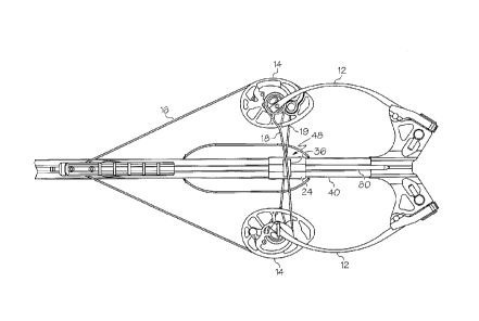
Figure 1 shows an embodiment of a crossbow 10 in an undrawn or brace
condition. In some embodiments, a crossbow 10 comprises a compound bow portion
20
and a stock portion 40. The bow portion 20 comprises limbs 12, rotatable
members 14
and a bowstring 16. The bow portion 20 further comprises a first cable 18 and
a second
cable 19 that extend between the rotatable members 14. As the crossbow 10 is
drawn,
the limbs 12 flex and change shape, resulting in movement of the cables 18,
19.
In some embodiments, the bow portion 20 comprises a dual cam bow
wherein both rotatable members 14 comprise cams, and cables 18, 19 each
comprise a
power cable. In some embodiments, the rotatable members 14 and cables 20 are
mirrored across a shooting axis 34, desirably providing a system that is
substantially
laterally balanced.
An arrow or bolt 80 desirably travels along the shooting axis 34 when
launched. In some embodiments, the stock 40 extends below said shooting axis
34.
Desirably, the cables 18, 19 are held away from the shooting axis 34,
which allows clearance for a bolt 80. Desirably, the first cable 18 is
positioned away
= CA 02840629 2014-01-23
4
from the shooting axis 34 in a first direction, and the second cable is
positioned away
from the shooting axis 34 in a second direction that is different from the
first direction.
In some embodiments, the first direction is opposite the second direction. In
some
embodiments, the first cable 18 is positioned above the shooting axis 34 and
the second
cable is positioned below the shooting axis 34. This arrangement helps to
balance
forces in the crossbow 10, for example reducing rotatable member 14 lean when
compared to a crossbow that routes multiple cables on a common side of the
shooting
axis 34.
In some embodiments, the crossbow 10 comprises a first cable positioner
48 arranged to position the first cable 18. In some embodiments, the crossbow
10
comprises a second cable positioner 50 arranged to position the second cable
19.
Figure 2 shows embodiments of a first cable positioner 48 and a second
cable positioner 50 in greater detail.
In some embodiments, the first cable positioner 48 comprises a body 24
that is arranged to position the first cable 18 away from the shooting axis
34. As shown
in Figure 2, the body 24 is attached to the stock 40. In some embodiments, the
body 24
can be formed integrally with the stock. In some embodiments, the body 24
comprises
opposed sidewalls 26 and a top 25. In some embodiments, the body defines a
tunnel
through which a bolt 80 passes during launch. Desirably, the tunnel is sized
to
accommodate vanes or fletching of the bolt 80.
In some embodiments, the first cable positioner 48 comprises a recess or
channel 49, and the first cable 18 is positioned in the channel 49. In some
embodiments, the channel 49 is formed in the body 24. A channel 49 can have
any
suitable orientation and is desirably oriented to match the first cable 18.
For example,
the first cable 18 will generally cross the shooting axis 34 at a non-zero
angle (e.g. when
viewed from above). In some embodiments, a longitudinal axis of the channel 49
is
oriented at an angle to the shooting axis 34, similar to an angle of the first
cable 18. It
should be noted that the crossing angle of the first cable 18 can be different
in the brace
and drawn conditions. In some embodiments, a longitudinal axis of the channel
49 is
oriented to match the crossing angle of the first cable 18 in the brace
condition. In some
embodiments, a longitudinal axis of the channel 49 is oriented to match the
crossing
angle of the first cable 18 in the drawn condition. In some embodiments, a
longitudinal
CA 02840629 2014-01-23
axis of the channel 49 is oriented to match an average crossing angle of the
first cable 18
in the brace and drawn conditions. In some embodiments, a width of the channel
49
increases at the ends to allow for a change in the crossing angle of the first
cable 18.
In some embodiments, a depth of the channel 49 increases at the ends of
5 the channel 49. In some embodiments, a surface of the channel 49 that
contacts the first
cable 18 (e.g. a bottom surface as shown in Figure 2) is curved, which helps
to distribute
the lateral forces applied between the first cable 18 and the channel 49.
In some embodiments, the first cable positioner 48 comprises a guide
member 36 arranged to guide and/or be moved by the first cable 18. In some
embodiments, the guide member 36 comprises the channel 49. Desirably, the
guide
member 36 is moveable with respect to the body 24. In some embodiments, the
guide
member 36 is arranged to traverse along a linear axis 37 with respect to the
body 24. In
some embodiments, the axis 37 is parallel to the shooting axis 34. In some
embodiments, the axis 37 is orthogonal to a longitudinal axis of the channel
49. In
some embodiments, the body 24 and the guide member 36 comprise complimentary
engagement features that prevent movement in at least one direction. In some
embodiments, a guide member 36 comprises one or more flange portions 54
arranged to
abut a portion of the body 24. In some embodiments, a flange portion 54 is
provided on
each side of the guide member 36, and the flanges 54 straddle the body 24. As
shown in
Figure 2, the body 24 comprises a ridge 28 and the guide member 36 comprises a
groove
38 that receives the ridge 28. The guide member 36 can traverse along the
ridge 28 with
respect to the body 24. In some embodiments, forces applied to the guide
member 36 by
the first cable 18 hold the guide member 36 against the body 24.
In some embodiments, the complimentary engagement features of the
guide member 36 and the body 24 prevent movement in at least two orthogonal
directions. For example, in some embodiments (not shown), a ridge 28 comprises
a T-
shaped cross-section, and the groove 38 comprises a complimentary T-shape.
In some embodiments, a second cable positioner 50 comprises a body 30
that is arranged to position the second cable 19 away from the shooting axis
34.
As shown in Figure 2, the body 30 comprises a portion of the stock 40. In some
embodiments, the body 30 comprises a slot or aperture 42 in the body 30. Thus,
in
some embodiments, the second cable 19 passes through an aperture 42 in the
stock 40,
CA 02840629 2014-01-23
6
and the stock 40/body 30 holds the second cable 19 away from the shooting axis
34.
Desirably, the aperture 42 is of a suitable size to allow for the movement of
the second
cable 19.
In some embodiments, the body 30 can comprise a separate member that
is attached to the stock 40.
In some embodiments, the second cable positioner 48 comprises a recess
or channel 51, and the second cable 19 is positioned in the channel 51. In
some
embodiments, the channel 51 is formed in the body 30. A channel 51 can have
any
suitable orientation and is desirably oriented to match the second cable 19.
For
example, the second cable 19 will generally cross the shooting axis 34 at a
non-zero
angle (e.g. when viewed from above). In some embodiments, a longitudinal axis
of the
channel 51 is oriented at an angle to the shooting axis 34, similar to an
angle of the
second cable 19.
In some embodiments, a longitudinal axis of the channel 51 is oriented to
match the crossing angle of the second cable 19 in the brace condition. In
some
embodiments, a longitudinal axis of the channel 51 is oriented to match the
crossing
angle of the second cable 19 in the drawn condition. In some embodiments, a
longitudinal axis of the channel 51 is oriented to match an average crossing
angle of the
second cable 19 in the brace and drawn conditions. In some embodiments, a
width of
the channel 59 increases at the ends to allow for a change in the crossing
angle of the
second cable 19.
In some embodiments, a depth of the channel 51 increases at the ends of
the channel 51. In some embodiments, a surface of the channel 51 that contacts
the
second cable 19 (e.g. a top surface as shown in Figure 2) is curved, which
helps to
distribute the lateral forces applied between the second cable 19 and the
channel 51.
In some embodiments, the second cable positioner 50 comprises a guide
member 56 arranged to guide and/or be moved by the second cable 19. In some
embodiments, the guide member 56 comprises the channel 51. Desirably, the
guide
member 56 is moveable with respect to the body 30. In some embodiments, the
guide
member 56 is arranged to slide within a slot or aperture 42 in the body 30. In
some
embodiments, the guide member 56 is arranged to traverse along a linear axis
(not
illustrated) with respect to the body 30. In some embodiments, the linear axis
is parallel
CA 02840629 2014-01-23
7
to the shooting axis 34. In some embodiments, the linear axis is orthogonal to
a
longitudinal axis of the channel 51. In some embodiments, the body 30 and the
guide
member 56 comprise complimentary engagement features that prevent movement in
one
or more orthogonal directions. For example, the body 30 can comprise a ridge
and the
guide member 56 can comprise a groove that receives the ridge. The guide
member 56
can traverse along the ridge with respect to the body 30. In some embodiments,
forces
applied to the guide member 56 by the second cable 19 hold the guide member 56
against the body 30. In some embodiments, upper and lower surfaces of the body
30
(e.g. inner surfaces of the slot or aperture 42) are positioned to sandwich
the guide
.. member 56.
In some embodiments, a first channel 49 is oriented at a predetermined
angle to the shooting axis 34, and a second channel 51 is oriented at an equal
but
opposite angle to the shooting axis 34.
In some embodiments, a first guide member 36 is similar in size and
shape to a second guide member 56, but the two guide members 36, 56 have
different
orientations. In some embodiments, a first guide member 36 is flipped 180
degrees with
respect to a second guide member 56.
Cable positioners 48, 50 can be made from any suitable material, such as
materials traditionally used in cable positioners or cable guards in compound
bows. In
some embodiments, at least a portion of a cable positioner 48. 50 comprises
metal. In
some embodiments, at least a portion of a cable positioner 48, 50 comprises a
polymer.
Guide members 36, 56 can be formed of any suitable material. In some
embodiments, a
guide member 36, 56 comprises a polymer. In some embodiments, a guide member
36,
56 comprises a thermoplastic or a thermoset polymer. In some embodiments, a
guide
member 36, 56 comprises a lubricious polymer. In some embodiments, a guide
member
36, 56 comprises a low friction material such as polyoxymethylene (POM) and/or
polytetrafluoroethylene (PTFE). In some embodiments, a guide member 36, 56
comprises Delrin acetal resin or Delrin0 AF acetal resin available from E. I.
du Pont
de Nemours and Company.
Figure 3 shows an embodiment of a crossbow 10 in a drawn condition.
In general, a latch 11 will hold the bowstring 16 and retain the crossbow 10
in a drawn
condition. Actuation of a trigger 13 will release the bowstring 16.
8
In some embodiments, drawing the bowstring 16 causes the rotatable
members to rotate, wherein at least one of the first or second cable 18, 19
will be taken
up on a cam track 15. The cable 18, 19 take-up causes the limbs 12 to flex,
storing
energy.
During a draw cycle, one or more ends of each cable 18, 19 can change
position. In some embodiments, the first and second cable positioners 48', 50'
change
their shape and/or positioning to accommodate movement of the cables 18, 19.
For
example, in some embodiments, guide members 36, 56 can be moved by the cables
18,
19.
Figures 4 and 5 show top views of an embodiment of a crossbow 10.
Figure 4 shows a brace condition and Figure 5 shows a drawn condition.
Figure 6 shows an embodiment of a crossbow 10 comprising an
embodiment of a first cable positioner 48' and an embodiment of a second cable
positioner 50'. Figures 7 and 8 show the embodiment of Figure 6 in greater
detail.
In some embodiments, a crossbow 10 comprises a cable guard 70 that
comprises a first cable positioner 48' and a second cable positioner 50'. In
some
embodiments, a cable guard 70 comprises a body 72 that is attachable to the
crossbow
10.
In some embodiments, a crossbow 10 comprises a first cable guard 70a
comprising a first cable positioner 48'a and a second cable positioner 50'a,
and a second
cable guard 70b comprising a first cable positioner 48'b and a second cable
positioner
50'b. In some embodiments, the first cable guard 70a and the second cable
guard 70b
are attached to opposing portions of the stock 40 (e.g. opposing sides). In
some
embodiments, the structure of a second cable guard 70b comprises a mirror
image of the
structure of a first cable guard 70a taken across the shooting axis 34 (e.g.
top view),
although when the crossbow 10 is strung, the various cable positioners 48'a,
48'b, 50'a,
50'b may assume non-mirror image positions due to the locations of the cables
18, 19.
In some embodiments, a first and/or second cable positioner 48', 50'
comprises a body 24', 30' comprising a shaft 60, 61. In some embodiments, a
first
and/or second cable positioner 48', 50' comprises a roller 62, 63. Desirably,
a roller 62,
63 is arranged to rotate with respect to the body 24', 30', for example
rotating as a cable
18, 19 in contact with the roller 62, 63 moves (e.g. causing the rotation). In
some
CA 2840629 2020-03-23
9
embodiments, a roller 62, 63 comprises a sheave having a circumferential track
for
receiving a cable 18, 19.
In some embodiments, a guide member 36, 56 comprises a roller 62, 63,
and the roller 62, 63 is arranged to traverse with respect to the body 24',
30'. In some
embodiments, roller 62, 63 moves with respect to the body 24', 30' along an
axis 37'.
In some embodiments, the axis 37' comprises a central axis of a shaft 60, 61.
Thus, in
some embodiments, a roller 62, 63 is arranged to rotate about axis 37' and
traverse
along axis 37'.
A shaft 60, 61 can be made from any suitable material. In some
embodiments, a shaft 60, 61 comprises metal. In some embodiments, a shaft 60,
61
comprises carbon.
A roller 62, 63 can be made from any suitable material. In some
embodiments, a roller 62, 63 comprises metal. In some embodiments, a roller
62, 63
comprises carbon. In some embodiments, a roller 62, 63 comprises a polymer. In
some
embodiments, a roller 62, 63 comprises a lubricious polymer. In some
embodiments, a
roller 62, 63 comprises a low friction material such as PTFE. In some
embodiments, a
roller 62, 63 comprises a first material arranged to contact a cable 18, 19
and a second
material arranged to contact the body 24', 30' of the cable positioner 48',
50'. For
example, a roller 62, 63 can comprise a body formed mainly of the first
material, and a
sleeve or bearing made from a second material. The first material can be
selected for
good strength and abrasion resistance characteristics, and the second material
can be
selected to provide high lubricity and/or low friction.
Figure 9 shows the crossbow 10 of Figure 6 in a drawn orientation. As
the crossbow 10 is drawn, one or more ends of each cable 18, 19 can change
position.
In some embodiments, the cables 18, 19 cause rollers 62, 63 to rotate as the
crossbow
10 is drawn. In some embodiments, the cables 18, 19 cause rollers 62, 63 to
move with
respect to the cable positioner body 24', 30' as the crossbow 10 is drawn.
Figure 10 shows another embodiment of a crossbow 10 in a brace
condition, and Figure 11 shows the crossbow 10 in a drawn condition.
The crossbow 10 shown in Figures 10 and 11 has rotatable members 14
that are different from, for example, the rotatable members 14 shown in Figure
I.
CA 2840629 2020-03-23
10
In some embodiments, a cable 18, 19 comprises an end portion 68 that is
arranged to feed out from the rotatable member 14 during at least a portion of
a draw
cycle. In some embodiments, an end portion 68 is arranged to unspool from the
rotatable member 14 during at least a portion of a draw cycle. In some
embodiments, an
end portion 68 wraps around at least a portion of a spool member 74 in the
brace
condition. In some embodiments, the end portion 68 does not contact the spool
member
74 in the drawn condition.
In some embodiments, the bow portion 20 comprises another suitable
compound bow configuration, such as a single-cam, 1.5/hybrid/CPS cam, binary
cam or
any other suitable configuration. In some embodiments, either the first cable
18 or the
second cable 19 comprises a control cable or secondary feed out cable.
In some embodiments, the bow portion 20 comprises cables 18, 19 and
rotatable members 14 as described in US 6990970.
In some embodiments, a crossbow 10 comprises one or more force
vectoring cable anchors, for example as described in US Patent No. 8020544.
In some embodiments, a crossbow 10 comprises one or more limb
retaining assemblies, for example as described in US Patent Application No.
12/916261.
The above disclosure is intended to be illustrative and not exhaustive.
This description will suggest many variations and alternatives to one of
ordinary skill in
this field of art. All these alternatives and variations are intended to be
included within
the scope of the claims where the term "comprising" means "including, but not
limited
to." Those familiar with the art may recognize other equivalents to the
specific
embodiments described herein which equivalents are also intended to be
encompassed
by the claims.
Further, the particular features presented in the dependent claims can be
combined with each other in other manners within the scope of the invention
such that
the invention should be recognized as also specifically directed to other
embodiments
having any other possible combination of the features of the dependent claims.
For
CA 2840629 2019-06-21
= CA 02840629 2014-01-23
11
instance, for purposes of claim publication, any dependent claim which follows
should
be taken as alternatively written in a multiple dependent form from all prior
claims
which possess all antecedents referenced in such dependent claim if such
multiple
dependent format is an accepted format within the jurisdiction (e.g. each
claim
depending directly from claim 1 should be alternatively taken as depending
from all
previous claims). In jurisdictions where multiple dependent claim formats are
restricted,
the following dependent claims should each be also taken as alternatively
written in
each singly dependent claim format which creates a dependency from a prior
antecedent-possessing claim other than the specific claim listed in such
dependent claim
below.
This completes the description of the preferred and alternate
embodiments of the invention. Those skilled in the art may recognize other
equivalents
to the specific embodiment described herein which equivalents are intended to
be
encompassed by the claims attached hereto.