Note: Descriptions are shown in the official language in which they were submitted.
CA 02840666 2014-01-23
1
"Process for making a package for a foodstuff product,
in particular a confectionery product"
The present invention relates to a process for
making a package for a foodstuff product, in particular
a confectionery product, comprising the steps of:
- providing a first sheet of wrapping material,
which presents a first portion for receiving said
product and a first peripheral portion surrounding said
first receiving portion;
- providing a second sheet of wrapping material,
which presents a second portion for receiving said
product and a second peripheral portion surrounding
said second receiving portion;
- setting said product on said first receiving
portion or said second receiving portion;
- coupling said first sheet to said second sheet
so that said first and second portions for receiving
said product together define a closed cavity in which
said product is housed, and so that said first and
second peripheral portions are set in contact with one
another so as to form a flange surrounding said cavity;
- forming on said flange a sealing area that
hermetically closes said cavity; and
- folding said flange along a folding line such as
to define a proximal flange part and a distal flange
part connected to said proximal part along said folding
line, along said folding line said distal part being
folded back towards said cavity against said proximal
part.
A process of the type referred to above is known
from the European patent No. EP2366631 El, filed in the
name of the present applicant.
The above type of process is normally used for
packaging confectionery products, typically chocolate-
CA 02840666 2014-01-23
,
2
based ones, the outer surface of which has a particular
shape, representing, for example, characters or animals
that are fruit of the imagination, or even objects
linked to the traditions of festivities, such as Easter
eggs or Christmas bells, in order to make packages that
reproduce externally exactly the particular shape
thereof. For this purpose, the two sheets of wrapping
material of the package are made to adhere to the
entire outer surface of the product.
In this type of package, the aesthetic appearance
evidently has the same importance as the protection
that is ensured for the product.
In this connection, precisely to enhance the
aesthetic appearance of the package, normally the
folded flange mentioned at the start is provided so as
to identify as a whole a profile substantially
corresponding to the outer contour of the packaged
product so that the product will appear as if it were
framed.
The patent referred to above describes in detail
how to obtain the aforesaid folded flange, with a view
to the possibility of providing a hermetic seal on said
flange.
The present applicant has, however, found that, in
general, the provision of the hermetic seal in the
framework of the process described in the above patent
may cause onset of various aesthetic defects, which
involve both the folded flange and the part of product
adjacent thereto.
The present invention fits into such a context in
order to provide a process of the type referred to at
the start that will enable hermetic sealing of the
package without this presenting the aforesaid
drawbacks.
The object referred to above is achieved via a
CA 02840666 2014-01-23
3
process that presents the characteristics of Claim 1.
The present invention moreover relates to a package
obtained via the process in question, and a device for
implementing the sealing step envisaged in this
process.
The claims form an integral part of the technical
teaching provided herein in relation to the invention.
The invention will now be described purely by way
of non-limiting example, with reference to the annexed
drawings, wherein:
- Figure 1 is a perspective view of a package
obtained according to the process described herein;
- Figure 1A illustrates a detail of the package of
Figure 1 in a cross-sectional view according to the
line A-A of Figure 1;
- Figures 2 to 22 are schematic representations
that illustrate successive steps of the process
described herein in a preferred embodiment;
- Figure 23 is a perspective view of a crimping
tool used in the context of the process; and
- Figure 24 is a top plan view of the tool of
Figure 23, represented in an operative position thereof
together with the article on which the tool operates
for the crimping operation.
In the ensuing description, various specific
details are illustrated aimed at providing an in-depth
understanding of the embodiments. The embodiments may
be provided without one or more of the specific
details, or with other methods, components, or
materials, etc. In other cases, known structures,
materials, or operations are not shown or described in
detail so that the various aspects of the embodiment
will not be obscured.
CA 02840666 2014-01-23
4
The references used herein are provided only for
convenience and hence do not define the sphere of
protection or the scope of the embodiments.
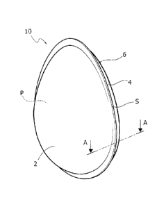
Figure 1 illustrates an example of package for a
product P, specifically an Easter egg, provided
according to the process described herein.
In general, this type of package, designated in
Figure 1 by the reference number 10, comprises a first
sheet of wrapping material 2 and a second sheet of
wrapping material 4 coupled together.
The sheet 2 has a portion for receiving the
product 2a, and a peripheral portion 2b that surrounds
the receiving portion 2a. Likewise, the sheet 4 has a
portion for receiving the product 4a and a peripheral
portion 4b that surrounds the receiving portion 4a.
The sheets 2 and 4 are coupled together so that
the receiving portions 2a, 4a together define a closed
cavity C in which the product P is housed, and so that
the peripheral portions 2b, 4b are set in contact with
one another so as to form a flange 6 surrounding the
cavity C (see Figure 1A).
With reference to Figure 1A, the flange 6 has a
sealing area 60 that hermetically closes the cavity C.
The sealing area 60 has a prevalent longitudinal
development and extends along a closed path that
surrounds the receiving portions 2a, 4a. This area is
substantially identifiable as a sealing strip.
The flange 6 is folded back on itself, identifying
a proximal part 6a and a distal part 6b joining
together along a folding line "s". Along the line "s"
the distal part 6b is folded back towards the cavity C,
against the proximal part 6a. It is to be noted that
Figure lA illustrates an enlargement that does not
respect the real proportions of the various elements,
having the purpose of enabling immediate understanding
CA 02840666 2014-01-23
. ,
of the structure of the flange 6; in this figure, the
folding line "s" is represented as a perimetral band.
However, in the real package the thicknesses of the
sheets 2 and 4 are so small, as compared to the
5 structure of the package, that the aforesaid band can
in actual fact be equated with a line, namely a folding
line.
In various embodiments, as in the one illustrated,
the portions for receiving the product 2a and 4a, which
together identify the cavity C, each reproduce the
conformation of the outer surface of the corresponding
part of the product P so as to be substantially
adherent to the product. This configuration enables the
package to reproduce, substantially identically, the
shape of the product contained therein. The receiving
portions 2a and 4a can hence be of any shape depending
only upon the shape of the packaged product, and may
consequently even differ from one another, for example
in the cases where the product has different opposite
faces. In this connection, there may, in general, also
be embodiments where the receiving portions 2a and 4a
are not both of a generic half-shell shape as in the
example illustrated, but, instead, one of them is
completely plane.
In various embodiments, as in the one illustrated,
the line of joining of the sheets 1 and 2 within the
cavity C is - throughout its extension or at least for
part thereof - directly in contact with the product P,
and the folding line "s" of the flange 6 extends
parallel thereto so that as a whole the flange
reproduces almost exactly the profile that the product
P has in the plane of the flange. The aesthetic effect
is that of greater enhancement of the overall form of
the product.
To make a package of the type described above the
CA 02840666 2014-01-23
,
,
,
,
6
process in question envisages in general the steps of:
- providing a first sheet of wrapping material,
which presents a first portion for receiving said
product and a first peripheral portion surrounding said
first receiving portion;
- providing a second sheet of wrapping material,
which presents a second portion for receiving said
product and a second peripheral portion surrounding
said second receiving portion;
- setting said product on said first receiving
portion or said second receiving portion;
- coupling said first sheet to said second sheet
so that said first and second portions for receiving
said product together define a closed cavity in which
said product is housed, and so that said first and
second peripheral portions are set in contact with one
another so as to form a flange surrounding said cavity;
- forming on said flange a sealing area that
hermetically closes said cavity; and
- folding said flange along a folding line such as
to define a proximal flange part and a distal flange
part connected to said proximal part through said
folding line, said distal part being folded back
towards said cavity, against said proximal part, by
said folding line.
The process described herein is characterized in
that it envisages providing said sealing area at a
minimum distance from the aforesaid first and/or second
receiving portions, which is such that, after said
folding step, said sealing area comes to be in said
distal part of said folded flange, and is not traversed
by said folding line.
The characteristic indicated, inherent in the
formation of the sealing area 60, entails that the next
folding step directly involves only non-sealed portions
CA 02840666 2014-01-23
,
,
,
7
of the flange 6, subjecting them to deformation, and
not, instead, also the sealing area itself. This makes
it possible to obtain a flange that is perfectly folded
back on itself, which stably remains in this condition,
without any risk of it elastically returning to a
splayed-out condition. In this connection, the present
applicant has in fact found that the above phenomenon
of elastic return arises when the folding step involves
instead - also or only - the sealing area, i.e., in the
cases where the latter is traversed by the folding line
"s"; the reason for this behaviour is to be put down to
the fact that, where the sheets 2 and 4 are welded
together, the flange 6 is as a whole more rigid, and
consequently assumes a mechanical
behaviour
substantially more elastic than the remaining parts.
The characteristic referred to above moreover
helps to solve the technical problem of preventing the
heat necessary for sealing the two sheets from at the
same time causing melting, or in any case a variation
of consistency, also of the product P, in the cases
where this is of a material that can melt, such as for
example chocolate. Provision of the sealing area at a
distance from to the portions for receiving the product
presupposes, in fact, that the sealing means themselves
are positioned at a distance from these portions (which
is already in itself able to reduce the amount of heat
coming from the sealing means that reaches the
product). In the space provided between the sealing
means and the product it is possible to insert means
for protecting the product from the heat generated by
the sealing means, thus preventing the heat from
possibly causing heating of the product.
Finally, it is to be noted that positioning of the
sealing area 60 on the distal portion 6b guarantees
that the perimetral end edges of the peripheral
CA 02840666 2014-01-23
= ,
,
,
8
portions 2b, 4b are joined together in a mutual
condition of perfect alignment, preventing the internal
sides thereof, which could be of a colour and an
appearance different from that of the external sides,
from becoming visible and/or preventing the aforesaid
portions from curling and not being perfectly laid out
on top of one another.
In view of the foregoing, it is hence evident that
the characteristic of providing the sealing area at the
aforesaid minimum distance from the portions for
receiving the product of the sheets 2 and 4 is
essential for obtaining an optimal aesthetic result on
the package.
The packaging process will now be described in
detail, in its different possible embodiments. For this
purpose, see Figures 2 to 25, which are schematic
illustrations that have the sole purpose of enabling an
immediate understanding of the principal aspects of the
process and of the means used for implementing it. In
particular, in what follows reference will be made to
the production of a single package, but it is clear
that the same means described may be easily configured
for producing simultaneously a number of packages at a
time.
The process first of all envisages providing the
first and second sheets of wrapping material 2 and 4
that will come to constitute the package. The sheets 2
and 4 are preferably made of a plastically deformable
material, typically aluminium, of a thickness of from
10 m to 40 m, and are coated with a layer made of
heat-meltable or heat-sealable material, for example
polyethylene or any other plastic material of a similar
type.
In various embodiments, as in the one illustrated,
the process envisages shaping of the first and second
CA 02840666 2014-01-23
9
sheets so as to define thereon the portions 2a and 4a
for receiving the product referred to in Figure 1.
In various embodiments, as in the one illustrated,
for this purpose the process envisages the use of
moulds 8' and 8", which have respective mould cavities
9 and 11 of a shape corresponding to complementary
portions of the outer surface of the product to be
packaged. The sheets 2 and 4 are arranged on the moulds
8' and 8", and for example with the aid of a plug 10,
of a shape complementary to the surface of the mould
cavity, are subjected to an operation of drawing via
which on the sheets 2 and 4 there are formed the parts
2a and 4a for receiving the product, surrounded,
respectively, by the peripheral portions 2b and 4b, of
a substantially plane conformation.
In various embodiments, as in the one illustrated,
the shaped sheets 2 and 4 are then transferred into the
auxiliary supports 12 and 14, which present respective
seats 16 and 18, for receiving the shaped parts 2a and
4a, and respective plane surfaces 20 and 22,
surrounding the seats 16 and 18 and suitable for
supporting the flange portions 2b and 4b. In various
embodiments, as in the one illustrated, one of these
supports, the support 12 in the example illustrated,
has an annular slot or groove 24 surrounding the seat
16 of the support, the function of which will be
illustrated in what follows.
In various embodiments, as in the one illustrated,
the supports 12 and 14 may be moved with respect to one
another between an open condition, for example
illustrated in Figure 4, and a closed condition, for
example illustrated in Figure 7, and moreover, in the
latter condition, may be rotated together, about an
axis orthogonal to the plane of the figures. The means
for providing said movements of the supports 12 and 14
CA 02840666 2014-01-23
,
,
,
,
may be of any type already known to the person skilled
in the sector and consequently will not be described
herein in detail.
In the condition illustrated in Figure 5, the
5 article P is positioned, by transfer means in
themselves known, for example of the suction-cup type,
in the receiving part 4a of the sheet 4, and, then, by
turning the support 14 over through 1800 on the support
12 (Figures 6 and 7), the sheet 2 is coupled to the
10 sheet 4, which overlies the surface portion of the
article P that emerges from the seat 18; there is thus
obtained a configuration in which the two sheets 2 and
4 are arranged with their peripheral portions 2b and 4b
in contact with one another to form the flange 6, and
with their receiving portions 2a and 4a that together
define the cavity C containing the product P. Then, the
supports 12 and 14 are brought back into their open
condition as illustrated in Figure 8.
The process described herein at this point
envisages providing the sealing area in order to close
the cavity C hermetically and at the same time join the
sheets 2 and 4 together.
As mentioned previously, the process described
herein is characterized in that the sealing area is
provided at a given minimum distance from the receiving
portions of the two sheets of wrapping material. The
value of this distance is selected in such a way that,
after the folding step, the sealing area comes to be
located on the distal part of the folded flange and is
not traversed by the folding line defined therein. This
value is thus a function of the width of the proximal
part of the folded flange and, in general, may be equal
to or greater than this width. The width of the same
sealing area - measured in a direction transverse to
the longitudinal direction of the area - cannot instead
CA 02840666 2014-01-23
11
be greater than the width of the distal part of the
folded flange.
In various embodiments, as in the one illustrated,
to obtain the sealing area the process described herein
envisages use of a sealing device 52.
The above device comprises, in general, supporting
means configured for receiving the sheets 2 and 4
coupled together, which identify a seat on which the
receiving portion 2a or 4a of these sheets is to be
arranged, and a preferably plane contrast surface, on
which the peripheral portions 2b, 4b are to be rested.
The device 52 further comprises a pressure element 54
presenting a heating edge 54a, which is driven by motor
means 53 so that the edge 54a presses the parts 2b, 4b
against the aforesaid contrast surface. In various
embodiments, as in the one illustrated, the above
supporting means are constituted by one of the supports
12 and 14 themselves, in this case the aforesaid seat
being constituted by the seats 16 and 18 of these
supports, whilst the aforesaid contrast surface is
constituted by their surfaces 20, 22. In alternative
embodiments, the supporting means in question are
instead constituted by a support altogether similar to
the supports 12 and 14 but uniquely designed for use
with the sealing device 52. In various preferred
embodiments, set on the aforesaid contrast surface is
an elastic element 44, for example made of silicone,
which presents a conformation such as to identify a
plane surface that substantially reproduces in shape
and dimensions the heating edge 54a, and against which
the latter presses the parts 2b, 4b. The element 44 has
the function of compensating, as a result of its
elastic consistency, any possible imperfections of the
contrast surface and/or of the heating edge. In various
embodiments, as in the one illustrated, the elastic
CA 02840666 2014-01-23
12
element 44 is received in a corresponding groove made
in the contrast surface 22.
In the region where the portions 2b, 4b are
pressed by the heating edge 54a, they are welded
together, as a result of the combined action of
pressure and heat applied by said edge. To obtain the
desired sealing area, the heating edge 54a has a width
corresponding to that of said sealing area, and extends
along a closed path of a length and/or shape
corresponding to the length and/or shape of the path
along which the sealing area will be located on the
portions 2b, 4b. In particular, the edge 54 extends
along a path such that, in the operative condition of
the element 54, it surrounds the receiving portions 2a,
4a, keeping at a distance equal at least to the
aforesaid minimum distance of the sealing area,
designated by H in Figure 10A.
As may be seen in Figures 10 and 10A, in the
aforesaid operative position of the element 54,
provided between the heating edge 54a and the shaped
part 4a is a free space. In various embodiments, as in
the one illustrated, the process envisages inserting
into the above space means designed to protect the
product P from the heat transmitted by the heating edge
54a.
For this purpose, in various embodiments, as in
the one illustrated, the device 52 comprises a cooling
body 56, set within the heating edge 54a and configured
for covering the shaped part 4a and the portion of
product contained therein, preventing any direct
exposure thereof to the heating edge 54a and absorbing
the heat transmitted by the edge itself. In particular,
the body 56 has a cavity 56a, designed to receive the
shaped part 4a, and an edge 56b, which surrounds the
cavity 56a and is of a width such as that it can fit
CA 02840666 2014-01-23
13
into the space between the edge 54a and the shaped part
4a.
The device 52 comprises means (not illustrated)
for circulation of a cooling fluid within the body 56.
In particular, the body 56 comprises one or more ducts
that are arranged around the cavity 56a, and supply
means are associated to these ducts, to obtain a
circulation of the cooling fluid through them. During
operation of the device, the cooling fluid absorbs the
heat emanating from the heating edge 54, thus
preventing this heat from possibly causing heating of
the portion 4a and of the product P.
The body 56 can be carried by the pressure element
54 itself, or else by a distinct movement structure,
driving of which is coordinated with the element 54.
In alternative embodiments, instead of the cooling
body 56 it is possible to envisage simply a body made
of insulating material that prevents transfer of the
heat generated by the heating edge 54a to the product
P.
The sealing device 52 described above may
constitute a station in the framework of a packaging
plant, which performs on the line one or more of the
operations described previously, or else may constitute
a stand-alone device to which the products P, along
with the sheets 2 and 4 associated thereto, can be fed
by the line of the plant.
At the end of the sealing operation, the sheets 2
and 4 are joined together to form a hermetically sealed
wrapper.
After the sealing step, the process described
herein finally envisages creating the folded flange of
the package.
In general, this step envisages folding the flange
6 on itself along the folding line "s" so as to
CA 02840666 2014-01-23
,
,
,
14
identify the proximal part 6a and the distal part 6b.
By the folding line "s", the distal part 6b is folded
back towards the cavity C, until it is brought up
against the proximal part 6a. From what has been said
previously, the operation of folding of the flange 6
does not subject the sealing area 60 to deformation,
and, at the end thereof, this area comes to be located
in the distal part 6b (see Figures lA and 15 to 23).
Optionally, prior to the operation of folding
referred to above, a cutting operation is envisaged to
reduce the flange 6 to the desired width.
In various embodiments, as in the one illustrated,
the operations of cutting and folding referred to above
are carried out using the methods and devices presented
in the patent No. EP2366631 discussed at the start,
which will also be described in detail hereinafter for
completeness of exposition. It is clear, however, that
the operations in question can be provided also via
alternative methods and/or devices. It is to be noted
in this connection that the advantages discussed above
linked to positioning of the sealing area at a distance
from the product P are clearly obtained also in the
case where methods and/or devices different from the
ones described in what follows are used.
In various embodiments, as in the one illustrated,
starting from the condition represented in Figure 11,
the wrapping material obtained by the sealing operation
is transferred from the support 14 to the support 12.
For this purpose, a movement of the supports 12 and 14
is performed comprising in succession: i) turning over
through 180 the support 12 on the support 14 (Figure
12); ii) turning over through 180 the set of the
supports 12 and 14 (Figure 13), so that the product and
the wrapping material pass from being carried by the
support 14 to being carried by the support 12; and
CA 02840666 2014-01-23
,
finally iii) removing the support 14 from the support
12 (Figure 14).
In various embodiments, as in the one illustrated,
the process then envisages an operation of cutting the
5 flange 6, aimed at obtaining the desired width of the
flange.
The above cutting operation is preferably
performed so as to realize, simultaneously with
cutting, folding of a distal portion of the above
10 flange at an angle, preferably of 900, with respect to
the remaining proximal portion so as to identify
already in this step the aforesaid proximal and distal
parts 6a and 6b that will come to form the folded
flange in the next process step.
15 In various
embodiments, as in the one illustrated,
this operation can be performed by means of a device of
the type illustrated in Figure 15, which co-operates
with the support 12, provided with the annular groove
24. This cutting device comprises a vertically mobile
support 26, associated to which is an annular cutting
or dinking member 28, and pressure means 30, 32,
preferably elastically constrained to the support 26,
which surround the annular cutting member 28 internally
and externally. The cutting device is positioned with
the pressure means 30, 32 in contact with the flange 6
and with the cutting member 28 that is able to
penetrate into the groove 24. The cutting end 28a of
the cutting member 28 is able to penetrate into the
groove 24 at a slight radial distance from the radially
internal wall 24a of the groove 24, this distance being
sized so that the folded flange part can be received
therein.
In this way, in the course of the cutting
operation, the pressure means 30, 32 constrain the
flange 6, and lowering of the cutting member inside the
CA 02840666 2014-01-23
, .
16
groove 24 causes, simultaneously with cutting of the
peripheral portions of the flange, simultaneous folding
downwards of the distal portion 6b with respect to the
proximal portion 6a. The offcuts, designated as a whole
by 13, can be removed after cutting, for example by
suction, in a next step of the process.
Then, the process preferably contemplates an
operation of turning-over through 1800 of the wrapping
material so as to position the folded flange parts
upwards. This operation may, for example, be performed
according to the operating steps of Figures 16, 17, 18,
and 19, which comprise turning over the support 14 on
the support 12 to obtain the configuration of Figure
17, where the wrapping material is closed between the
supports 12, 14, turning-over through 180 of the two
associated supports 12, 14 (Figure 18), and subsequent
opening of the top support 14 to obtain the
configuration of Figure 19.
The process then envisages folding the distal part
6b of the flange against the corresponding proximal
part 6a.
In various embodiments, as in the one illustrated,
in order to perform this operation, the process
described herein envisages the use of the crimping
device described in the European patent No. EE2366631.
The term "crimping", which in mechanical technologies
is used to indicate the operation of clinching the edge
of riveted sheets of metal, is here used in a sense
such as to indicate an operation of deformation,
folding and/or clinching of the flange 6.
The aforesaid device may constitute a station that
operates on the line in the framework of a packaging
plant, or else may constitute a stand-alone device to
which the wrappers to be treated can be supplied by the
line of the plant.
CA 02840666 2014-01-23
17
The device in question can be provided for co-
operating directly with one of the supports 12 or 14
described previously, or else, alternatively, it may
comprise its own means for supporting the wrapping
material, which, like the supports 12 and 14, in
general comprise a seat designed to support one of the
two shaped parts 4a or 2a of the wrapping material, and
a substantially plane surface, which surrounds the
aforesaid seat and is designed to support the flange 6.
The device in question comprises crimping means
provided for bringing about folding and/or clinching of
the distal part 6b with respect to the article P,
starting from a configuration of the type illustrated
in Figure 20, where this part is already folded in an
angled position, generally practically orthogonal to
the surface 22 of the support 14.
The aforesaid crimping means comprise a crimping
tool, designated by 36, which may be a body shaped like
a plate provided with an opening 38 (Figure 25), having
a homologous perimetral profile 40 enlarged with
respect to the perimetral profile defined by the end of
the flange 6.
The crimping tool 36 may thus be positioned in
contact with the surface 22 of the support 14, with the
opening 38 in a position surrounding, at a distance,
the distal portion 6b, i.e., in the configuration of
Figure 24, visible in which are the receiving portion
2a, the perimetral profile defined by the distal
portion 6b, and the profile 40 of the opening 38, which
is positioned at a practically uniform distance from
the portions 6a, 6b.
The crimping tool is vertically mobile with
respect to the supporting means between a raised
position and a lowered position, where it is
practically in contact with the surface 22. The
CA 02840666 2014-01-23
18
crimping tool 36 is likewise mobile in a horizontal
plane. Motor means 42 are provided for actuating the
crimping tool for the vertical and horizontal movement.
In particular, the motor means 42 are provided for
bringing consecutive or non-consecutive stretches of
the profile 40 of the opening 38 into contact with a
homologous stretch of the profile defined by the
previously folded distal portion 6h. This operation can
be performed in the position in which the bottom end of
the crimping tool is in contact with the surface 22 and
is useful also for achieving, whenever necessary, a
correct positioning of the distal portion 6b at right
angles to the surface 22 (Figure 20). Then, the
crimping tool is subjected to a vertical movement for a
distance d greater than the thickness of the flange 6
and such that the bottom end of the profile 40 and of
the opening 38 is still able to interfere, following
upon a horizontal displacement, with the top end of the
distal portion 6b (Figure 21).
Next, the crimping tool 36 is subjected to a
horizontal movement of approach to the body of the
article P so as to cause further folding inwards of the
distal portion 6b (Figure 22) in such a way that it is
set on top of the proximal portion 6a.
optionally and in any case preferably, the
crimping tool 36 is then subjected to a vertical
movement of approach to the surface 22 of the support
14, for carrying out clinching (Figure 23).
The aforesaid operations, i.e., the operations
represented in Figures 20, 21, and 22 and optionally
also the operations of Figure 23 (and clinching) are
carried out for further consecutive or non-consecutive
stretches of the profile of the flange. For instance,
when the article has a generally quadrangular profile,
the aforesaid operations are carried out for each side
CA 02840666 2014-01-23
19
defining the profile.
In various embodiments, as in the one illustrated,
in order to reach the consecutive or non-consecutive
stretches of the flange 6, the crimping tool is driven
according to a translational movement in two mutually
orthogonal directions. In the case of the ovoidal
profile represented in the figures, the crimping tool
may alternatively be pre-arranged for a rotary and
eccentric movement in the horizontal plane so as to
bring one after another consecutive or non-consecutive
stretches of the profile 40 of the opening 38 into
contact with the corresponding portions of the flange
6.
It is to be noted that performing the crimping
operation along the entire flange profile does not
constitute an essential and imperative aspect of the
process, in so far as - in given applications - it may
be desirable to maintain a portion of the flange
profile not crimped, i.e., maintain a stretch of the
flange profile not folded back on itself. The process
according to the invention thus also presents the
advantage of enabling execution of the crimping
operation only on a portion of the perimetral profile
of the flange or on specific portions thereof that may
even not be adjacent to one another.
As mentioned above, the final clinching operation
is optional. For instance, in the case of the ovoidal
body illustrated in the figures, the clinching
operation (whenever necessary) can be performed in a
subsequent stage with an auxiliary tool 36b (Figure
23), vertically mobile under the action of motor means
42a, and provided with an opening, the internal profile
of which substantially corresponds to the profile
formed by the folded distal part 6b (i.e., by the
folding line "s"). The aforesaid auxiliary tool 36b can
CA 02840666 2014-01-23
be driven in a vertical movement until it comes into
contact with the flange folded back on itself so as to
perform clinching along its entire contour, in a single
operation.
5 The crimping
device described makes it possible to
operate on articles of different shapes, by simply
modifying the profile 40 of the opening or openings 38.
Of course, without prejudice to the principle of
the invention, the details of construction and the
10 embodiments may vary, even significantly, with respect
to what is illustrated herein purely by way of non-
limiting example, without thereby departing from the
scope of the invention, as is defined by the annexed
claims.