Note: Descriptions are shown in the official language in which they were submitted.
CA 02840760 2013-12-30
Ammonia gas generator and method for generating ammonia for reducing nitrogen
oxides in exhaust
Description
The present invention relates to an ammonia gas generator for generating
ammonia from an
ammonia precursor substance, to a method for producing ammonia gas, and to the
use
thereof in exhaust treatment systems for reducing nitrogen oxides in exhaust.
The exhaust of internal combustion engines often contains substances of which
the release
into the environment is undesirable. Therefore, many countries set limits
which have to be
adhered to on the release of these pollutants, such as in the exhausts of
industrial facilities
or automobiles. These pollutants include nitrogen oxides (NO,), such as in
particular
nitrogen monoxide (NO) or nitrogen dioxide (NO2), as well as a range of other
pollutants.
The release of these nitrogen oxides from the exhaust of combustion engines
can be
reduced in various ways. At this point, emphasis should be placed on reduction
by way of
additional exhaust treatment measures, in particular based on selective
catalytic reduction
(SCR). What these methods have in common is that a reducing agent which acts
selectively
on the nitrogen oxides is added to the exhaust, the nitrogen oxides thus being
converted in
the presence of a corresponding catalyst (SCR catalyst). This converts the
nitrogen oxides
into substances which are less harmful to the environment, such as nitrogen
and water.
One reducing agent for nitrogen oxides which is already used nowadays is urea
(H2N-
CO-NH2), which is added to the exhaust in the form of an aqueous urea
solution. In this
context, the urea in the exhaust stream may break down into ammonia (NH3), for
example as a result of the action of heat (thermolysis) and/or a reaction with
water
(hydrolysis). The ammonia which is thus formed is the actual reducing agent
for nitrogen
oxides.
Exhaust treatment systems for automobiles have been being developed for some
time,
and this is discussed in numerous publications. Thus for example European
patent EP
487 886 B1 discloses a method for selective catalytic NO, reduction in oxygen-
containing
exhaust of diesel engines, in which urea and the thermolysis products thereof
are used as
CA 02840760 2013-12-30
2
reducing agents. In addition, a device for generating ammonia in the form of a
tubular
evaporator is disclosed, and comprises a spraying device, an evaporator
comprising an
evaporator tube, and a hydrolysis catalyst.
Further, European patent EP 1 052 009 B1 discloses a method and a device for
carrying
out the method for thermal hydrolysis and metering of urea or urea solutions
in a reactor
with the aid of a partial exhaust stream. In the method, a partial stream of
the exhaust is
removed from an exhaust line upstream from the SCR catalyst and passed through
the
reactor, the partial stream, which is loaded with ammonia after the hydrolysis
in the
reactor, likewise further being passed back into the exhaust line again
upstream from the
SCR catalyst.
In addition, European patent EP 1 338 562 B1 discloses a device and method
which
make use of the catalytic reduction of nitrogen oxides by ammonia. In this
context, the
ammonia is obtained from urea in solid form under flash thermolysis conditions
and
from isocyanic acid by hydrolysis, and supplied to the exhaust stream of a
vehicle.
Further, European patent application EP 1 348 840 Al discloses an exhaust
purification
system in the form of an assembly, which can be transported as a whole unit,
in the form of
a 20-foot container. The system is operated in such a way that a urea or
ammonia solution
is injected into the exhaust stream directly by means of an injection device.
The nitrogen
oxides contained in the exhaust are reduced on an SCR catalyst.
Further, German patent application DE 10 2006 023 147 Al discloses a device
for
generating ammonia which is part of an exhaust treatment system.
In addition, international applications WO 2008/077 587 Al and WO 2008/077 588
Al
disclose a method for the selective catalytic reduction of nitrogen oxides in
exhausts of
vehicles by means of aqueous guanidinium salt solutions. This method uses a
reactor
which generates ammonia from the aqueous guanidinium salt solutions.
Even though ammonia gas generators have been known for some time, thus far the
technology has not been implemented in a vehicle or any other application.
Thus far, the
concept of direct injection of an ammonia precursor substance into the exhaust
stream of
an internal combustion engine has been pursued, this ammonia precursor
substance
being broken down into the actual reducing agent in the exhaust stream by
suitable
CA 02840760 2014-01-10
3
measures. However, as a result of incomplete decomposition or secondary
reactions of
decomposition products in the exhaust line, depositions are always observed,
and
damage the catalysts and filters which are also present in the exhaust line.
Therefore, an object of the present invention is to provide an ammonia gas
generator
and a method for producing ammonia which overcome these drawbacks of the prior
art.
A further object of the present invention is to provide an ammonia gas
generator which is
of a simple construction, provides a high conversion rate of ammonia precursor
substances into ammonia gas, and makes long-term use without maintenance
possible.
In addition, it should be possible to use the ammonia gas generator
universally, it also
being possible in particular to use different types of ammonia precursor
substances.
Further, the method for generating ammonia should be able to be carried out by
simple
apparatus measures, provide a high conversion rate of ammonia precursor
substances
into ammonia gas, and make long-term use without maintenance possible.
These problems are solved by an ammonia gas generator described herein and by
a
method for generating ammonia from a solution of an ammonia precursor
substance by
means of an ammonia gas generator described herein. Thus, in accordance with a
first
embodiment, the subject matter of the present invention is an ammonia gas
generator, for
generating ammonia from a solution of an ammonia precursor substance, which
comprises
a catalyst unit, the catalyst unit in turn comprising a catalyst for
decomposing and/or
hydrolysing ammonia precursor substances into ammonia and a mixing chamber
upstream
from the catalyst, and the catalyst being of a catalyst volume VKat and the
mixing chamber
being of a mixing chamber volume Vmisch. Further, the ammonia gas generator
comprises
an injection device for introducing a solution of the ammonia precursor
substance into the
mixing chamber and an outlet for the ammonia gas formed, the ammonia gas
generator
comprising an inlet for a carrier gas which generates a tangential carrier gas
stream with
respect to the solution injected into the mixing chamber.
In accordance with one aspect of the present invention, there is provided an
ammonia gas
generator (100) for generating ammonia from a solution of an ammonia precursor
substance, comprising - a catalyst unit (70), which comprises a catalyst (60)
for
decomposing and/or hydrolysing ammonia precursor substances into ammonia and a
mixing
chamber (51) upstream from the catalyst (60) in the flow direction, the
catalyst (60) being of
a catalyst volume VKat and the mixing chamber (51) being of a mixing chamber
volume Vrviiõth
CA 02840760 2014-01-10
3a
- an injection device (40) for introducing the solution of the ammonia
precursor substance
into the mixing chamber (51) and - an outlet (80) for the ammonia gas which is
formed, the
ammonia gas generator comprising an inlet (56) for a carrier gas which
generates a
tangential carrier gas stream with respect to the solution injected into the
mixing chamber
(51), characterised in that the catalyst unit (70) comprises a hydrolysis
catalyst which is at
least divided in two, the first part of which in the flow direction is in the
form of a heated
catalyst, and the second part of which is in the form of an unheated catalyst,
or in that two
hydrolysis catalysts are arranged one behind the other, the first hydrolysis
catalyst being a
heated catalyst and the second hydrolysis catalyst being an unheated catalyst.
In accordance with another aspect of the present invention, there is provided
a method for
generating ammonia from a solution of an ammonia precursor substance by means
of an
ammonia gas generator (100) comprising - a catalyst unit (70), which comprises
a catalyst
(60) for decomposing and/or hydrolysing ammonia precursor substances into
ammonia and
a mixing chamber upstream from the catalyst (60) in the flow direction, the
catalyst being of
a catalyst volume VKat and the mixing chamber being of a mixing chamber volume
Vmsch, - an
injection device (40) for introducing the solution of the ammonia precursor
substance into the
mixing chamber (51), - an outlet (80) for the ammonia gas which is formed, the
solution of
the ammonia precursor substance being introduced into the mixing chamber (51)
separately
from a carrier gas and the carrier gas being introduced tangentially to the
solution of the
ammonia precursor substance, characterised in that the catalyst unit (70)
comprises a
hydrolysis catalyst which is at least divided in two, the first part of which
in the flow direction
is in the form of a heated catalyst, and the second part of which is in the
form of an unheated
catalyst, or in that two hydrolysis catalysts are arranged one behind the
other, the first
hydrolysis catalyst being a heated catalyst and the second hydrolysis catalyst
being an
unheated catalyst.
At this point, it should be emphasised that an ammonia gas generator according
to the
present invention is a separate unit for generating ammonia from ammonia
precursor
substances. A unit of this type may for example be used for reducing nitrogen
oxides in
industrial exhausts or for exhaust treatment of exhaust from combustion
engines, such as
diesel engines. This ammonia gas generator may also operate independently or
be
operated using lateral exhaust streams, although in any event nitrogen oxides
are not
reduced by means of ammonia until a subsequent process step. If an ammonia gas
CA 02840760 2013-12-30
4
generator according to the invention is used as a separate component in an
exhaust
treatment system of a combustion engine, for example of a diesel engine, the
nitrogen
oxides in the exhaust stream can thus be reduced without introducing further
catalysts for
breaking down ammonia precursor substances or other components into the
exhaust
stream itself. The ammonia produced using the ammonia gas generator according
to the
invention can thus be introduced into the exhaust stream as required. A
potential decrease
in the service life of the SCR catalyst due to impurities in the form of
depositions, for
example of ammonia precursor substances or decomposition products of ammonia
precursor substances, is also prevented.
Thus, according to the invention, an ammonia precursor substance is not
supplied to an
exhaust stream, ammonia subsequently being formed in situ from the ammonia
precursor
substance and acting as a reducing agent in the exhaust stream. Instead,
according to
the invention, ammonia is supplied to the exhaust stream, having been formed
in
advance in a separate unit, specifically the ammonia gas generator according
to the
invention. Thus, according to the invention, ammonia is in particular
initially generated
from an ammonia precursor substance in an ammonia gas generator as a separate
unit.
This ammonia, and not the ammonia precursor substance, is subsequently
introduced
into an exhaust stream, in particular so as to bring about reduction of
nitrogen oxides
therein.
The supply of the ammonia takes place according to the invention preferably
upstream
from an SCR catalyst which is located in the exhaust stream. Further, the
supply of the
ammonia preferably takes place downstream from the combustion engine. In a
further
preferred embodiment, the supply of the ammonia takes place downstream from an
oxidation catalyst located in the exhaust stream.
It is essential to the invention that the ammonia gas generator comprises an
inlet for a
carrier gas which generates a tangential carrier gas stream with respect to
the solution
injected into the mixing chamber.
The inlet for the carrier gas is preferably located in the mixing chamber.
Surprisingly, it has been found that, as a result of the tangential carrier
gas stream (also
referred to as the transport gas stream in the following), depositions on the
walls of the
catalyst unit in the region of the mixing chamber can be further inhibited,
and it can be
CA 02840760 2013-12-30
provided that the carrier gas (also referred to as the transport gas in the
following) and the
solution of the ammonia precursor substance are constantly thoroughly mixed.
If a
tangential carrier gas stream of this type is not used, the wall of the
catalyst unit in the
region of the mixing chamber can be wetted by spraying the solutions of
ammonia
precursor substance into the mixing chamber, and undesired secondary reactions
such as
polymerisation of the ammonia precursor substance can take place. These
secondary
reactions lead to undesired depositions in the region of the mixing chamber,
as a result of
which constant thorough mixing of the carrier gas and the solution of the
ammonia
precursor substance, which mixing is exceptionally important for the operation
of the
generator, is no longer made possible. Due to the lack of thorough mixing of
the carrier gas
with the solution, additional depositions in and on the catalyst itself can
also be observed.
As a result of the tangential carrier gas stream, an eddy mist current
comprising the
droplets is generated, and is guided axially in the direction of the
hydrolysis catalyst onto
the hydrolysis catalyst end face. This eddy mist current makes very good
conversion into
ammonia possible on the catalyst. The tangential supply of the carrier gas is
provided in
the head region of the generator, preferably at the level of the spraying
device of the
ammonia precursor solution into the catalyst unit or into the mixing chamber.
In this
context, the gas stream is introduced as shallowly as possible against the
wall of the
mixing chamber, in such a way that a downwardly directed eddy current in the
catalyst unit
in the direction of the catalyst end face sets in.
The carrier gas, and in particular the tangential carrier gas stream, is
preferably introduced
into the mixing chamber at a temperature of up to 550 C, preferably at a
temperature of
250 to 550 C, more preferably at a temperature of 250 to 400 C and most
preferably at a
temperature of 300 to 350 C.
Ideally, in other words so as to achieve a conversion of the ammonia precursor
substance
into ammonia of more than 95 % and prevent the precursor substance from
contacting the
generator wall, particular decisive conditions are preferably met during
metering.
Preferably, injection of the ammonia precursor substance into the mixing
chamber is
carried out in such a way that, for a given catalyst end face, the spray cone
diameter upon
incidence on the catalyst end face is at most 98 %, preferably at most 95 %,
of the catalyst
diameter. By contrast, the spray cone diameter is preferably at least 80 %,
more
preferably at least 83 %, of the catalyst end face diameter so as to prevent
an excessively
high concentration for a given area and thus excessive loading of the end face
with
precursor substance. Excessive loading of the catalyst end face leads to
insufficient
CA 02840760 2013-12-30
6
contact with the catalyst and to excessive cooling as a result of the
evaporating liquid, and
thus likewise to incomplete conversion and to undesired secondary reactions
which are
connected with depositions. Ideally, this therefore results in combinations
which are
preferably to be used of a tangential carrier gas stream with further
parameters which are
specified by the injection device. In this context, in particular the type of
the injection
device to be used and the distance of the opening of the injection device from
the given
catalyst end face should be mentioned.
In connection with the present invention, an injection device should be
understood to be
any device which sprays, atomises or otherwise forms into drops a solution,
preferably an
aqueous solution, of an ammonia precursor substance, the solution of the
ammonia
precursor substance being in the form of drops which in particular have a
droplet
diameter d32 of less than 25 pm. In connection with the present invention, the
droplet
diameter d32 relates to the Sauter mean diameter according to the German
industry
standard DIN 66141.
Thus, in accordance with a preferred embodiment of the present invention, it
is provided
that the injection device in turn comprises a nozzle which generates droplets
having a
droplet diameter d32 of less than 25 pm. In this context, according to the
present
invention, it is preferably further provided that the nozzle generates
droplets having a
droplet diameter d32 of less than 20 pm and most preferably less than 15 pm.
Simultaneously or independently, it is further preferred for the nozzle to
generate droplets
having a droplet diameter d32 of more than 0.1 pm and in particular more than
1 pm.
When nozzles of this type are used, an ammonia formation level AG of > 95 %
(see
above) can also be achieved. In addition, a particularly uniform distribution
of the solution
on the catalyst end face can be achieved. In this context and in the
following, the
ammonia formation level AG is defined as the molar amount of NH3 generated in
the
method with respect to the molar amount of ammonia which should theoretically
be
generated by complete hydrolysis of the ammonia precursor substance. According
to the
present invention, an ammonia formation level of > 95 % is considered to be
complete
conversion.
In accordance with a particularly preferred variant, it may in particular be
provided that the
injection device in turn comprises a nozzle which is what is known according
to the
present invention as a two-substance nozzle. In this context, a two-substance
nozzle is
understood to be a nozzle which uses a pressurised gas, generally air, as a
propellant for
CA 02840760 2013-12-30
7
breaking up the surface of the liquid phase and thus for droplet formation.
This
pressurised gas is also referred to as atomisation air. This form of the
nozzle makes
particularly fine distribution of the ammonia precursor substance possible,
along with a
droplet diameter d32 of less than 25 pm, in particular less than 20 pm.
In this context, the propellant, in particular the atomisation air, is
preferably introduced
into the mixing chamber together with the solution of the ammonia precursor
substance,
through the same nozzle opening.
Independently or simultaneously, the injection device may also comprise at
least two
nozzles, which can in particular be switched jointly or separately, for
introducing the
ammonia precursor substance into the mixing chamber.
Alternatively, however, it may also be provided that the injection device
comprises what is
known as a flash evaporator.
The spray cone according to the present invention is the cone of the solution
to be
sprayed which can be generated using a nozzle or a plurality of nozzles having
a defined
spray angle a, the spray cone diameter being the diameter which is obtained
when the
droplets are incident on the catalyst end face. This is set by the liquid
pressure of 0.1 to
bar on the solution to be sprayed at 25 C and optionally by the atomisation
air in the
operating range of 0.5 to 10 bar (for two-substance nozzles) when using
carrier gas.
In order to achieve a spray cone diameter of at most 98 % of the catalyst
diameter, it
can also be provided in accordance with a development of the present invention
that
the injection device in turn comprises at least one nozzle, in particular a
two-substance
nozzle which has a theoretical spray angle a of 10 to 90 . In particular, it
can
simultaneously or independently be provided that the distance of the nozzle
opening
from the end face of the catalyst is 15 to 2000 mm.
Particularly preferable is a nozzle, in particular a two-substance nozzle,
which has a
theoretical spray angle a of at least 10 , in particular at least 20 , in
particular at least 25 ,
particularly preferably of at least 30 , particularly preferably of at least
35 , particularly
preferably of at least 400 and most preferably of at least 450. Simultaneously
or
independently, nozzles are further preferred which have a theoretical spray
angle a of at
most 90 , in particular of at most 80 , in particular of at most 75 , in
particular of at most
CA 02840760 2013-12-30
8
70 , particularly preferably of at most 65 , particularly preferably of at
most 60 , particularly
preferably of at most 55 and most preferably of at most 500. As stated
previously, by way
of targeted use of a nozzle having a defined spray angle a, a uniform
distribution of the
solution to be sprayed can be achieved, without depositions occurring on the
walls of the
catalyst end face.
According to the present invention, the theoretical spray angle a (also
referred to as the
spray angle a in the following) should be understood to be a spray angle which
is set at
the outlet of the nozzle opening or nozzle openings with an operating pressure
of 0.1 to 10
bar on the solution to be sprayed at 25 C and optionally with the atomisation
air in the
operating range from 0.5 to 10 bar (for two-substance nozzles), without a
carrier gas or
any other influence on the sprayed solution being present.
A similar effect is produced if a nozzle is used which comprises a first
number of nozzle
openings for introducing the solution of the ammonia precursor substance into
the
catalyst unit, which are annularly surrounded by a second number of nozzle
openings
for introducing a carrier gas or atomisation air into the catalyst unit.
Alternatively, it may also be provided that at least one inlet for carrier gas
is provided
around the nozzle and is formed in such a way that the carrier gas forms a
casing around
the solution introduced into the mixing chamber. In this way, the sprayed
solution is
enclosed in a casing of carrier gas, in such a way that no wetting of the
inner wall is
observed.
In a further embodiment, the invention therefore relates to an ammonia gas
generator
which comprises at least one inlet for a carrier gas. The inlet is preferably
located in the
mixing chamber and is in particular separate or separated from the nozzle
opening
through which the solution of the ammonia precursor substance is introduced.
The carrier
gas may thus be introduced independently of the ammonia precursor substance
solution.
The inlet preferably generates a tangential or parallel carrier gas stream
with respect to
the solution injected into the mixing chamber. For a parallel carrier gas
stream, one or
more inlet openings for carrier gas are preferably arranged in the same wall
in which the
injection device for introducing the solution of the ammonia precursor
substance is
located.
In the present invention, it is further provided that the distance of the
nozzle opening from
CA 02840760 2013-12-30
9
the end face of the catalyst can comprise in particular from 15 to 1500 mm,
particularly
preferably from 15 to 1000 mm and most preferably from 15 to 800 mm.
Independently or
simultaneously, however, it may also be provided that the distance of the
nozzle opening
from the end face of the catalyst is at least 30 mm, preferably at least 40
mm, particularly
preferably at least 50 mm, particularly preferably at least 60 mm,
particularly preferably at
least 100 mm and most preferably at least 300 mm, and further independently or
simultaneously at most 1500 mm, in particular at most 1000 mm, in particular
at most 800
mm, in particular at most 500 mm, in particular at most 400 mm, particularly
preferably at
most 200 mm and most preferably at most 150 mm.
In accordance with a development of the present invention, it is also provided
that the ratio
of the volume of the mixing chamber Vmiõh to the volume of the catalyst VKat
is a ratio of 1.5
: 1 to 5: 1. Surprisingly, it has been found that the sprayed ammonia
precursor substance
can be broken down completely (conversion > 95 %) into ammonia if the droplets
of the
solution are evaporated in part in advance prior to incidence on the catalyst
end face. This
may be ensured in that the volume of the mixing chamber is greater than the
volume of the
catalyst. By way of partial evaporation of the droplets, the solution is
already supplied with
enough energy to prevent excessive cooling on the catalyst end face as a
result of
excessively large drops, and thus poor decomposition or by-product formation
is
countered. In addition, a corresponding mixing chamber volume Vmisch ensures
that the
sprayed ammonia precursor substance is incident on the catalyst, distributed
over the
cross-section of the catalyst homogeneously in the transport gas stream, as an
aerosol,
and spots having an excessive concentration, which would in turn lead to
poorer
conversion, are prevented. In this context, it is most preferably provided
that the ratio of the
volume of the mixing chamber Vmisch to the volume of the catalyst VKat is from
2.5 : 1 to 5 :
1, particularly preferably 3: 1 to 5: 1 and most preferably 3.5: 1 to 5: 1.
The volume of the catalyst VKat is preferably 50 ml to 1000 I. The volume of
the mixing
chamber Vmjsch is preferably at least 10 ml, preferably at least 50 ml, more
preferably at
least 100 ml, more preferably at least 200 ml, more preferably at least 1000
ml, more
preferably at least 2000 ml and more preferably at least 5000 ml.
Simultaneously or
independently, the volume of the mixing chamber Vmsch is preferably at most
2.5 I, more
preferably at most 10 I, more preferably at most 80 I, more preferably at most
500 I, more
preferably at most 1200 I and more preferably at most 2000 I.
Further, in accordance with the present invention a catalyst unit should be
understood to
CA 02840760 2013-12-30
be a unit which comprises a housing for receiving a catalyst, a mixing chamber
which is
upstream from the catalyst in the flow direction, and at least one catalyst
for decomposing
and/or hydrolysing ammonia precursor substances into ammonia, the catalyst
having a
catalyst volume VKat and the mixing chamber having a mixing chamber volume
Vmisch=
Optionally, the catalyst unit may additionally comprise an outlet chamber
which is
downstream from the catalyst in the flow direction for outputting the ammonia
gas formed.
In the context of the present invention, any catalyst which makes it possible
to release
ammonia from the precursor substance under catalytic conditions may be used as
the
catalyst for decomposing and/or hydrolysing ammonia precursor substances. A
preferred
catalyst hydrolyses the ammonia precursor substance to form ammonia and
further
harmless substances such as nitrogen, carbon dioxide and water. The catalyst
is thus
preferably a hydrolysis catalyst.
If for example a guanidinium salt solution is used, in particular a guanidium
formate
solution or a urea solution or mixtures thereof, the catalytic decomposition
into ammonia
may take place in the presence of catalytically active, non-oxidation-active
coatings of
oxides, selected from the group of titanium dioxide, aluminium oxide and
silicon dioxide
and mixtures thereof, and/or hydrothermically stable zeolites, which are fully
or partially
metal-exchanged, in particular iron zeolites of the ZSM 5 or BEA type. In this
context, in
particular the subgroup elements and preferably iron or copper are
possibilities for the
metals. The metal oxides, such as titanium oxide, aluminium oxide and silicon
dioxide,
are preferably applied to metal carrier materials such as heating line alloys
(in particular
chromium aluminium steels).
Particularly preferred catalysts are hydrolysis catalysts which in particular
comprise
catalytically active coatings of titanium dioxide, aluminium oxide and silicon
dioxide and
mixtures thereof.
Alternatively, catalytic decomposition of the guanidium formate solutions or
the remaining
components to form ammonia and carbon dioxide may also be provided,
catalytically
active coatings of oxides, selected from the group of titanium dioxide,
aluminium oxide
and silicon oxide and mixtures thereof, and/or hydrothermally stable zeolites,
which are
fully or partly metal-exchanged, are used, and are impregnated with gold
and/or
palladium as oxidation-active components. The corresponding catalysts
comprising
palladium and/or gold as active components preferably have a precious metal
content of
CA 02840760 2013-12-30
11
0.001 to 2 % by weight, in particular 0.01 to 1 % by weight. Using oxidation
catalysts of
this type, it is possible to prevent the undesired formation of carbon
monoxide as a by-
product during the decomposition of the guanidinium salt during the generation
of
ammonia.
Preferably, a catalytic coating comprising palladium and/or gold as active
components,
having a precious metal content of 0.001 to 2 % by weight, in particular 0.01
to 1 % by
weight, is used for the catalytic decomposition of the guanidium formate and
optionally the
further components.
Thus, a further subject matter of the present invention is an ammonia gas
generator
which comprises a catalyst which is in particular a hydrolysis catalyst, the
catalyst
comprising a catalytically active coating which is impregnated with gold
and/or
palladium, in particular having a gold and/or palladium content of 0.001 to 2
% by
weight (with respect to the catalytic coating). More preferably, this catalyst
comprises
a catalytically active coating of oxides selected from the group of titanium
dioxide,
aluminium oxide and silicon dioxide and mixtures thereof, and/or
hydrothermally
stable zeolites, which is impregnated with gold and/or palladium, the content
of gold
and/or palladium more preferably being 0.001 to 2 % by weight (with respect to
the
catalytic coating).
In the context of the present invention, it is possible to use a hydrolysis
catalyst which
consists of at least two portions, in the flow direction, the first portion
containing non-
oxidation-active coatings and the second portion containing oxidation-active
coatings.
Preferably, 5 to 90 % by volume of this catalyst consists of non-oxidation-
active coatings
and 10 to 95 % by volume consists of oxidation-active coatings. In particular,
15 to 80 %
by volume of this catalyst consists of non-oxidation-active coatings and 20 to
85 % by
volume consists of oxidation-active coatings. Alternatively, the hydrolysis
may also be
carried out in the presence of two catalysts arranged in series, the first
catalyst
containing non-oxidation-active coatings and the second catalyst containing
oxidation-
active coatings. More preferably, the first hydrolysis catalyst may also be a
heated
catalyst and the second hydrolysis catalyst may be an unheated catalyst.
Moreover, it may be provided to use a hydrolysis catalyst which consists of at
least two
portions, the first portion, arranged in the flow direction, being in the form
of a heated
catalyst and the second portion, arranged in the flow direction, being in the
form of an
CA 02840760 2013-12-30
12
unheated catalyst. Preferably, 5 to 50 % by volume of the catalyst consists of
the first
portion and 50 to 95 % by volume consists of the second portion.
According to a particularly preferred embodiment of the present invention, it
is therefore
provided that the ammonia gas generator comprises a catalyst unit comprising a
hydrolysis catalyst which is at least divided in two, particularly preferably
at least divided
into three, of which the first part in the flow direction is configured as a
heated catalyst
which preferably comprises a direct electrical resistance heater and/or a
jacket heater,
while the second part is configured as an unheated catalyst which is most
preferably
followed downstream by a third part configured as an unheated catalyst having
a mixer
structure.
An ammonia gas generator is particularly preferred which comprises a catalyst
unit of
which the catalyst has a ratio of the diameter of the catalyst DKat to the
length L of the
catalyst of 1 : 1 to 1 : 5, in particular of 1 : 2 to 1 : 4 and most
preferably of 1 : 3. The
catalyst diameter DKat is preferably 20 to 2000 mm, in particular 30 to 1000
mm and even
more preferably 30 to 100 mm. However, it may also be provided that the
diameter DKat is
30 to 80 mm, 80 to 450 mm or 450 to 1000 mm.
In this context, it is further preferred for the catalyst to be of a length L
of 30 mm to 2000
mm, particularly preferably of 70 mm to 1000 mm and most preferably of 70 mm
to 700
mm.
It has been found that, for complete catalytic conversion of the ammonia
precursor
substances, catalysts having a catalyst cell count of at least 60 cpsi (cpsi:
cells per
square inch ¨ cell count on the end face of the catalyst) and the catalyst
volumes
already described above are preferably used. In this context, the increasing
counter
pressure (loss of pressure by way of the catalyst) limits the catalyst cell
count to at most
800 cpsi for an application in an ammonia gas generator. Catalysts, in
particular
hydrolysis catalysts, are particularly preferred which have a catalyst cell
count of 100 to
600 cpsi on the end face, of to 100 to 500 cpsi on the end face and most
preferably of
100 to 400 cpsi on the end face of the catalyst.
As regards the configuration of the catalyst unit, it has been found in the
tests that a
cylindrical construction is particularly suitable. In this case, the
tangential carrier gas
stream can take full effect. By contrast, other constructions are less
suitable, since in this
CA 02840760 2013-12-30
13
case an excessively strong turbulence can be observed. Thus, a further subject
matter of
the present invention is an ammonia gas generator which comprises a catalyst
unit which
is in the form of a cylinder.
Moreover, it has been found to be particularly advantageous for the ammonia
gas
generator to comprise a catalyst unit which in turn comprises at least one
thermal
insulation layer, in particular a thermal insulation layer of microporous
cladding
material.
According to the present invention, ammonia precursor substances are
understood to be
chemical substances which can be placed in solution and which can split off or
otherwise
release ammonia by physical and/or chemical processes. According to the
present
invention, in particular urea, urea derivatives, guanidine, biguanidine and
salts of these
compounds and salts of ammonia may be used as ammonia precursor compounds.
According to the present invention, in particular urea and guanidine or salts
thereof can
be used. In particular the salts which are formed from guanidines and organic
or inorganic
acids may be used. In this context, guanidinium salts of general formula (I)
should be
considered to be particularly preferred,
T'NH2
X Xe
R--NH NH2
(I)
where
R = H, NH2 or C1-C12 alkyl,
XG= acetate, carbonate, cyanate, formate, hydroxide, methylate or oxalate.
Guanidium formate is particularly preferred.
CA 02840760 2013-12-30
14
In the context of the present invention, these guanidinium salts may be used
in the form of
an individual substance or a mixture of two or more different guanidinium
salts. In
accordance with a preferred embodiment, the guanidinium salts which are used
according
to the invention are combined with urea and/or ammonia and/or ammonium salts.
Alternatively, however, in accordance with a further embodiment of the present
invention
aqueous urea solutions may also be used. The mixing ratios of guanidinium salt
with urea
and ammonia or ammonium salts can be varied within wide limits. However, it
has been
found to be particularly advantageous if the mixture of guanidinium salt and
urea has a
guanidinium salt content of 5 to 60 % by weight and a urea content of 5 to 40
% by weight,
in particular of 5 to 35 % by weight. Further, mixtures of guanidinium salts
and ammonia or
ammonium salts having a guanidinium salt content of 5 to 60 % by weight and an
ammonia or ammonium salt content of 5 to 40 % by weight should be considered
to be
preferred. Alternatively, however, a urea solution, in particular an aqueous
urea solution,
may be used.
Compounds of general formula (II) have been found to be particularly
expedient as ammonium salts,
R¨NH39 X
(II)
where
R = H, NH2 or C1-C12 alkyl,
X -= acetate, carbonate, cyanate, formate, hydroxide, methylate or oxalate.
The ammonia precursor substances which are used according to the invention, in
particular guanidinium salts, or optionally the further components, consisting
of urea or
ammonium salts, are used in the form of a solution, predominantly water and/or
a C1-C4
alcohol preferably being used as the solvent. In this context, the aqueous
and/or
alcoholic solutions have a preferred solids content of 5 to 85 % by weight, in
particular 30
to 80 % by weight.
In this context, it has surprisingly been found that according to the present
invention both
aqueous guanidium formate solution in a concentration of 20 to 60 % by weight
and
CA 02840760 2013-12-30
aqueous urea solution in a concentration of 25 to 40 A by weight, as well as
aqueous
mixtures of guanidium formate and urea solutions, the mixture containing
guanidium
formate and urea at a concentration of 5 to 60 % by weight guanidium formate
and 5 to
40 % by weight urea, may particularly expediently be used.
In this context, the aqueous solution of the ammonia precursor substances, in
particular
the guanidinium salts, the mixtures of guanidinium salts or the guanidinium
salts in
combination with urea in water have a preferred ammonia formation potential of
0.2 to
0.5 kg ammonia per litre of solution, in particular 0.25 to 0.35 kg ammonia
per litre of
solution.
According to a further aspect, a method for generating ammonia from a solution
of an
ammonia precursor substance by means of an ammonia gas generator, in
particular a
method for continuously generating ammonia, more preferably by means of an
ammonia
gas generator described hereby, is a further subject matter of the present
invention. This
ammonia gas generator comprises a catalyst unit, which comprises in turn a
catalyst for
decomposing and/or hydrolysing ammonia precursor substances into ammonia and a
mixing chamber upstream from the catalyst in the flow direction, the catalyst
being of a
catalyst volume VKat and the mixing chamber being of a mixing chamber volume
Vmisch=
Further, the ammonia gas generator comprises an injection device for
introducing the
solution of the ammonia precursor substance into the mixing chamber and an
outlet for
the ammonia gas formed. It is essential to the invention that in the new
method, the
solution of the ammonia precursor substance is introduced into the mixing
chamber
separately from a carrier gas and the carrier gas is introduced tangentially
to the solution
of the ammonia precursor substance.
Due to the solution of the ammonia precursor substance being introduced
separately from
the carrier gas, targeted metering of the required energy amount or the heat
flow can be
produced for error-free, continuous operation of the generator. It has been
found that the
method can be produced by a sufficient amount of energy at a corresponding
temperature
level without resulting in undesired by-products. Complete decomposition of
the ammonia
precursor solutions which can be used into ammonia at a given amount or volume
flow of
solution requires a corresponding amount or volume flow of energy in the form
of heat at a
temperature level which is required for complete decomposition. The
temperature level is
determined in this case by the hydrolysis catalyst which is used. The energy
which is
predominantly introduced into the method preferably comes from the carrier gas
stream.
CA 02840760 2013-12-30
16
According to the invention, an ammonia gas generator is to be operated in
particular
technically and economically if the energy introduced for the decomposition of
the
ammonia precursor solution from the waste heat of the carrier gas is used. In
this context,
the amount of carrier gas does not automatically correlate to the metered
amount of the
liquid solution, since the usable amount of energy of the carrier gas varies
with the
temperature. A carrier gas stream at a slightly lower temperature level,
thereby connected
to a slightly lower temperature difference between input and output in the
ammonia gas
generator, can for example be compensated by a higher carrier gas mass flow
and thus a
higher heat flow discharge into the generator.
It has been found that for example also a partial stream of an exhaust gas can
be used as
a carrier gas or a different carrier gas such as a partial stream of the
engine charge air
which is preconditioned to a corresponding temperature level by means of a
heat
exchanger. If a partial stream of an exhaust should be used, it has found to
be particularly
advantageous for the partial stream to contain less than 5 % of the total
exhaust.
However, according to a continuation, it may also be provided that a partial
stream which
contains at least 0.1 A of the total exhaust and more preferably less than 4%
and most
preferably less than 2 % of the total exhaust is used as a transport gas.
A partial stream of the exhaust means the percentage proportion, in percent by
mass,
which is branched off from the main exhaust stream and passed through the
generator
as a transport or carrier gas stream.
In principle, according to the invention any gas may be used as a carrier gas
stream.
Since the carrier gas stream should preferably be at a temperature of 250 C
to 550 C,
for good energy efficiency a gas which has already been heated is preferably
used, such
as charge-air or part of the exhaust stream. However, it is also possible to
heat any
desired carrier gas to the desired temperature.
According to a further advantageous embodiment of the method, it has been
found that a
particularly high efficacy of the method can be achieved if the solution of
the ammonia
precursor substance is injected at a pressure of at least 0.5 bar and the
atomisation air is
injected at a pressure of 0.5 to 2 bar.
According to a further preferred embodiment, it can also in particular be
provided that the
CA 02840760 2013-12-30
17
solution can be sprayed into the mixing chamber from the reservoir container
by means
of a pump and a nozzle at a theoretical spray angle a of 10 to 400
.
It is particularly advantageous if the solution of the ammonia precursor
substance is
incident on the catalyst end face in a particularly finely distributed manner.
Therefore a
method for generating ammonia is a further subject matter of the invention, in
which the
solution of the ammonia precursor substance is applied to the end face of the
catalyst in
the form of droplets having a droplet diameter d32 of less than 25 pm. In this
context,
according to the present invention, it is preferably further provided that the
nozzle
generates droplets having a droplet diameter d32 of less than 20 pm and most
preferably
less than 15 pm. Simultaneously or independently, it is further preferred for
the nozzle to
generate droplets having a droplet diameter d32 of more than 0.1 pm and in
particular more
than 1 pm. When nozzles of this type are used, an ammonia formation level of >
95 % (see
above) can also be achieved. In addition, a particularly uniform distribution
of the solution
on the catalyst end face can be achieved.
It has further been found to be advantageous for the solution of the ammonia
precursor
substance to be sprayed into the mixing chamber perpendicular to the catalyst
surface.
Independently or simultaneously, in this context, the volume ratio of carrier
gas to
atomisation air is 7: 1 to 10: 1.
It has further been found to be decisive for the error-free and thus
deposition-free operation
of an ammonia gas generator that preferably a specific amount of solution
reaches a given
catalyst end face in a finely distributed manner in a defined period (=volume
flow, metered
amount). The incidence and the first contact with the foremost part of the
catalyst unit
(=catalyst end face) has a decisive impact on the complete decomposition of
the ammonia
precursor.
It has further been shown that the ratio of metered amount and catalyst end
face is
preferably in a range of 0.17 to 15 g/(h*cm2), in particular of 0.2 to 15
g/h(h*cm2), such that
excessive cooling does not take place at the catalyst end face and an
excessively low
conversion to ammonia sets in. The end face loading is in this context defined
as a ratio of
the metered mass flow of ammonia precursor solution which reaches the catalyst
end face
within an hour, and of the catalyst end face which is wetted by the spray
cone.
Thus, according to a further aspect, a method is a further subject matter of
the present
CA 02840760 2013-12-30
18
invention, in which the solution of the ammonia precursor substance is
introduced into the
catalyst unit such that the end face loading of the catalyst is 0.17 to 15
g/(h*cm2), in
particular 0.2 to 15 g/(h*cm2), preferably 0.2 to 12 g/(h*cm2). A method is
particularly
preferred in which the end face loading is at least 0.4 g/(h*cm2), at least
1.0 g/(h*cm2), in
particular at least 2.0 g/(h*cm2), in particular at least 3.0 g/(h*cm2) and
most preferably at
least 4.0 g/(h*cm2). Simultaneously or independently, the end face loading can
be in
particular at most 12.0 g/(h*cm2), in particular at most 10.0 g/(h*cm2), in
particular at most
9.0 g/(h*cm2) and most preferably at most 8.0 g/(h*cm2).
It has been found that, if an excessively large mass flow of ammonia precursor
solution
were incident on the hot end face, the heating and evaporation of the liquid
would lead to
excessive local cooling, as a result of which complete conversion is no longer
ensured.
Measurements have shown that excessively high metered amounts on the catalyst
end
face and thus excessive end face loading leads to cooling on the wetted end
face of well
above 100 K and thus the temperature level for complete decomposition on the
catalyst
end face is fallen short of, and spontaneous further reactions take place,
producing
undesired by-products.
If the catalyst end face is too large and thus the end face loading is too
small, the ammonia gas generator becomes uneconomical, since in this
case it is operated with an excessively large catalyst.
From further extensive tests, it has been found that in addition to a defined
amount of
ammonia precursor solution per catalyst end face, a corresponding amount of
energy with
respect to the amount of the ammonia precursor solution is also required. In
this context is
has also surprisingly been found that the total amount of energy for the
complete, residue-
free conversion of the ammonia precursor solution into ammonia is
substantially
independent of the ammonia precursor solution which is used. Only the added
mass flow of
the solution of the ammonia precursor substance correlates with a specific
energy flow in
the form of an enthalpy flow (essentially a heat flow). It has been shown
that, for the
endothermic process of the complete conversion of the ammonia precursor
solution into
ammonia, a defined amount of energy must be available. In this context, it has
also been
found that in this case, the temperature level at which this decomposition
takes place does
not need to be taken into consideration. It has been shown that the required
temperature
level is substantially dependent on the hydrolysis catalysts used, which can
offset the
necessary decomposition temperatures without the total amount of energy for
the
CA 02840760 2013-12-30
19
decomposition changing as a result.
In the tests, it has been shown that the supplied heat flow can be obtained
from a hot
gas flow, e.g. hot exhaust from a combustion engine as a transport gas, and
can be
introduced into the ammonia gas generator via additional active heating
(electrical, heat
exchanger, heating tube or other heat exchangers by means of heat conduction
or
radiation).
According to the invention, this results in a preferred specific enthalpy flow
in the range of
8000 - 50000 kJ/kg. In this way, the specific enthalpy flow is defined as a
ratio of the
enthalpy flow guided into the ammonia gas generator and the metered mass flow
of
ammonia precursor solution which is guided to the catalyst unit per unit of
time. The
required energy is in this case incorporated into the generator mainly in the
form of heat.
For an excessively large metered mass flow in the case of a given enthalpy
flow, the
specific enthalpy flow according to this invention is fallen short of, since
insufficient
energy is supplied to the endothermic reaction. This results in insufficient
conversion of
the ammonia precursor and thus depositions and the formation of undesired by-
products
which make continuous operation of the generator impossible. It has also been
shown
that an excessively large specific enthalpy flow leads to unnecessary loading
of the
ammonia gas generator and thus to uneconomical operation and to an excessively
high
loading of the components used.
Thus, a further subject matter of the invention is a method in which the
solution of the
ammonia precursor substance and a carrier gas are introduced into the mixing
chamber,
the carrier gas and optionally an additional energy source comprising in total
a specific
enthalpy flow of 1-1-rG MPrecursor of 8000 - 50000 kJ/kg (enthalpy flow with
respect to the
mass flow of solution which is introduced). A method is particularly preferred
in which the
specific enthalpy flow is at least 10000 kJ/kg, in particular at least 12000
kJ/kg and most
preferably at least 15000 kJ/kg. Simultaneously or independently, it can be
provided that
the specific enthalpy flow is at most 45000 kJ/kg, in particular at most 40000
kJ/kg and
most preferably at most 35000 kJ/kg.
Further parameters which are preferably adhered to during the operation of the
ammonia gas generator according to the invention are as follows.
CA 02840760 2013-12-30
¨ The metering mass flow of the solution of the ammonia precursor substance
per
hour is preferably from 50 g/h to 280 g/h, in particular from 100 g/h to 200
g/h.
¨ The mass flow of carrier gas is preferably 1 to 10 kg/h, in particular 3
to 7
kg/h.
¨ The mass flow of atomisation air is preferably 0.14 to 1.43 kg/h, in
particular
0.5 to 1 kg/h.
¨ The additional amount of heating energy is preferably from 0 to 150 W, in
particular 50 to 100 W.
¨ The catalyst end face temperature is preferably set to 280 to 500 C, in
particular
to 300 to 400 C.
¨ The catalyst outlet temperature is preferably set to 250 to 450 C, in
particular to
280 to 380 C.
¨ The catalyst space velocity is preferably 5000 to 30000 1/h, in
particular 10000 to
20000 1/h.
¨ The metering pressure of the liquid of the ammonia precursor substance is
preferably Ito 8 bar, in particular 1.5 to 3 bar.
¨ The catalyst end face loading per hour is preferably 0.53 to 3.45 g/(h x
cm2), in
particular 1 to 2 g/(h x cm2).
¨ The specific enthalpy flow is preferably 8000 to 25000 kJ/kg, in
particular 10000
to 20000 kJ/kg.
Because of the compact construction thereof, the ammonia gas generators
disclosed herein are particularly suitable for use in industrial facilities,
in
combustion engines such as diesel engines and petrol engines, and gas engines.
Therefore, the present invention also includes the use of an ammonia gas
generator of the disclosed type and the use of the disclosed method for
reducing
nitrogen oxides in exhaust from industrial facilities, from combustion engines
such
as diesel engines and petrol engines, and from gas engines. In the following,
the
present invention is described in greater detail by way of drawings and
associated
examples, in which:
Fig. 1 is a schematic axial cross-sectional view of a first ammonia gas
generator
Fig. 2 shows a schematic construction of an exhaust system in a vehicle
Fig. 3 is a radial cross-section of the mixing chamber (plan view) in the
region of the
tangential carrier gas stream supply
Fig. 4 is a diagram 1 showing the conversion of the ammonia precursor solution
into
CA 02840760 2013-12-30
21
ammonia according to the end face load.
Fig. 5 is a diagram 2 showing the conversion of the ammonia precursor solution
into
ammonia according to the specific enthalpy flow.
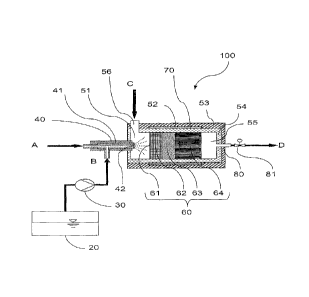
Fig. 1 shows a first ammonia gas generator (100) according to the present
invention. The
generator (100) is in the form of a cylinder and comprises an injection device
(40), a
catalyst unit (70) and an outlet (80) for the ammonia gas formed. The catalyst
unit (70)
consists of a multi-part hydrolysis catalyst (60), a mixing chamber (51) and
an outlet
chamber (55). In the operating state, the ammonia precursor solution (B) is
sprayed out of
a reservoir container (20) via a metering pump (30) together with an
atomisation air
stream (A) via a two-substance nozzle (41) having a nozzle opening (42) into
the mixing
chamber (51) of the ammonia gas generator (100) at a defined spray angle, and
distributed into fine droplets. A hot transport gas stream (C) is additionally
introduced into
the mixing chamber (51) tangentially via the inlet (56), generating an eddy
mist flow
comprising the droplets, which is passed axially in the direction of the
hydrolysis catalyst
(60) onto the hydrolysis catalyst end face (61). The catalyst (60) is
configured in such a
way that the first segment (62) is in the form of an electrically heatable
metal carrier
comprising a hydrolysis coating. This is followed by an unheated metal carrier
catalyst
(63), likewise comprising a hydrolysis coating and an unheated catalyst (64)
comprising a
hydrolysis coating configured as a mixer structure for better radial
distribution. The
generated ammonia gas (D) exits the generator (100) together with the hot
carrier gas
stream via the outlet chamber (55) comprising the outlet (80) and the valve
(81). The
generator may additionally be heated by a jacket heater (52) around the
housing (54) of
the catalyst unit. Apart from the head region in which the injection device
(40) is located,
the ammonia gas generator (100) is enclosed in a thermal insulation (53) of
microporous
cladding material.
Fig. 2 shows a schematic material flow of an exhaust treatment on a combustion
engine
(10). In this context, the exhaust from the combustion engine (10) is passed
through a
charging unit (11) and in a counter flow incoming air (E) for the internal
combustion
engine is compressed. The exhaust (F) is guided over an oxidation catalyst
(12), so as to
achieve a higher NO2 concentration in relation to NO. The ammonia-containing
gas
stream (D) from the ammonia gas generator (100) can be supplied and mixed in
both
upstream and downstream from a particle filter (13). In this context, an
additional gas
mixer (14) in the form of a static mixer or for example a Venturi mixer may be
used. The
NO, is reduced at the SCR catalyst (15) by means of the reducing agent NH3 at
an SCR
CA 02840760 2013-12-30
22
catalyst (SCR = selective catalytic reduction). In this context, the ammonia
gas generator
may be operated using separate carrier gas or else using a partial exhaust
stream.
Fig. 3 is a detailed view of the mixing chamber (51) in the region of the
tangential
carrier gas stream supply. The housing (54) of the catalyst unit is enclosed
in a
thermal insulation (53) of microporous cladding material in the region of the
mixing chamber (51). The tangential supply of the carrier gas (C) is provided
in
the head region of the ammonia gas generator or in the head region of the
mixing chamber (51), at the level of the nozzle opening (42) of the nozzle
(41). In
this context, the inlet (56) for the carrier gas stream (C) is configured in
such a
way that the gas stream is introduced as shallowly as possible against the
wall
(54) of the mixing chamber, in such a way that a downwardly directed eddy
current in the generator in the direction of the catalyst and thus a
tangential
carrier gas stream inside the catalyst unit sets in.
Practical example 1:
The construction basically corresponds to the ammonia gas generator shown in
Fig. 1. The
ammonia generator is configured for a metered amount of 10 ¨ 100 g/h NH3 and
is in the
form of a cylindrical tubular reactor. A two-substance nozzle from Schlick,
model 970 (0.3
mm), having a variable air cap and coated with amorphous Si, is arranged
centrally in the
head region. The ammonia precursor substance is metered in at room temperature
through
this nozzle and atomised in a full cone. The spray angle a is 30 . The
distance of the
nozzle opening from the catalyst end face is 100 mm and the spray head cone
diameter is
54 mm.
In this context, the liquid is entrained, by means of a pressurised air stream
(0.5 ¨ 2 bar) of
approximately 0.8 kg/h which is passed through the nozzle, and atomised. The
Sauter
mean diameter of the resulting droplets below the nozzle is <25 pm. There is a
uniform
radial distribution of the solution of the ammonia precursor substance over
the reactor
cross-section in the hot transport gas stream upstream from the hydrolysis
catalyst in a
mixing chamber, without these touching the reactor wall in the process, which
could lead to
depositions. In the mixing chamber drops are already evaporating in such a way
that upon
incidence on the catalyst end face the droplet diameter is reduced by up to 20
%. As a
result of the droplets which are still present, cooling of approximately 120 ¨
150 C occurs
at the catalyst end face. Therefore, the reactor is configured in such a way
that the amount
of heat supplied with the hot carrier gas stream, the integrated heatable
hydrolysis catalyst
CA 02840760 2013-12-30
23
and further supplies of energy introduce sufficient energy that for the amount
of solution
metered in there is no cooling to below approximately 300 C. In this context,
the metered
amount of 50 ¨ 280 g/h is controlled by means of a Bosch PWM valve. The
pressure for
conveying the liquid is generated from a pressurised air line in a reservoir
container by
overpressure, and therefore no additional conveyor pump is required.
A hot carrier gas stream (transport gas stream) of approximately 1 ¨ 5 kg/h is
likewise
introduced tangentially in the head region of the ammonia gas generator in
such a way
that it is laid in a mist stream around the reactor wall and is passed through
the mixing
chamber in a spiral shape. As a result, sprayed droplets are further prevented
from
coming into contact with the reactor wall. The diameter of the mixing chamber
in the head
region of the reactor is 70 mm. The length of the mixing chamber is 110 mm.
The mixing
chamber is additionally heated from the outside via an electric resistance
heating casing
(heating time max. 1 min.) ¨ model Hewit 0.8 ¨ 1 kW, 150 ¨200 mm. The
temperature is
regulated in connection with temperature sensors (type K) which are arranged
in and
downstream from the catalyst and on the catalyst end face. All of the outer
surfaces of the
reactor are enclosed by Microtherm superG insulation. In this context, the
Microtherm
superG filling is embedded between glass fibre meshing which is wound around
the
reactor. Only the head region in which the solution is injected is
uninsulated, for better
heat dissipation. The surfaces in the mixing chamber are coated with
catalytically active
T102washcoats (anatase structure).
A heatable metal carrier catalyst of 55 mm diameter and 400 cpsi (Emitec
Emicat,
maximum power 1.5 kW, volume approximately 170 ml) is flange-mounted
downstream
from the mixing chamber. Said catalyst is in the form of a hydrolysis
catalyst, likewise
coated with catalytically active TiO2 (anatase, washcoat approximately 100
g/I, from
Interkat/Sadchemie), and is regulated in such a way that the temperature at
the catalyst
end face is between 300 and 400 C. In this context, only enough energy is
supplied to
compensate the cooling resulting from the evaporation of the droplets. To
achieve a
space velocity of up to at least 7000 1/h, a further hydrolysis catalyst of
400 cpsi is
connected downstream, resulting in a total catalyst volume of approximately
330 ml.
The ammonia generated at the hot hydrolysis catalyst flows freely via the
outlet chamber in
the foot region, centrally from an outlet opening out of the reactor end
piece. In this context,
the outlet region is preferably shaped conically, so as to prevent eddy
formation at edges
and thus depositions of possible residues. The gas mixture from the ammonia
gas
CA 02840760 2013-12-30
24
generator is preferably supplied to the motor exhaust stream upstream from the
SCR
catalyst at a temperature > 80 C to prevent ammonium carbonate depositions,
and
distributed homogeneously in this exhaust stream by way of a static mixer.
1.4301 (V2A, DIN X 5 CrNi 18-10) or alternatively 1.4401 (V4A, DIN X 2 CrNiMo
17-12-2),
1.4767, or other Fe Cr Al alloys typical of exhaust catalysts are used as the
material for all
of the metal components.
This generator was operated with a 60 % guanidium formate solution and with a
32.5 %
aqueous urea solution as well as with mixtures of the two. In this context,
the results for
these ammonia precursor solutions are approximately identical ( 1 %).
The operating parameters which should be adhered to during operation of the
ammonia
gas generator are specified in the following.
Table 1: overview of further operating parameters
Name Formula Units Range
from average to
Metering mass flow of the solution of
the ammonia precursor substance MRed [g/h] 50 150 280
per hour
Carrier gas mass flow MAbg [kg/hi 1 5 10
Atomisation air mass flow hiDLise [kg/h} 0.14 0.71 1.43
Heating energy EHeiz [J/s] = [W] 0 70 150
Catalyst end face temperature Tem [ C] 280 350 500
Catalyst outlet temperature Taus 1 C] 250 320 450
Catalyst space velocity RG [1/h] 5000 15000 30000
Metering pressure of the liquid PRed [bar] 1 2 8
Catalyst end face loading per mRed
(g/(h*cm2)] 0.53 1.59 3.45
hour Akat
CA 02840760 2013-12-30
Specific enthalpy flow FITG/M Red Ek-lik91 8000 16000 25000
By means of the inlet which generates a tangential carrier gas stream with
respect
to the solution injected into the mixing chamber, and the separate
introduction of
the solution and the carrier gas, depositions can be prevented from forming on
the
catalyst end face or the mixing chamber wall over a period of > 100 hours.
Thus,
the generator and the method are to be classified as low maintenance.
In the following, the effect of the end face loading and the specific enthalpy
flow on
the continuous generation of ammonia is specified, the ammonia gas generator
used in example 1 being used. This generator was operated with a 60 %
guanidium
formate solution and with a 32.5 % aqueous urea solution as well as with
mixtures of
the two. In this context, the results for these ammonia precursor solutions
are
approximately identical ( 1 %). The formation of ammonia according to the end
face
loading is shown in Fig. 4.
Table 2: method according to the end face loading
V1 V2 V3 V4 V5
Distance from nozzle opening to catalyst end face
100 100 100 100 100
[mm]
Spray cone diameter [mm] 54 54 54 54 54
Metering mass flow of the solution of the ammonia
50 160 280 4 400
precursor substance per hour [g/h]
Catalyst end face loading per hour [g/(h*cm2)] 2.1 7.0 12.0 0.17
17.5
Specific enthalpy flow 8000 12000 16000 16000 16000
95 95
Ammonia formation level AG [%] .95`)/0 .95%
<90%
Depositions on catalyst end face none none none none yes
Depositions on the mixing wall chamber none none none none none
CA 02840760 2013-12-30
26
By setting the catalyst end face loading to at least 0.17 g/(h*cm2) (cf. V4),
a
method can be provided in which no depositions are formed over a period of >
100 h. If the end face loading is 2.1 g/(h*cm2) or 7.0 g/(h*cm2) or 12.0
g/(h*cm2)
over a period of > 100 h, no depositions are observed, by means of which a
continuous method is ensured. If the end face loading is set to a value of
17.5
g/(h*cm2) (cf. V5), depositions on the catalyst end face can be observed. A
continuous method is thus no longer possible.
Table 3: method according to the specific enthalpy flow
V1 V2 V3 V4 V5
Distance from nozzle opening to
100 100 10 100 100
catalyst end face [mm]
0
Spray cone diameter [mm] 54 54 54 54 54
Metering mass flow of the solution of
160 160 16 160 160
the ammonia precursor substance
0
per hour [g/h]
Catalyst end face loading per hour
7.0 7.0 7.0 7.0 7.0
[g/(h*
cm211
Specific enthalpy flow [kJ/kg] 8000 1200 16000 2000
2000
0 0
Ammonia formation level AG [%] a95% 95')/o -95% <90%
a95%
Depositions on catalyst end face none none none yes none
Depositions on the mixing wall none none none yes none
chamber
By setting the specific enthalpy to at least 8000 kJ/kg (cf. V1, V2, V3 and
V5) a
method can be provided in which no depositions are formed over a period of >
100 h, by means of which a continuous method can be provided. If the specific
enthalpy is adjusted to 2000 kJ/kg (cf. V4), depositions on the mixing wall
CA 02840760 2013-12-30
27
chamber and the catalyst end face can be observed. The formation of ammonia
according to the specific enthalpy flow is shown in Fig. 5.
Practical example 2:
In practical example 2, the reactor is configured in such a way that the
reactor is
additionally heated in part as a result of counter flow heat exchange by the
supplied hot transport gas stream. In this context, the transport gas stream
is
initially passed below the reactor head, via a double casing, counter to the
flow
direction in the inside of the double casing, to the reactor wall, and flows
around
said wall on the way to the reactor head. At the reactor head, the primary
flow
from the reactor double casing enters the reactor interior from the reactor
double
casing via a plurality of holes or alternatively via an annular gap in the
region of
the nozzle at the reactor head. In addition, an electrical resistance heater
may be
located in the double casing.
Practical example 3:
In practical example 3, the reactor is configured in such a way that the
reactor is heated
from the outside by heat exchange with hot components of a combustion engine
or of a
separate burner for exhaust heating or by hot gas flows, rather than by means
of an
electrical resistance heater. In this context, the heat can also be
transported to the reactor
via a heating tube over some distance.
Practical example 4:
In practical example 4, the reactor is configured in such a way that heat is
supplied directly
in the interior of the reactor by means of an electrically heatable Emikat
catalyst from
Emitec, instead of the reactor being heated from the outside. Alternatively
heat can be
generated in the reactor by glow plugs, model Champion (60 W, 11 V).
Practical example 5:
With preheating of the liquid solution of the ammonia precursor substance ¨
when an injector
having critical superheating (flash evaporator) is used.