Note: Descriptions are shown in the official language in which they were submitted.
= = CA 02840915 2014-01-03
=
Method and linear device for handling articles
Description
The invention relates to a method for handling (flat)
articles, in particular hygiene products such as
diapers, napkins or the like, wherein the articles are
supplied on a first feed conveyor and are removed as a
compressed group of articles on a removal conveyor, as
claimed in the preamble of claim 1. In addition, the
invention relates to a corresponding device, as claimed
in the preamble of claim 4.
Different variants of such devices and methods are
known from practice. A disadvantage of the
corresponding devices and methods, however, is the
capacity of previous concepts which on the whole is no
longer sufficient.
Proceeding from here, the object of the invention is to
develop further known devices and methods, in
particular with regard to greater capacity.
A method with the features of claim 1 is proposed to
achieve said object. It is accordingly provided that
the feed conveyor and the removal conveyor are
continuously driven and a group of articles is
transferred from the continuously driven feed conveyor
to a continuously driven compressing device in which
the group of articles is compressed, and that the
compressed group of articles is transferred from the
, CA 02840915 2014-01-03
- 2 -
compressing device to the continuously driven removal
conveyor.
In addition, it is provided that the compressing device
has a continuously driven compressing conveyor, in the
region of which the group of articles is compressed
during the continuous conveying, wherein the
compressing conveyor has lateral guides which are
located opposite one another, the articles being
conveyed through between said lateral guides, wherein
the distance between the opposite guides is reduced
over the length of the compressing conveyor for
continuously compressing the group of articles when
they are being conveyed on the compressing conveyor.
A characteristic consists in that the compressing
conveyor has an inlet region which faces the feed
conveyor and an outlet region which faces the removal
conveyor, wherein the inlet region and/or the outlet
region are moved together with the group of articles on
the feed conveyor or to the delivery position on the
removal conveyor to transfer the articles between the
conveyors during the continuous conveying. The
advantage of said solution is that, in particular, the
articles are able to be transferred during the
continuous running of the feed conveyor and of the
removal conveyor.
As claimed in a preferred further development, it is
provided that the inlet region and the outlet region of
the compressing conveyor are moved independently of one
another.
In addition, the articles are preferably arranged in
compartments which are formed on the feed conveyor and
are pushed out of the laterally open compartments into
the inlet region of the compressing conveyor by means
of a pushing device, wherein the compressing conveyor
CA 02840915 2014-01-03
=
- 3 -
extends at an angle, in particular transversely, with
respect to the feed conveyor, and in that the
compressed group of articles is transferred in the
outlet region of the compressing conveyor into a
compartment which is formed on the removal conveyor,
wherein the removal conveyor extends at an angle, in
particular transversely, with respect to the
compressing conveyor and preferably parallel to the
feed conveyor.
A device for achieving the object mentioned in the
introduction has the features of claim 4. It is
correspondingly provided that the feed conveyor and the
removal conveyor are set up for continuously conveying
the articles or a compressed group produced of articles
and that the compressing device, which is arranged
between the feed conveyor and the removal conveyor, is
set up for the continuous compressing of groups of
articles.
In addition, it is provided that the compressing device
has a continuously operating compressing conveyor,
having lateral guides which are located opposite one
another and are arranged converging in the direction of
the removal conveyor and wherein the compressing
conveyor has an inlet region which faces the feed
conveyor and an outlet region which faces the removal
conveyor, wherein the inlet region and/or the outlet
region are movable together with the group of articles
on the feed conveyor or to the delivery position on the
removal conveyor for transferring the articles between
the conveyors during the continuous conveyance.
In a preferred further development of the device as
claimed in the invention, it can be provided that the
articles rest on a conveyor path in the region of the
compressing conveyor and are movable in the direction
of the removal conveyor by conveying means of the
CA 02840915 2014-01-03
=
- 4 -
compressing conveyor, wherein the conveying means are
formed by conveying members which are directed
transversely with respect to the conveying direction
and are arranged at least in each case at the rear
behind a group of articles and wherein the group of
articles is preferably supported at the front by a
further conveying member.
In a preferred exemplary embodiment, it can be provided
that the conveying members are formed by transverse
struts which are guided through recesses in the lateral
guides of the compressing conveyor, and that the
distance between the rear and front conveying members
can preferably be modified according to the dimensions
of the articles to be conveyed.
A further characteristic can consist in that lateral
guides of the inlet region and/or of the outlet region
are arranged in each case substantially parallel to one
another and are modifiable with regard to their
respective distance from one another, preferably
individually, and in that the lateral guides are
preferably arranged parallel to entrainment means of
the feed conveyor and/or of the removal conveyor for
forming laterally open compartments for several
articles.
In addition, it can be significant for the lateral
guides to be realized so as to be deformable in each
case between the inlet region and the outlet region, in
particular as a result of the articulated connection of
part guides to one another and/or to the inlet region
and/or to the outlet region.
A preferred exemplary embodiment is described in detail
below by way of the drawing, in which:
. CA 02840915 2014-01-03
- 5 -
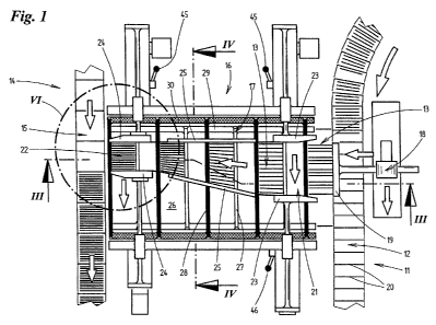
fig. 1 shows a top view of a device for handling
articles, when the articles are supplied from
a first conveyor (feed conveyor),
fig. 2 shows the device according to fig. 1 when the
compressed articles are transferred onto a
second conveyor (removal conveyor),
fig. 3 shows a vertical section through the device
along the line of intersection IIiIii in
fig. 1,
fig. 4 shows a vertical section through the device
along the line of intersection IV-IV in fig.
1,
fig. 5 shows a detail V of the device in an enlarged
partial representation, according to the
marking in fig. 3, and
fig. 6 shows a detail VI of the device in an
enlarged partial representation, according to
the marking in fig. 1.
The invention is described below by way of a device for
grouping articles 10. The articles 10 can be (packaged)
hygiene products such as diapers, napkins or cleansing
cloths. In the present case the articles 10 are flat in
form.
The articles 10 are conveyed on a continuously driven
feed conveyor 11. Compartments 12, in which several
articles 10 can be arranged, are formed on the feed
conveyor 11. In the present case, the contents of
several compartments 12 form a group 13 of articles 10
to be packaged. As an alternative to this, it is also
conceivable for the contents of just one compartment 12
of the feed conveyor 11 to form the group 13.
In the exemplary embodiment shown, the articles 10 are
arranged standing upright in the compartments 12. A
sealing position of the articles 10 in the compartments
12 is conceivable insofar as said compartments are
. CA 02840915 2014-01-03
- 6 -
completely filled. The articles 10 preferably abut
against one another in the compartments 12 with their
large-area (front and rear) sides. The articles 10
preferably rest on a top run of the feed conveyor 11 or
of a conveyor path.
A removal conveyor 14 which is continuously driven as
the feed conveyor 11 is additionally provided.
Compartments 15 are also formed on the removal conveyor
14 for receiving compressed articles 10. It is provided
that a compartment 15 includes in each case the number
of articles 10 corresponding to the contents of a pack.
As an alternative to this, it is naturally also
conceivable for the contents of several compartments 15
to form the contents of the pack.
The articles 10 are also arranged standing upright in
the compartments 15 on the removal conveyor 14. On
account of the compressing of the articles 10, they
abut against one another in a sealing position by way
of their large-surface (front and rear) sides.
A compressing device 16 for compressing a group 13 of
articles 10 is arranged between the feed conveyor 11
and the removal conveyor 14. To this end, during the
continuous conveying, the group 13 is transferred from
the feed conveyor 11 to the compressing device 16 and,
after compressing, is transferred into a compartment 15
on the removal conveyor 14 which is also driven
continuously at the same time.
In the present case, the compressing device 15 has a
compressing conveyor 17 which conveys the group 13 of
articles 10 between the feed conveyor 11 and the
removal conveyor 14 and at the same time compresses
them. The compressing conveyor 17 extends at an angle,
preferably transversely, between the feed conveyor 11
and the removal conveyor 14, which extend parallel to
. CA 02840915 2014-01-03
- 7 -
one another in the region of the compressing conveyor
17. The feed conveyor 11 and the removal conveyor 14
convey the articles 10, in the present case, in the
same direction. It is conceivable for the feed conveyor
11 and the removal conveyor 14 to convey the articles
in different, in particular opposite, directions.
To transfer a group 13 of articles 10 from the feed
conveyor 11 to the compressing conveyor 17, a pushing
10 device 18 is provided by way of which the group 13 is
able to be pushed out of the compartment 12 at an
angle, in particular transversely, with respect to the
direction of transport on the feed conveyor 11, and
supplied to the compressing conveyor 17. For this
purpose, the pushing device 18 has a slide 19 which is
moved laterally to abut against an upright pack edge or
surface of the articles 10 and which supplies the
articles 10 to the compressing conveyor 17.
The slide 19 is set up together with the articles 10 to
be moved in the conveying direction of the feed
conveyor 11 in order to make it possible for the
articles 10 to be pushed away during the continuous
conveying. To this end, the slide 19 is mounted
laterally of the feed conveyor 11 in such a manner that
it is movable parallel to said feed conveyor in and in
opposition to the conveying direction of the same. In
addition, the slide 19 is mounted so as to be
displaceable transversely with respect to the conveying
direction in order to push away the articles 10. In
addition, the slide 19 is mounted so as to be pivotable
in order to be able to be moved back into a start
position once the articles 10 have been pushed away
(fig. 3). The pivot axis of the slide 19, in this case,
extends parallel to the longitudinal axis of the feed
conveyor 11.
. CA 02840915 2014-01-03
- 8 -
The compartments 12 on the feed conveyor 11 are defined
transversely with respect to the conveying direction by
means of entrainment means 20. The entrainment means 20
have a smaller vertical extension than the articles 10
such that the articles 10 project above the entrainment
means 20 and thus can be intercepted laterally by the
slide 19 in said region.
The compressing conveyor 17 has an inlet region 21
which faces the feed conveyor 11 and an outlet region
22 which faces the removal conveyor 14. The inlet
region 21 and the outlet region 22 have in each case
substantially parallel, lateral guides 23, 24 for a
group 13 of articles 10. The lateral guides 23, 24, are
in each case aligned parallel to the entrainment means
of the feed conveyor 11 and the removal conveyor 14.
Lateral guides 25, which extend longitudinally of the
conveying path of the group 13 of articles 10, are
arranged in each case between the lateral guides 23, 24
in the inlet region 21 and the outlet region 22. The
lateral guides 23, 24, 25 which are adjacent in each
case are connected together in an articulated manner.
To this end, the guides 23, 24 25 can be connected
together by means of corresponding joints or by means
of articulated intermediate pieces 47 (fig. 6).
Coming from the feed conveyor 11, the group 13 of
articles 10 is pushed by the pushing device 18 between
the lateral guides 23 of the inlet region 21. The end
regions of the lateral guides 23 which face the feed
conveyor 11, in this case, are realized in a slightly
diverging manner in order to facilitate pushing the
group 11 in between the lateral guides 23. The distance
between each of the lateral guides 23, in this case,
corresponds to the width (size) of the non-compressed
group 13 of articles 10.
= CA 02840915 2014-01-03
=
- 9 -
The distance between the lateral guides 24 in the
outlet region 22 is smaller than the distance between
the lateral guides 23 and corresponds substantially to
the width of a compartment 12 on the removal conveyor
14. Where applicable, the distance can be somewhat
smaller than the corresponding width of a compartment
12.
The lateral guides 25, which extend between the lateral
guides 23, 24 of the inlet region 21 and of the outlet
region 22, extend converging toward one another such
that the channel formed between the lateral guides 23,
24, 25 for the articles 10 tapers from the inlet region
21 to the outlet region 22. The group 11 is
correspondingly compressed as a result of conveying the
group 11 of articles 10 along the lateral guides 23,
24, 25. The articles 10, in this case, are conveyed in
a continuous manner as on the feed conveyor 11 and the
removal conveyor 14.
During the continuous conveying of the articles 10 on
the compressing conveyor 17, the articles 10 rest on a
conveyor path 26 which extends between the feed
conveyor 11 and the removal conveyor 14. The group 13
of articles 10 is moved in a continuous manner between
the feed conveyor 11 and the removal conveyor 14 by a
conveying means. In the present case, the conveying
means has, as conveying members, transverse struts 27,
which are aligned transversely with respect to the
conveying direction of the articles 10, abut against a
group 13 at the rear in the conveying direction and
push said group over the conveying path 26. Further
transverse struts 28 are provided for abutting against
a group 13 at the front. The transverse struts 27, 28
are arranged following one another in an alternating
manner.
. CA 02840915 2014-01-03
=
- 10 -
The two groups of transverse struts 27, 28 are driven
in each case by means of conveyor chains 29, 30. The
conveyor chains 29, 30 extend in each case on both
sides of the conveyor path 26 and are connected to the
transverse struts 27 or 28. The inner conveyor chain 29
serves for driving the transverse struts 27, whereas
the outer conveyor chain 30 serves for driving the
transverse struts 28. The conveyor chains 29, 30 are
guided by means of guide rollers in such a manner that
the transverse struts 27, 28 are guided along at a
spacing above the conveyor path 26 for conveying the
articles 10. A separate drive shaft 31, 32 for the
conveyor chain 29, 30 is provided in each case below
the conveyor path 26. Only the drive shaft 32 for the
outer conveyor chain 30 is driven by a drive 35. By
coupling the two drive shafts 31, 32 by means of a
drive belt 33, the two drive shafts 31, 32 are moved by
means of the drive 34.
Several transverse struts 27, 28 are distributed in
each case at regular spacings over the circumference of
the conveyor chains 29, 30. In this way, several groups
13 of articles 10 can be conveyed at the same time on
the compressing conveyor 17. The distance between the
transverse struts 27, 28 of the same conveyor chain 29,
is fixedly predetermined and cannot be modified. The
distance between the transverse struts 27, 28 of the
two different conveyor chains 29, 30, in contrast, can
be modified. For this purpose, the relative position of
30 the two conveyor chains 29, 30 can be modified with
respect to one another and fixed by means of a latching
device, in particular a latching bolt 35. In this way,
the distance between consecutive transverse struts 27,
28 can be adapted with respect to one another,
depending on the length of the articles 10 to be
handled in the conveying direction of the compressing
conveyor 17. Slot-like openings 38, through which the
CA 02840915 2014-01-03
- 11 -
transverse struts 27, 28 extend, are realized in the
lateral guides 23, 24, 25.
A characteristic consists in that the inlet region 21
and the outlet region 22 are movable in each case
preferably independently of one another, corresponding
to the movement of the feed conveyor 11 or of the
removal conveyor 14.
For this purpose, both the inlet region 21 and the
outlet region 22 are movable transversely with respect
to the conveying direction of the compressing conveyor
17 and are certainly movable independently of one
another. To this end, the inlet region fl is mounted so
as to be displaceable along a corresponding first
transverse axis 36 and the outlet region 22 is mounted
so as to be displaceable along a corresponding second
transverse axis 37. The transverse axes 36, 37 extend
parallel to the feed conveyor 11 or to the removal
conveyor 14 and are displaceable in the axial direction
by means of corresponding servo drives 48.
In addition, it is provided that the distance between
the lateral guides 23, 24 of the inlet region 21 and of
the outlet region 22 is adjustable. For this purpose,
the lateral guides 23, 24 are arranged in each case on
support devices 39, 40 which are adjustable with
respect to one another and which are displaceable
together by moving the transverse axis. Each support
device 39, 40 has two support arms 41, 42 which are
connected together and, at the end of each of the
support devices, supports part of the lateral guides
23, 24 above and below the openings 38 for the
transverse struts 27, 28. The interconnected support
arms 41, 42 are displaceable with respect to one
another along clamping rails 43, 44 which are
associated with the transverse axes 36, 37. The
relative position of the support devices 39, 40 can be
CA 02840915 2014-01-03
- 12 -
fixed with regard to the clamping rails 43, 44,
preferably by means of clamping levers 45, 46.
The device described thus far operates as follows:
The articles 10 are conveyed into the compartments 12
of the feed conveyor 11 by means of a device (not
shown), the articles standing upright in the
compartments 12 and being arranged transversely with
respect to the conveying direction. In the region of
the pushing device 18, a group 13 of articles 10 is
intercepted by the slide 19 and pushed into the inlet
region 21 of the connecting compressing conveyor 17
during the continuous running of the feed conveyor 11.
In this case, the inlet region is moved correspondingly
to the movement of the group 13 together with the ram
19 such that the group 13 is pushed away during the
continuous movement of the articles 10 or of the group
13.
The group 13, which is pushed in between the lateral
guides 23 of the inlet region 21, is intercepted at the
rear by a transverse strut 27 and pushed along the
conveyor path 26. The group is guided at the front by a
transverse strut 28. Whilst the group 13 is being
conveyed in this manner, the group 13 is compressed by
the converging lateral guides 25. As soon as the group
13 arrives in the outlet region 22, the compressing is
terminated and the dimensions of the group 13
correspond to the dimension of a compartment 15 on the
connecting removal conveyor 14. The compressed group 13
is pushed off into a compartment 15 of the removal
conveyor 14 by means of the rear transverse struts 27.
In this case, the outlet region is moved
correspondingly to the continuously driven removal
conveyor 14 such that the group 13 is able to be
transferred during the continuous operation of the
, CA 02840915 2014-01-03
- 13 -
device. Afterwards, the group 13 can be transferred
into a unit packaging.
Several groups 13 are able to be compressed one after
another at the same time on the compressing conveyor
17. Both the inlet region 21 and the outlet region 22
are moved independently of one another, corresponding
to the movement of the compartments 12, 15 on the feed
conveyor 11 or the removal conveyor 14. As a result of
the articulated connection between the lateral guides
23, 24, 25, the conveying channel can be adapted to the
changing position of the inlet region 21 and of the
outlet region 22. In addition, it is possible to
provide length compensation for the lateral guides 23,
24, 25, as shown, for example, in fig. 6. In this case,
a support arm 41 (42) is fastened on a lateral guide 24
with lateral play.
To adapt to the conveying of articles 10 of other
sizes, the adjusting of the distance between the
lateral guides 23, 24 is provided on the one hand. In
this way, the device can be adapted to a different
width of the articles 10 transversely with respect to
the conveying direction. On the other hand, it is
possible to modify the distance between the transverse
struts 27, 28 with respect to one another. In this way,
the device can be adapted to a different length of the
articles 10 in the conveying direction.
, CA 02840915 2014-01-03
- 14 -
List of references
Article
11 Feed conveyor
12 Compartment
13 Group
14 Removal conveyor
Compartment
16 Compressing device
17 Compressing conveyor
18 Pushing device
19 Slide
Entrainment means
21 Inlet region
22 Outlet region
23 Guide (inlet region)
24 Guide (outlet region)
Guide
26 Conveyor path
27 Transverse strut
28 Transverse strut
29 Conveyor chain
Conveyor chain
31 Drive shaft
32 Drive shaft
33 Drive belt
34 Drive
Latching bolt
36 Transverse axis (inlet region)
37 Transverse axis (outlet region)
38 Opening
39 Support device
Support device
41 Support arm
42 Support arm
43 Clamping rail
44 Clamping rail
CA 02840915 2014-01-03
- 15 -
45 Clamping lever
46 Clamping lever
47 Intermediate piece
48 Servo drive