Note: Descriptions are shown in the official language in which they were submitted.
CA 02841171 2014-01-07
WO 2013/009720
PCT/US2012/045994
HIGH TEMPERATURE ENERGY STORAGE DEVICE
BACKGROUND OF THE INVENTION
1. Field of the Invention
[0001] The invention disclosed herein relates to energy storage cells, and in
particular to
techniques for providing an electric double-layer capacitor that is operable
at high
temperatures.
2. Description of the Related Art
[0002] Energy storage cells arc ubiquitous in our society. While most people
recognize an
energy storage cell simply as a "battery," other types of cells may be
included. For example,
recently, ultracapacitors have garnered much attention as a result of their
favorable
characteristics. In short, many types of energy storage cells are known and in
use today.
[0003] As a general rule, an energy storage cell includes an energy storage
media disposed
within a housing (such as a canister). While a metallic canister can provide
robust physical
protection for the cell, such a canister is typically both electrically and
thermally conductive
and can react with the energy storage cell. Typically, such reactions increase
in rate as
ambient temperature increases. The electrochemical or other properties of many
canisters
can cause poor initial performance and lead to premature degradation of the
energy storage
cell, especially at elevated temperatures.
100041 In fact, a variety of factors work to degrade performance of energy
storage systems at
elevated temperatures. Thus, what are needed are methods and apparatus for
improving
performance of an electric double-layer capacitor at elevated temperatures.
Preferably, the
methods and apparatus result in improved performance at a minimal cost.
BRIEF SUMMARY OF THE INVENTION
[0005] In one embodiment, an ultracapacitor is disclosed. The ultracapacitor
includes an
energy storage cell immersed in an electrolyte and disposed within an
hermetically sealed
housing, the cell electrically coupled to a positive contact and a negative
contact, wherein the
ultracapacitor is configured to output electrical energy at a temperature
within a temperature.
range between about 80 degrees Celsius to about 210 degrees Celsius.
- I -
CA 02841171 2014-01-07
WO 2013/009720
PCMJS2012/045994
[0006] In another embodiment, a method for fabricating an ultracapacitor is
provided. The
method includes disposing an energy storage cell including energy storage
media within a
housing; and constructing the ultracapacitor to operate within a temperature
range between
about 80 degrees Celsius to about 210 degrees Celsius.
[0007] In yet another embodiment, a method for fabricating an ultracapacitor
is provided.
The method includes disposing an energy storage cell including energy storage
media within
a housing; and filling the housing with electrolyte adapted for operation
within a temperature
range between about 80 degrees Celsius to about 210 degrees Celsius.
[0008] In a further embodiment, an ultracapacitor is disclosed. The
ultracapacitor includes
an energy storage cell wetted with an electrolyte and disposed within a
housing, wherein a
level of moisture within the housing is no greater than about 1,000 parts per
million (ppm) by
combined weight of the storage cell and electrolyte.
[0009] In yet a further embodiment, an ultracapacitor is disclosed. The
ultracapacitor
includes an energy storage cell wetted with an electrolyte and disposed within
a housing,
wherein a level of halide impurities within the housing is no greater than
1,000 parts per
million by combined weight of the storage cell and electrolyte.
[0010] In another embodiment, a method for characterizing a contaminant within
an
ultracapacitor is provided. The method includes breaching a housing of the
ultracapacitor to
access contents thereof; sampling the contents; and analyzing the sample.
[0011] In one embodiment, an ultracapacitor is disclosed. The ultracapacitor
exhibits a
volumetric leakage ,current (mA/cc) that is less than about 10mA/cc while held
at a
substantially constant temperature within a range of between about 100 degrees
Celsius and
about 150 degrees Celsius.
[0012] In one embodiment, an ultracapacitor is disclosed. The ultracapacitor
exhibits a
volumetric leakage current of less than about 10mA/cc while held at a
substantially constant
= temperature within a temperature range of between about 140 degrees
Celsius and 180
degrees Celsius.
[0013] In one embodiment, an ultracapacitor -is disclosed. The ultracapacitor
exhibits a
volumetric leakage current of less than about 10mA/cc while held at a
substantially constant
temperature within a temperature range of between about 170 degrees Celsius
and 210
degrees Celsius.
- 2 -
CA 02841171 2014-01-07
WO 2013/009720
PCT/US2012/045994
[0014] In another embodiment, a method for providing a high temperature
rechargeable
energy storage device is disclosed. The method includes selecting a high
temperature
rechargeable energy storage device (HTRESD) that exhibits initial peak power
density
between 0.01 W/liter and 100 kW/liter and a lifetime of at least 20 hours when
exposed to an
ambient temperature ma temperature range from about 80 degrees Celsius to
about 210
degrees Celsius; and providing the storage device.
[0015] In another embodiment, a method for using a high temperature
rechargeable energy
storage device is disclosed. The method includes obtaining an HTRESD and; at
least one of
cycling the HTRESD by alternatively charging and discharging the HTRESD at
least twice
over a duration of 20 hours, and maintaining a voltage across the HTRESD for
20 hours, such
that the HTRESD exhibits a peak power density between 0.005 W/liter and 75
kW/liter after
20 hours when operated at an ambient temperature that is in a temperature
range of between
about 80 degrees Celsius to about 210 degrees Celsius.
[0016] In another embodiment, a method for using a high temperature
rechargeable energy
storage device is disclosed. The method includes obtaining an
ultracapacitor and;
maintaining a voltage across the ultracapacitor, such that the ultracapacitor
will exhibit a peak
. power density of between about 0.005 W/liter and about 75 kW/liter after 20
hours, wherein
the ultracapacitor is exposed to an ambient temperature in a temperature range
from about 80
degrees Celsius to about 210 degrees Celsius during the maintaining.
[0017] In another embodiment, a method for using an ultracapacitor is
disclosed. The
method includes obtaining an ultracapacitor that has an electrolyte and two
electrodes, each
of the electrodes in electrical communication with a current collector, and
separated from the
other by a separator; wherein one of charging and discharging the
ultracapacitor provides for
an initial combination of peak power and energy densities in a range from
about 0.1 Wh-kW /
liter2 to about 100 Wh-kW / liter2, wherein said combination is mathematically
a product of
the peak power density and the energy density of the ultracapacitor; and
wherein the
ultracapacitor exhibits a durability period of at least 20 hours when exposed
to an ambient
temperature in a temperature range from about 80 degrees Celsius to about 210
degrees
Celsius, wherein the durability is indicated by a decrease in peak power
density of no more
than about 50 percent over the period, and wherein the ultracapacitor is
configured to charged
and discharged at least twice.
- 3 -
81776703
[0017a] According to one embodiment of the present invention, there is
provided an
ultracapacitor comprising: an energy storage cell and an electrolyte within an
hermetically
sealed housing, the cell electrically coupled to a positive contact and a
negative contact,
wherein the ultracapacitor is configured to operate at a temperature within a
temperature range
between about 80 degrees Celsius to about 210 degrees Celsius.
10017b] According to another embodiment of the present invention, there is
provided an
ultracapacitor comprising: a positive electrode, a negative electrode, a
separator, and an
electrolyte within a hermetically sealed housing, wherein the ultracapacitor
has less than 200
ppm of halides and a water content of less than 100 ppm, wherein the
ultracapacitor exhibits
an equivalent series resistance (ESR) increase of less than about 300 percent
while held at a
constant voltage for at least 20 hours while held at a substantially constant
temperature within
a temperature range of between about 80 degrees Celsius and 210 degrees
Celsius, and
wherein: the ultracapacitor is configured to operate at a temperature between
80 degrees
Celsius and 210 degrees Celsius with a volumetric leakage current of less than
1,000 mAmp
per Liter, and/or the ultracapacitor exhibits a volumetric leakage current of
less than 10 mA/cc
while held at a substantially constant temperature between 100 degrees Celsius
and 150
degrees Celsius.
- 3a -
Date Recue/Date Received 2020-08-31
CA 02841171 2014-01-07
WO 2013/009720
PCMJS2012/045994
BRIEF DESCRIPTION OF THE DRAWINGS
[0018] The foregoing and other features and advantages of the invention are
apparent from
the following detailed description taken in conjunction with the accompanying
drawings in
which:
[0019] FIG. 1 illustrates aspects of an exemplary ultracapacitor;
[0020] FIG. 2 is a block diagram depicting a plurality of carbon nanotubes
(CNT) grown
onto a substrate;
[0021] FIG. 3 is a block diagram depicting deposition of a current collector
onto the CNT of
FIG. 3 to provide an electrode element;
= [0022] FIG. 4 is a block diagram depicting addition of transfer tape to
the electrode element
of FIG. 3;
[0023] FIG. 5 is a block diagram depicting the electrode element during a
transfer process;
[0024] FIG. 6 is a block diagram depicting the electrode element subsequent to
transfer;
[0025] FIG. 7 is a block diagram depicting an exemplary electrode fabricated
from a plurality
of the electrode elements;
[0026] FIG. 8 depicts embodiments of primary structures for cations that may
be included in
the exemplary ultracapacitor;
[0027] FIGS. 9 and 10 provide comparative data for the exemplary
ultracapacitor making use
of raw electrolyte and purified electrolyte, respectively;
[0028] FIG. 11 depicts an embodiment of a housing for the exemplary
ultracapacitor;
[0029] FIG. 12 illustrates an embodiment of a storage cell for the exemplary
capacitor;
[0030] FIG. 13 depicts a barrier disposed on an interior portion of a body of
the housing;
[0031] FIGS. 14A and 14B, collectively referred to herein as FIG. 14, depict
aspects of a cap
for the housing;
[0032] FIG. 15 depicts assembly of the ultracapacitor according to the
teachings herein;
[0033] FIGS. 16A and 16B, collectively referred to herein as FIG. 16, are
graphs depicting
performance for the ultracapacitor for an embodiment without a barrier and a
similar
embodiment that includes the barrier, respectively;
[0034] FIG. 17 depicts the barrier disposed about the storage cell as a
wrapper;
- 4 -
CA 02841171 2014-01-07
WO 2013/009720
PCT/US2012/045994
[0035] FIGS. 18A, 18B and 18C, collectively referred to herein as FIG. 18,
depict
embodiments of the cap that include multi-layered materials;
[0036] FIG. 19 is a cross-sectional view of an electrode assembly that
includes a glass-to-
metal seal;
[0037] FIG. 20 is a cross-sectional view of the electrode assembly of FIG. 19
installed in the
cap of FIG. 18B;
[0038] FIG. 21 depicts an arrangement of the energy storage cell in assembly;
[0039] FIGS. 22A, 22B and 22C, collectively referred to herein as FIG. 22,
depict
embodiments of an assembled energy storage cell;
[0040] FIG. 23 depicts incorporation of polymeric insulation into the
ultracapacitor;
[0041] FIGS. 24A, 24B and 24C, collectively referred to herein as FIG. 24,
depict aspects of
a template for another embodiment of the cap for the energy storage;
[0042] FIG. 25 is a perspective view of an electrode assembly that includes
hemispherically
shaped material;
[0043] FIG. 26 is a perspective view of a cap including the electrode assembly
of FIG. 25
installed in the template of FIG. 24;
[0044] FIG. 27 is a cross-sectional view of the cap of FIG. 26;
[0045] FIG. 28 depicts coupling of the electrode assembly with a terminal of a
storage cell;
[0046] FIG. 29 is a transparent isometric view of the energy storage cell
disposed in a
cylindrical housing;
[0047] FIG. 30 is a side view of the storage cell, showing the various layers
of one
embodiment;
[0048] FIG. 31 is an isometric view of a rolled up storage cell which includes
a reference
mark for placing a plurality of leads;
[0049] FIG. 32 is an isometric view of the storage cell of FIG. 31 once
unrolled;
[0050] FIG. 33 depicts the rolled up storage cell with the plurality of leads
included;
[0051] FIG. 34 depicts a Z-fold imparted into aligned leads (i.e., a terminal)
coupled to the
storage cell;
[0052] FIGS. 35 - 38 are graphs depicting performance of exemplary
ultracapacitors; and
- 5 -
CA 02841171 2014-01-07
WO 2013/009720
PCT/US2012/045994
[0053] FIGS. 39 - 43 are graphs depicting performance of exemplary
ultracapacitors at 210
degrees Celsius.
DETAILED DESCRIPTION OF THE INVENTION
[0054] Disclosed herein is a capacitor that provides users with improved
performance in a
wide range of temperatures. For example, the capacitor may be operable at
temperatures
ranging from about as low as minus 40 degrees Celsius to as high as about 210
degrees
Celsius. In some embodiments, the capacitor is operable temperatures ranging
from about 80
degrees Celsius to as high as about 210 degrees Celsius.
[0055] In general, the capacitor includes energy storage media that is adapted
for providing
high power density and high energy density when compared to prior art devices.
The
capacitor includes components that are configured for ensuring operation over
the
temperature range, and includes any one or more of a variety of forms of
electrolyte that are
likewise rated for the temperature range. The combination of construction,
energy storage
media and electrolyte result in capabilities to provide robust operation under
extreme
conditions. To provide some perspective, aspects of an exemplary embodiment
are now
introduced.
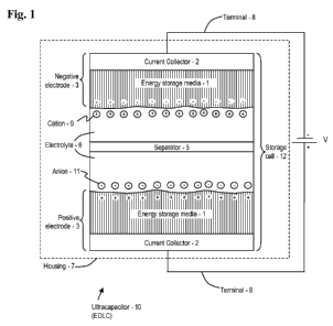
[0056] As shown in FIG. 1, an exemplary embodiment of a capacitor is shown. In
this case,
the capacitor is an "ultracapacitor 10." The exemplary ultracapacitor 10 is an
electric double-
layer capacitor (EDLC). The EDLC includes at least one pair of electrodes 3
(where the
electrodes 3 may be referred to as a negative electrode 3 and a positive
electrode 3, merely
for purposes of referencing herein). When assembled into the ultracapacitor
10, each of the
electrodes 3 presents a double layer of charge at an electrolyte interface. In
some
embodiments, a plurality of electrodes 3 is included (for example, in some
embodiments, at
least two pairs of electrodes 3 are included). However, for purposes of
discussion, only one
pair of electrodes 3 are shown. As a matter of convention herein, at least one
of the
electrodes 3 uses a carbon-based energy storage media I (as discussed further
herein) to
provide energy storage. However, for purposes of discussion herein, it is
generally assumed
that each of the electrodes includes the carbon-based energy storage media 1.
It should be
noted that an electrolytic capacitor differs from an ultracapacitor because
metallic electrode
differ greatly (at least an order of magnitude) in area.
[0057] Each of the electrodes 3 includes a respective current collector 2
(also referred to as a
"charge collector"). In some embodiments, the electrodes 3 are separated by a
separator 5.
- 6 -
CA 02841171 2014-01-07
WO 2013/009720
PC1'4182012/045994
In general, the separator 5 is a thin structural material (usually a sheet)
used to separate the
negative electrode 3 from the positive electrode 3. The separator 5 may also
serve to separate
pairs of the electrodes 3. Once assembled, the electrodes 3 and the separator
5 provide a
storage cell 12. Note that, in some embodiments, the carbon-based energy
storage media 1
may not be included on one or both of the electrodes 3. That is, in some
embodiments, a
respective electrode 3 might consist of only the current collector 2. The
material used to
provide the current collector 2 could be roughened, anodized or the like to
increase a surface
area thereof. In these embodiments, the current collector 2 alone may serve as
the electrode
3. With this in mind, however, as used herein, the term "electrode 3"
generally refers to a
combination of the energy storage media 1 and the current collector 2 (but
this is not limiting,
for at least the foregoing reason).
[0058] At least one form of electrolyte 6 is included in the ultracapacitor
10. The electrolyte
6 fills void spaces in and between the electrodes 3 and the separator 5. In
general, the
electrolyte 6 is a substance that disassociates into electrically charged
ions. A solvent that
dissolves the substance may be included in some embodiments of the electrolyte
6, as
appropriate. The electrolyte 6 conducts electricity by ionic transport.
[0059] Generally, the storage cell 12 is formed into one of a wound form or
prismatic form
which is then packaged into a cylindrical or prismatic housing 7. Once the
electrolyte 6 has
been included, the housing 7 may be hermetically sealed. In various examples,
the package is
hermetically sealed by techniques making use of laser, ultrasonic, and/or
welding
technologies. In addition to providing robust physical protection of the
storage cell 12, the
housing 7 is configured with external contacts to provide electrical
communication with
respective terminals 8 within the housing 7. Each of the terminals 8, in turn,
provides
electrical access to energy stored in the energy storage media 1, generally
through electrical
leads which are coupled to the energy storage media I.
[0060] As discussed herein, "hermetic" refers to a seal whose quality (i.e.,
leak rate) is
defined in units of "atm-cc/second," which means one cubic centimeter of gas
(e.g., He) per
second at ambient atmospheric pressure and temperature. This is equivalent to
an expression
in units of "standard He-cc/sec." Further, it is recognized that 1 atm-cc/sec
is equal to
1.01325 mbar-liter/sec. Generally, the ultracapacitor 10 disclosed herein is
capable of
providing a hermetic seal that has a leak rate no greater than about 5.0x10⁻⁶
atm-cc/sec, and
may exhibit a leak rate no higher than about 5.0x10⁻¹ atm-cc/sec. It is also
considered that
performance of a successfully hermetic seal is to be judged by the user,
designer or
- 7 -
CA 02841171 2014-01-07
WO 2013/009720
PCT/US2012/045994
manufacturer as appropriate, and that "hermetic" ultimately implies a standard
that is to be
defined by a user, designer, manufacturer or other interested party.
[0061] Leak detection may be accomplished, for example, by use of a tracer
gas. Using
tracer gas such as helium for leak testing is advantageous as it is a dry,
fast, accurate and non
destructive method. In one example of this technique, the ultracapacitor 10 is
placed into an
environment of helium. The ultracapacitor 10 is subjected to pressurized
helium. The
ultracapacitor 10 is then placed into a vacuum chamber that is connected to a
detector capable
of monitoring helium presence (such as an atomic absorption unit). With
knowledge of
pressurization time, pressure and internal volume, the leak rate of the
ultracapacitor 10 may
be determined.
[0062] In some embodiments, at least one lead (which may also be referred to
herein as a
"tab") is electrically coupled to a respective one of the current collectors
2. A plurality of the
leads (accordingly to a polarity of the ultracapacitor 10) may be grouped
together and
coupled to into a respective terminal 8. In turn, the terminal 8 may be
coupled to an electrical
access, referred to as a "contact" (e.g., one of the housing 7 and an external
electrode (also
referred to herein for convention as a "feed-through" or "pin")). Reference
may be had to
FIGS. 28 and 32-34. Consider now the energy storage media 1 in greater detail.
[0063] In the exemplary ultracapacitor 10, the energy storage media 1 is
formed of carbon
nanotubes. The energy storage media I may include other carbonaceous materials
including,
for example, activated carbon, carbon fibers, rayon, graphene, aerogel, carbon
cloth, and a
plurality of forms of carbon nanotubes. Activated carbon electrodes can be
manufactured, for
example, by producing a carbon base material by carrying out a first
activation treatment to a
carbon material obtained by carbonization of a carbon compound, producing a
formed body
by adding a binder to the carbon base material, carbonizing the formed body,
and finally
producing an active carbon electrode by carrying out a second activation
treatment to the
carbonized formed body. Carbon fiber electrodes can be produced, for example,
by using
paper or cloth pre-form with high surface area carbon fibers.
[0064] In an exemplary method for fabricating carbon nanotubes, an apparatus
for producing
an aligned carbon-nanotube aggregate includes apparatus for synthesizing the
aligned carbon-
nanotube aggregate on a base material having a catalyst on a surface thereof.
The apparatus
includes a formation unit that processes a formation step of causing an
environment
surrounding the catalyst to be an environment of a reducing gas and heating at
least either the
- 8 -
CA 02841171 2014-01-07
WO 2013/009720
PCMJS2012/045994
catalyst or the reducing gas; a growth unit that processes a growth step of
synthesizing the
aligned carbon-nanotube aggregate by causing the environment surrounding the
catalyst to be
an environment of a raw material gas and by heating at least either the
catalyst or the raw
material gas; and a transfer unit that transfers the base material at least
from the formation
unit to the growth unit. A variety of other methods and apparatus may be
employed to
provide the aligned carbon-nanotube aggregate.
[0065] In some embodiments, material used to form the energy storage media 1
may include
material other than pure carbon (and the various forms of carbon as may
presently exist or be
later devised). That is, various formulations of other materials may be
included in the energy
storage media I. More specifically, and as a non-limiting example, at least
one binder
material may be used in the energy storage media 1, however, this is not to
suggest or require
addition of other materials (such as the binder material). In general,
however, the energy
storage media 1 is substantially formed of carbon, and may therefore referred
to herein as a
"carbonaceous material," as a "carbonaceous layer" and by other similar terms.
In short,
although formed predominantly of carbon, the energy storage media 1 may
include any form
of carbon (as well as any additives or impurities as deemed appropriate or
acceptable) to
provide for desired functionality as energy storage media 1.
[0066] In one set of embodiments, the carbonaceous material includes at least
about 60%
elemental carbon by mass, and in other embodiments at least about 75%, 85%,
90%, 95% or
98% by mass elemental carbon.
[0067] Carbonaceous material can include carbon in a variety forms, including
carbon black,
= graphite, and others. The carbonaceous material can include carbon
particles, including
nanoparticles, such as nanotubes, nanorods, graphene sheets in sheet form,
and/or formed into
cones, rods, spheres (buckyballs) and the like.
[0068] Some embodiments of various forms of carbonaceous material suited for
use in
energy storage media I are provided herein as examples. These embodiments
provide robust
energy storage and are well suited for use in the electrode 3. It should be
noted that these
examples are illustrative and are not limiting of embodiments of carbonaceous
material suited
for use in energy storage media 1.
[0069] In general, the term "electrode" refers to an electrical conductor that
is used to make
contact to another material which is often non-metallic, in a device that may
be incorporated
into an electrical circuit. Generally, the term "electrode," as used herein,
is with reference to
- 9 -
CA 02841171 2014-01-07
WO 2013/009720
PCMJS2012/045994
the current collector 2 and the additional components as may accompany the
current collector
2 (such as the energy storage media I) to provide for desired functionality
(for example, the
energy storage media 1 which is mated to the current collector 2 to provide
for energy storage
and energy transmission). An exemplary process for complimenting the energy
storage
media 1 with the current collector 2 to provide the electrode 3 is now
provided.
[0070] Referring now to FIG. 2, a substrate 14 that is host to carbonaceous
material in the
form of carbon nanotube aggregate (CNT) is shown. In the embodiment shown, the
substrate
14 includes a base material 17 with a thin layer of a catalyst 18 disposed
thereon.
[0071] In general, the substrate 14 is at least somewhat flexible (i.e., the
substrate 14 is not
brittle), and is fabricated from components that can withstand environments
for deposition of
the energy storage media 1 (e.g., CNT). For example, the substrate 14 may
withstand a high-
temperature environment of between about 400 degrees Celsius to about 1,100
degrees
Celsius. A variety of materials may be used for the substrate 14, as
determined appropriate.
[0072] Refer now to FIG. 3. Once the energy storage media 1 (e.g., CNT) has
been
fabricated on the substrate 14, the current collector 2 may be disposed
thereon. In some
embodiments, the current collector 2 is between about 0.5 micrometers (pm) to
about 25
micrometers (pm) thick. In some embodiments, the the current collector 2 is
between about
20 micrometers (pm) to about 40 micrometers (pm) thick. The current collector
2 may
appear as a thin layer, such as layer that is applied by chemical vapor
deposition (CVD),
sputtering, e-beam, thermal evaporation or through another suitable technique.
Generally, the
current collector 2 is selected for its properties such as conductivity, being
electrochemically
inert and compatible with the energy storage media 1 (e.g., CNT). Some
exemplary materials
include aluminum, platinum, gold, tantalum, titanium, and may include other
materials as
well as various alloys.
[0073] Once the current collector 2 is disposed onto the energy storage media
1 (e.g., CNT),
an electrode element 15 is realized. Each electrode element 15 may be used
individually as
the electrode 3, or may be coupled to at least another electrode element 15 to
provide for the
electrode 3.
[0074] Once the current collector 2 has been fabricated according to a desired
standard, post-
fabrication treatment may be undertaken. Exemplary post-treatment includes
heating and
cooling of the energy storage media I CNT) in a slightly oxidizing
environment.
- 10 -
CA 02841171 2014-01-07
WO 2013/009720
PCMJS2012/045994
Subsequent to fabrication (and optional post-treatment), a transfer tool may
be applied to the
current collector 2. Reference may be had to FIG. 4.
[0075] FIG. 4 illustrates application of transfer tool 13 to the current
collector 2. In this
example, the transfer tool 13 is a thermal release tape, used in a "dry"
transfer method.
Exemplary thermal release tape is manufactured by NITTO DENKO CORPORATION of
Fremont, California and Osaka, Japan. One suitable transfer tape is
marketed as
REVALPHA. This release tape may be characterized as an adhesive tape that
adheres tightly
at room temperature and can be peeled off by heating. This tape, and other
suitable
embodiments of thermal release tape, will release at a predetermined
temperature.
Advantageously, the release tape does not leave a chemically active residue on
the electrode
element 15.
[0076] In another process, referred to as a "wet" transfer method, tape
designed for chemical
release may be used. Once applied, the tape is then removed by immersion in a
solvent. The
solvent is designed to dissolve the adhesive.
[0077] In other embodiments, the transfer tool 13 uses a "pneumatic" method,
such as by
application of suction to the current collector 2. The suction may be applied,
for example,
through a slightly oversized paddle having a plurality of perforations for
distributing the
suction. In another example, the suction is applied through a roller having a
plurality of
perforations for distributing the suction. Suction driven embodiments offer
advantages of
being electrically controlled and economic as consumable materials are not
used as a part of
the transfer process. Other embodiments of the transfer tool 13 may be used.
[0078] Once the transfer tool 13 has been temporarily coupled to the current
collector 2, the
electrode element 15 is gently removed from the substrate 14 (see FIGS. 4 and
5). The
removal generally involves peeling the energy storage media 1 (e.g., CNT) from
the substrate
14, beginning at one edge of the substrate 14 and energy storage media 1
(e.g., CNT).
[0079] Subsequently, the transfer tool 13 may be separated from the electrode
element 15
(see FIG. 6). In some embodiments, the transfer tool 13 is used to install the
electrode
element 15. For example, the transfer tool 13 may be used to place the
electrode element 15
onto the separator 5. In general, once removed from the substrate 14, the
electrode element
15 is available for use.
[0080] In instances where a large electrode 3 is desired, a plurality of the
electrode elements
15 may be mated. Reference may be had to FIG. 7. As shown in FIG. 7, a
plurality of the
- 11 -
CA 02841171 2014-01-07
WO 2013/009720
PCT/US2012/045994
electrode elements 15 may be mated by, for example, coupling a coupling 52 to
each
electrode element 15 of the plurality of electrode elements 15. The mated
electrode elements
15 provide for an embodiment of the electrode 3.
[0081] In some embodiments, the coupling 22 is coupled to each of the
electrode elements 15
at a weld 21. Each of the welds 21 may be provided as an ultrasonic weld 21.
It has been
found that ultrasonic welding techniques are particularly well suited to
providing each weld
= 21. That is, in general, the aggregate of energy storage media 1 (e.g.,
CNT) is not compatible
with welding, where only a nominal current collector, such as disclosed herein
is employed.
As a result, many techniques for joining electrode elements 15 are disruptive,
and damage the
element 15. However, in other embodiments, other forms of coupling are used,
and the
coupling 22 is not a weld 21.
[0082] The coupling 22 may be a foil, a mesh, a plurality of wires or in other
forms.
Generally, the coupling 22 is selected for properties such as conductivity and
being
electrochemically inert. In some embodiments, the coupling 22 is fabricated
from the same
material(s) as are present in the current collector 2.
[0083] In some embodiments, the coupling 22 is prepared by removing an oxide
layer
thereon. The oxide may be removed by, for example, etching the coupling 22
before
providing the weld 21. The etching may be accomplished, for example, with
potassium
hydroxide (KOH). The electrode 3 may be used in a variety of embodiments of
the
ultracapacitor 10. For example, the electrode 3 may be rolled up into a "jelly
roll" type of
energy storage.
[0084] The separator 5 may be fabricated from various materials. In some
embodiments, the
separator 5 is non-woven glass. The separator 5 may also be fabricated from
fiberglass,
ceramics and flouro-polymers, such as polytetrafluoroethylene (PTFE), commonly
marketed
as TEFLON 11" by DuPont Chemicals of Wilmington, DE. For example, using non-
woven
glass, the separator 5 can include main fibers and binder fibers each having a
fiber diameter
smaller than that of each of the main fibers and allowing the main fibers to
be bonded
together.
[0085] For longevity of the ultracapacitor 10 and to assure performance at
high temperature,
the separator 5 should, have a reduced amount of impurities and in particular,
a very limited
amount of moisture contained therein. In particular, it has been found that a
limitation of
about 200 ppm of moisture is desired to reduce chemical reactions and improve
the lifetime
-12-
CA 02841171 2014-01-07
WO 2013/009720 PCT/US2012/045994
of the ultracapacitor 10, and to provide for good performance in high
temperature
applications. Some embodiments of materials for use in the separator 5 include
polyamide,
polytetrafluoroethylene (PTFE), polyetheretherketone (PEEK), aluminum oxide
(A1203),
fiberglass, and glass-reinforced plastic (GRP).
[0086] In general, materials used for the separator 5 are chosed according to
moisture
content, porosity, melting point, impurity content, resulting electrical
performance, thickness,
cost, availability and the like. In some embodiments, the separator 5 is
formed of
hydrophobic materials.
[0087] Accordingly, procedures may be employed to ensure excess moisture is
eliminated
from each separator 5. Among other techniques, a vacuum drying procedure may
be used. A
selection of materials for use in the separator 5 is provided in Table 1. Some
related
performance data is provided in Table 2.
Table 1
Separator Materials
Melting PPM H20 PPM H20 Vacuum dry
Material point unbaked baked procedure
Polyamide 256 C 2052 20 180 C for 24h
Polytetrafluoroethylene,
PTFE 327 C 286 135 150 C for 24h
Polyether ether ketone,
PEEK 256 C 130 50 215 C for 12h
Aluminum Oxide,
Al2O3 330 C 1600 100 215 C for 24h
Fiberglass (GRP) 320 C 2000 167 215 C for 12h
Table 2
Separator Performance Data
ESR l ESR 2nd After 10
Material m Porosity test (fl) test (E2) CV
Polyamide 42 Nonwoven 1.069 1.069 1.213
PEEK 45 Mesh 1.665 1.675 2.160
PEEK 60% 25 60% , 0.829 0.840 0.883
Fiberglass (GRP) 160 Nonwoven 0.828 0.828 0.824 ,
Aluminum
Oxide, A1103 25 - 2.400 2.400 2.400
[0088] In order to collect data for Table 2, two electrodes 3, based on
carbonaceous material,
were provided. The electrodes 3 were disposed opposite to and facing each
other. Each of the
separators 5 were placed. between the electrodes 3 to prevent a short circuit.
The three
- 13-
CA 02841171 2014-01-07
WO 2013/009720
PCT/US2012/045994
components were then wetted with electrolyte 6 and compressed together. Two
aluminum
bars and PTFE material was used as an external structure to enclose the
resulting
ultracapacitor 10.
[0089] The ESR l test and ESR 2' test were performed with the same
configuration one
after the other. The second test was run five minutes after the first test,
leaving time for the
electrolyte 6 to further soak into the components.
[0090] Note that, in some embodiments, the ultracapacitor 10 does not require
or include the
separator S. For example, in some embodiments, such as where the electrodes 3
are assured
of physical separation by a geometry of construction, it suffices to have
electrolyte 6 alone
between the electrodes 3. More specifically, and as an example of physical
separation, one
such ultracapacitor 10 may include electrodes 3 that are disposed within a
housing such that
separation is assured on a continuous basis. A bench-top example would include
an
ultracapacitor 10 provided in a beaker.
[0091] The ultracapacitor 10 may be embodied in several different form factors
(i.e., exhibit
a certain appearance). Examples of potentially useful form factors include, a
cylindrical cell,
an annular or ring-shaped cell, a flat prismatic cell or a stack of flat
prismatic cells
comprising a box-like cell, and a flat prismatic cell that is shaped to
accommodate a
particular geometry such as a curved space. A cylindrical form factor may be
most useful in
conjunction with a cylindrical tool or a tool mounted in a cylindrical form
factor. An annular
or ring-shaped form factor may be most useful in conjunction with a tool that
is ring-shaped
or mounted in a ring-shaped form factor. A flat prismatic cell shaped to
accommodate a
particular geometry may be useful to make efficient use of "dead space" (i.e.,
space in a tool
or equipment that is otherwise unoccupied, and may be generally inaccessible).
[0092] While generally disclosed herein in terms of a "jelly roll" application
(i.e., a storage
cell 12 that is configured for a cylindrically shaped housing 7), the rolled
storage cell 23 may
take any form desired. For example, as opposed to rolling the storage cell 12,
folding of the
storage cell 12 may be performed to provide for the rolled storage cell 23.
Other types of
assembly may be used. As one example, the storage cell 12 may be a flat cell,
referred to as a
"coin type" of cell. Accordingly, rolling is merely one option for assembly of
the rolled
storage cell 23. Therefore, although discussed herein in terms of being a
"rolled storage cell
23", this is not limiting. It may be considered that the term "rolled storage
cell 23" generally
=
- 14 -
CA 02841171 2014-01-07
WO 2013/009720
PCMJS2012/045994
includes any appropriate form of packaging or packing the storage cell 12 to
fit well within a
given design of the housing 7.
[0093] Various forms of the ultracapacitor 10 may be joined together. The
various forms
may be joined using known techniques, such as welding contacts together, by
use of at least
one mechanical connector, by placing contacts in electrical contact with each
other and the
like. A plurality of the ultracapacitors 10 may be electrically connected in
at least one of a
parallel and a series fashion.
[0094] The electrolyte 6 includes a pairing of cations 9 and anions 11 and may
include a
solvent. The electrolyte 6 may be referred to as a "ionic liquid" as
appropriate. Various
combinations of cations 9, anions 11 and solvent may be used. In the exemplary
ultracapacitor 10, the cations 9 may include at least one of 1-(3-CyanopropyI)-
3-
methylimidazolium, 1,2-Dimethy1-3-propylimidazolium, 1,3-Bis(3-
cyanopropyl)imidazolium, 1,3-Diethox yi rnidazoli um, 1-B utyl-l-
methylpiperidi ni um, 1-
Buty1-2,3-dimethylimidazolium, 1-Butyl-3-methylimidazolium, 1.-Buty1-4-
methylpyridinium,
1-Butylpyridinium, 1-Decy1-3-methylimidazolium, 1-Ethyl-3-methylimidazolium, 3-
Methyl-
1-propylpyridinium, and combinations thereof as well as other equivalents as
deemed
appropriate. Additional exemplary cations 9 include imidazolium, pyrazinium,
piperidinium,
pyridinium, pyrimidinium, and pyrrolidinium (structures of which are depicted
in FIG. 8). In
the exemplary ultracapacitor 10, the anions 11 may include at least one of
bis(trifluoromethanesulfonate)imide, tris(trifluoromethanesulfonate)methide,
dicyanamide,
tetrafluoroborate, hexafluorophosphate,
trifluoromethanesulfonate,
bis(pentafluoroethanesulfonate)imide, thiocyanate,
trifluoro(trifluoromethyl)borate, and
combinations thereof as well as other equivalents as deemed appropriate.
[0095] The solvent may include acetonitrile, amides, benzonitrile,
butyrolactone, cyclic ether,
dibutyl carbonate, diethyl carbonate, diethylether, dimethoxyethane, dimethyl
carbonate,
dimethylformamide, dimethylsulfone, dioxane, dioxolane, ethyl formate,
ethylene carbonate,
ethylmethyl carbonate, lactone, linear ether, methyl formate, methyl
propionate,
methyltetrahydrofuran, nitrile, nitrobenzene, nitromethane, n-
methylpyrrolidone, propylene
carbonate, sulfolane, sulfone, tetrahydrofuran, tetramethylene sulfone,
thiophene, ethylene
glycol, diethylene glycol, triethylene glycol, polyethylene glycols, carbonic
acid ester, y-
butyrolactone, nitrile, tricyanohexane, any combination thereof or other
material(s) that
exhibit appropriate performance characteristics.
- 15 -
CA 02841171 2014-01-07
WO 2013/009720
PCMJS2012/045994
[0096] Referring now to FIG. 8, there are shown various additional embodiments
of cations 9
suited for use in an ionic liquid to provide the electrolyte 6. These cations
9 may be used
alone or in combination with each other, in combination with at least some of
the foregoing
embodiments of cations 9, and may also be used in combination with other
cations 9 that are
deemed compatible and appropriate by a user, designer, manufacturer or other
similarly
interested party. The cations 9 depicted in FIG. 8 include, without
limitation, ammonium,
imidazolium, oxazolium, phosphonium, piperidinium, pyrazinium, pyrazinium,
pyridazinium,
pyridinium, pyrimidinium, pyrrolidinium, sulfonium, thiazolium, triazolium,
guanidium,
isoquinolinium, benzotriazolium, viologen-types, and functionalized
imidazolium cations.
[0097] With regard to the cations 9 shown in FIG. 8, various branch groups
(R1, R.', R3, = .Rx)
are included. In the case of the cations 9, each branch groups (Rx) may be one
of alkyl,
heteroalkyl, alkenyl, heteroalkenyl, alkynyl, heteroalkynyl, halo, amino,
nitro, cyano,
hydroxyl, sulfate, sulfonate, or a carbonyl group any of which is optionally
substituted.
[0098] The term "alkyl" is recognized in the art and may include saturated
aliphatic groups,
including straight-chain alkyl groups, branched-chain alkyl groups, cycloalkyl
(alicyclic)
groups, alkyl substituted cycloalkyl groups, and cycloalkyl substituted alkyl
groups. In
certain embodiments, a straight chain or branched chain alkyl has about 20 or
fewer carbon
atoms in its backbone (e.g., CI-Cm for straight chain, CI-Cm for branched
chain). Likewise,
cycloalkyls have from about 3 to about 10 carbon atoms in their ring
structure, and
alternatively about 5, 6 or 7 carbons in the ring structure. Examples of alkyl
groups include,
but are not limited to, methyl, ethyl, propyl, butyl, pentyl, hcxyl, ethyl
hexyl, cyclopropyl,
cyclobutyl, cyclopentyl, cyclohexyl and the like.
[0099] The term "heteroalkyl" is recognized in the art and refers to alkyl
groups as described
herein in which one or more atoms is a heteroatom (e.g., oxygen, nitrogen,
sulfur, and the
like). For example, alkoxy group (e.g., -OR) is a heteroalkyl group.
[00100] The terms "alkenyl" and "alkynyl" are recognized in the art and
refer to
unsaturated aliphatic groups analogous in length and possible substitution to
the alkyls
described above, but that contain at least one double or triple bond
respectively.
[00101] The "heteroalkenyl" and "heteroalkynyl" are recognized in the art
and refer to
alkenyl and alkynyl alkyl groups as described herein in which one or more
atoms is a
heteroatom (e.g., oxygen, nitrogen, sulfur, and the like).
- 16-
CA 02841171 2014-01-07
WO 2013/009720 PCMJS2012/045994
[0.0102] Generally, any
ion with a negative charge maybe used as the anion 11. The
anion 11 selected is generally paired with a large organic cation 9 to form a
low temperature
melting ionic salt. Room temperature (and lower) melting salts come from
mainly large
anions 9 with a charge of -1. Salts that melt at even lower temperatures
generally are realized
with anions 11 with easily delocalized electrons. Anything that will decrease
the affinity
between ions (distance, delocalization of charge) will subsequently decrease
the melting
point. Although possible anion formations are virtually infinite, only a
subset of these will
work in low temperature ionic liquid application. This is a non-limiting
overview of possible
anion formations for ionic liquids.
[00103] Common
substitute groups (a) suited for use of the anions 11 provided in
Table 3 include: -F, -Br-, -OCH3-
, -CN-, -SCN-, -C2H302-, -C10-, -C10,-, -C103-, -
C104-, -NCO-, -NCS-, -NCSe-, -OCH(CH3)2-, -
CH2OCH3-, -COOH-, -OFF, -S0CI13-, -
SO,CH3-, -SOCH3-, -S02CF3-, -S03H-, -S03CF3-, -0(CF3)2C2(CF3)20-, -CF3-, -CHF2-
, -CH,F,
-CH3- -NO3-, -NO2-, -S03-, -S042-, -SF5 -CB11H6C16-, -CH3CB111411-,
, -A-S02, A-S03-
, -A-S03H-, -A-000, -A-00-[ where A is a phenyl
(the phenyl group or phenyl ring is a cyclic group of atoms with the formula
C6H5) or
substituted _phenyl, alkyl, (a radical that has the general formula CnH2õ1,
formed by
removing a hydrogen atom from an alkane) or substituted alkyl group,
negatively charged
radical alkanes, (alkane are chemical compounds that consist only of hydrogen
and carbon
atoms and are bonded exclusively by single bonds) halogenated alkanes and
ethers (which are
a class of organic compounds that contain an oxygen atom connected to two
alkyl or aryl
groups).
[00104] With regard to
anions 11 suited for use in an ionic liquid that provides the
electrolyte 6, various organic anions 11 may be used. Exemplary anions 11 and
structures
thereof are provided in Table 3. In a first embodiment, (No. 1), exemplary
anions 11 are
formulated from the list of substitute groups (a) provided above, or their
equivalent. In
additional embodiments, (Nos. 2 - 5), exemplary anions 11 are formulated from
a respective
base structure (Y,, Y3, Y4,. Y) and a respective number of anion substitute
groups (al, a2,
a3,= an), where the respective number of anion substitute groups (a) may be
selected from
the list of substitute (a) groups provided above, or their equivalent. Note
that in some
embodiments, a plurality of anion substitute groups (a) (i.e., at least one
differing anion
substitute group (a)) may be used in any one embodiment of the anion 11. Also,
note that in
- 17 -
CA 02841171 2014-01-07
WO 2013/009720
PCMJS2012/045994
some embodiments, the base structure (Y) is a single atom or a designated
molecule (as
described in Table 3), or may be an equivalent.
[00105] More
specifically, and by way of example, with regard to the exemplary
anions provided in Table 3, certain combinations may be realized. As one
example, in the
case of No. 2, the base structure (Y/) includes a single structure (e.g., an
atom, or a molecule)
that is bonded to two anion substitute groups (al). While shown as having two
identical
anion substitute groups (a2), this need not be the case. That is, the base
structure (Y2) may be
bonded to varying anion substitute groups (al), such as any of the anion
substitute groups (a)
listed above. Similarly, the base structure (Y3) includes a single structure
(e.g., an atom) that
is bonded to three anion substitute groups (a3), as shown in case No. 3.
Again, each of the
anion substitute groups (a) included in the anion may be varied or diverse,
and need not
repeat (be repetitive or be symmetric) as shown in Table 3. In general, with
regard to the
notation in Table 3, a subscript on one of the base structures .denotes a
number of bonds that
the respective base structure may have with anion substitute groups (a).
That is, the
subscript on the respective base structure (Ye) denotes a number of
accompanying anion
substitute groups (an) in the respective anion.
- 18 -
CA 02841171 2014-01-07
WO 2013/009720 PCT/US2012/045994
Table 3
Exemplary Organic Anions for an Ionic Liquid
No.: Ion Guidelines for Anion Structure and Exemplary Ionic Liquids
1 -al Some of the above a may mix with organic cations to form an ionic
liquid.
An exemplary anion: C1 Exemplary ionic liquid: [BMI*1[C1]
*BMI - butyl methyl immadizolium CH3
NI
./7 N
\\ A
2 -Y2a2 Y, may be any of the following: N, 0, C=0, S=O.
Exemplary anions include: B (CF3CO2)4 -N(SO,CF3)2-
Exemplary ionic liquid: [EMI*][NTF,]
*EMI - ethyl methyl immadizolium
cH3
F3 N - CF3
o 0
CH3
3 -Y3a3 Y3 may be any of the following: Be, C, N, 0, Mg, Ca, Ba, Ra, Au.
Exemplary anions include: -C(SO2CF3)3-
Exemplary ionic liquid: El3M1] C(SO2CF3)3-
CH3
1
F F
i+ F F 6' F F
CH3
4 -Y4a4 Y4 may be any of the following: B, Al, Ga, Th, In, P.
Exemplary anions include: -BF4-,-A1C14- CH3
Exemplary ionic liquid: [BMI][BEil
N F¨B¨F
=
A
-Y6a6 Y6 can be any of the following: P, S, Sb, As, N, Bi, Nb, Sb. CH3
Exemplary anions include: -P(CF3)4E2-, -AsF6- -
Exemplary ionic liquid: [BMI]lPFol V
F F
CH3
[00106] The term "cyano" is given its ordinary meaning in the art and
refers to the
group, CN. The term "sulfate" is given its ordinary meaning in the art and
refers to the
- 19-
CA 02841171 2014-01-07
WO 2013/009720
PCMJS2012/045994
group, SO2. The term "sulfonate" is given its ordinary meaning in the art and
refers to the
group, SO3X, where X may be an electron pair, hydrogen, alkyl or cycloalkyl.
The term
"carbonyl" is recognized in the art and refers to the group, CO.
[00107] An important aspect for consideration in construction of the
ultracapacitor 10
is maintaining good chemical hygiene. In order to assure purity of the
components, in
various embodiments, the activated carbon, carbon fibers, rayon, carbon cloth,
and/or
nanotubes making up the energy storage media 1 for the two electrodes 3, are
dried at
elevated temperature in a vacuum environment. The separator 5 is also dried at
elevated
temperature in a vacuum environment. Once the electrodes 3 and the separator 5
are dried
under vacuum, they are packaged in the housing 7 without a final seal or cap
in an
atmosphere with less than 50 parts per million (ppm) of water. The uncapped
ultracapacitor
may be dried, for example, under vacuum over a temperature range of about 100
degrees
Celsius to about 300 degrees Celsius. Once this final drying is complete, the
electrolyte 6
may be added and the housing 7 is sealed in a relatively dry atmosphere (such
as an
atmosphere with less than about 50 ppm of moisture). Of course, other methods
of assembly
may be used, and the foregoing provides merely a few exemplary aspects of
assembly of the
ultracapacitor 10.
[00108] Generally, impurities in the electrolyte 6 are kept to a minimum.
For example,
in some embodiments, a total concentration of halide ions (chloride, bromide,
fluoride,
iodide), is kept to below about 1,000 ppm. A total concentration of metallic
species (e.g., Br,
Cd, Co, Cr, Cu, Fe, K, Li, Mo, Na, Ni, Pb, Zn, including an at least one of an
alloy and an
oxide thereof), is kept to below about 1,000 ppm. Further, impurities from
solvents and
precursors used in the synthesis process are kept below about 1,000 ppm and
can include, for
example, bromoethane, chloroethane, 1-bromobutane, 1-chlorobutane, 1-
methylimidazole,
ethyl acetate, methylene chloride and so forth.
[00109] In some embodiments, the impurity content of the ultracapacitor 10
has been
measured using ion selective electrodes and the Karl Fischer titration
procedure, which has
been applied to electrolyte 6 of the ultracapacitor 10. It has been found that
the total halide
content in the ultracapacitor 10 according to the teachings herein has been
found to be less
than about 200 ppm of halides (cr and F) and water content is less than about
100 ppm.
[00110] One example of a technique for purifying electrolyte is provided in
a reference
entitled "The oxidation of alcohols in substituted imidazolium ionic liquids
using ruthenium
- 20 -
CA 02841171 2014-01-07
WO 2013/009720
PCT/US2012/045994
catalysts," Farmer and Welton, The Royal Society of Chemistry, 2002, 4, 97-
102. An
exemplary process is also provided herein.
[00111] Impurities can be measured using a variety of techniques, such as,
for
example, Atomic Absorption Spectometry (AAS), Inductively Coupled Plasma-Mass
Spectometry (ICPMS), or simplified solubilizing and electrochemical sensing of
trace heavy
metal oxide particulates. AAS is a spectro-analytical procedure for the
qualitative and
quantitative determination of chemical elements employing the absorption of
optical radiation
(light) by free atoms in the gaseous state. The technique is used for
determining the
concentration of a particular element (the analyte) in a sample to be
analyzed: AAS can be
used to determine over seventy different elements in solution or directly in
solid samples.
ICPMS is a type of mass spectrometry that is highly sensitive and capable of
the
determination of a range of metals and several non-metals at concentrations
below one part in
1012 (part per trillion). This technique is based on coupling together an
inductively coupled
plasma as a method of producing ions (ionization) with a mass spectrometer as
a method of
= separating and detecting the ions. ICPMS is also capable of monitoring
isotopic speciation
for the ions of choice.
[00112] Additional techniques may be used for analysis of impurities. Some
of these
techniques are particularly advantageous for analyzing impurities in solid
samples. Ion
Chromatography (IC) may be used for determination of trace levels of halide
impurities in the
electrolyte 6 (e.g., an ionic liquid). One advantage of Ion Chromatography is
that relevant
halide species can be measured in a single chromatographic analysis. A Dionex
AS9-HC
column using an eluent consisting 20 mM NaOH and 10% (v/v) acetonitrile is one
example
of an apparatus that may be used for the quantification of halides from the
ionic liquids. A
further technique is that of X-ray fluorescence.
[00113] X-ray fluorescence (XRF) instruments may be used to measure halogen
content in solid samples. In this technique, the sample to be analyzed is
placed in a sample
cup and the sample cup is then placed in the analyzer where it is irradiated
with X-rays of a
specific wavelength. Any halogen atoms in the sample absorb a portion of the X-
rays and
then reflect radiation at a wavelength that is characteristic for a given
halogen. A detector in
the instrument then quantifies the amount of radiation coming back from the
halogen atoms
and measures the intensity of radiation. By knowing the surface area that is
exposed,
concentration of halogens in the sample can be determined. A further technique
for assessing
impurities in a solid sample is that of pyrolysis.
-21-
CA 02841171 2014-01-07
WO 2013/009720
PCMJS2012/045994
[00114] Adsoption of impurities may be effectively measured through use of
pyrolysis
and microcoulometers. Microcoulometers are capable of testing almost any type
of material
for total chlorine content. As an example, a small amount of sample (less than
10 milligrams)
is either injected or placed into a quartz combustion tube where the
temperature ranges from
about 600 degrees Celsius to about 1,000 degrees Celsius. =Pure oxygen is
passed through the
quartz tube and any chlorine containing components are combusted completely.
The resulting
combustion products are swept into a titration cell where the chloride ions
are trapped in an
electrolyte solution. The electrolyte solution contains silver ions that
immediately combine
with any chloride ions and drop out of solution as insoluble silver chloride.
A silver electrode
in the titration cell electrically replaces the used up silver ions until the
concentration of silver
ions is back to where it was before the titration began. By keeping track of
the amount of
current needed to generate the required amount of silver, the instrument is
capable of
determining how much chlorine was present in the original sample. Dividing the
total
amount of chlorine present by the weight of the sample gives the concentration
of chlorine
that is actually in the sample. Other techniques for assessing impurities may
be used.
[00115] Surface characterization and water content in the electrode 3 may
be
examined, for example, by infrared spectroscopy techniques. The four major
absorption
bands at around 1130, 1560, 3250 and 2300 cm-I, correspond to vC = 0 in , vC =
C in aryl,
v0 - H and vC - N, respectively. By measuring the intensity and peak position,
it is possible
to quantitatively identify the surface impurities within the electrode 3.
[00116] Another technique for identifying impurities in the electrolyte 6
and the
= ultracapacitor 10 is Raman spectroscopy. This spectroscopic technique
relies on inelastic
scattering, or Raman scattering, of monochromatic light, usually from a laser
in the visible,
near infrared, or near ultraviolet range. The laser light interacts with
molecular vibrations,
phonons or other excitations in the system, resulting in the energy of the
laser photons being
shifted up or down. Thus, this technique may be used to characterize atoms and
molecules
within the ultracapacitor 10. A number of variations of Raman spectroscopy are
used, and
may prove useful in characterizing contents the ultracapacitor 10.
[00117] Once the ultracapacitor 10 is fabricated, it may be used in high
temperature
applications with little or no leakage current and little increase in
resistance. The
ultracapacitor 10 described herein can operate efficiently at temperatures
from about minus
40 degrees Celsius to about 210 degrees Celsius with leakage currents
normalized over the
=
- 22 -
CA 02841171 2014-01-07
WO 2013/009720
PCMJS2012/045994
volume of the device less than 1 amp per liter (A/L) of volume of the device
within the entire
operating voltage and temperature range.
[00118] By reducing the moisture content in the ultracapacitor 10 (e.g., to
less than 500
part per million (ppm) over the weight and volume of the electrolyte and the
impurities to less
than 1,000 ppm), the ultracapacitor 10 can efficiently operate over the
temperature range,
with a leakage current (I/L) that is less than 1,000 mAmp per Liter within
that temperature
range and voltage range.
[00119] In one embodiment, leakage current (I/L) at a specific temperature
is measured
by holding the voltage of the ultracapacitor 10 constant at the rated voltage
(i.e., the
maximum rated operating voltage) for seventy two (72) hours. During this
period, the
temperature remains relatively constant at the specified temperature. At the
end of the
measurement interval, the leakage current of the ultracapacitor 10 is
measured.
[00120] In some embodiments, a maximum voltage rating of the ultracapacitor
10 is
about 4 V at room temperature. An approach to ensure performance of the
ultracapacitor 10
at elevated temperatures (for example, over 210 degrees Celsius), is to derate
(i.e., to reduce)
the voltage rating of the ultracapacitor 10. For example, the voltage rating
may be adjusted
down to about 0.5 V, such that extended durations of operation at higher
temperature are
achievable.
[00121] Another embodiment for ensuring a high degree of purity includes an
exemplary process for purifying the electrolyte 6. It should be noted that
although the
process is presented in terms of specific parameters (such as quantities,
formulations, times
and the like), that the presentation is merely exemplary and illustrative of
the process for
purifying electrolyte and is not limiting thereof.
[00122] In a first step of the process for purifying electrolyte, the
electrolyte 6 (in some
embodiments, the ionic liquid) is mixed with deionized water, and then raised
to a moderate
temperature for some period of time. In a proof of concept, fifty (50)
milliliters (m1) of ionic
liquid was mixed with eight hundred and fifty (850) milliliters (m1) of the
deionized water.
The mixture was raised to a constant temperature of sixty (60) degrees Celsius
for about
twelve (12) hours and subjected to constant stirring (of about one hundred and
twenty (120)
revolutions per minute (rpm)).
- 23 -
CA 02841171 2014-01-07
WO 2013/009720
PCT/1JS2012/045994
[00123] In a second step, the mixture of ionic liquid and deionized water
is permitted
to partition. In this example, the mixture was transferred via a funnel, and
allowed to sit for
about four (4) hours.
[00124] In a third step, the ionic liquid is collected. In this example, a
water phase of
the mixture resided on the bottom, with an ionic liquid phase on the top. The
ionic liquid
phase was transferred into another beaker.
[00125] In a fourth step, a solvent was mixed with the ionic liquid. In
this example, a
volume of about twenty five (25) milliliters (ml) of ethyl acetate was mixed
with the ionic
liquid. This mixture was again raised to a moderate temperature and stirred
for some time.
[00126] Although ethyl acetate was used as the solvent, the solvent can be
at least one
of diethylether, pentone, cyclopentone, hexane, cyclohexane, benzene, toluene,
1-4 dioxane,
chloroform or any combination thereof as well as other material(s) that
exhibit appropriate
performance characteristics. Some of the desired performance characteristics
include those
of a non-polar solvent as well as a high degree of volatility.
[00127] In a fifth step, carbon powder is added to the mixture of the ionic
liquid and
solvent. In this example, about twenty (20) weight percent (wt%) of carbon (of
about a 0.45
micrometer diameter) was added to the mixture.
[00128] In a sixth step, the ionic liquid is again mixed. In this example,
the mixture
with the carbon powder was then subjected to constant stirring (120 rpm)
overnight at about
seventy (70) degrees Celsius.
[00129] In a seventh step, the carbon and the ethyl acetate are separated
from the ionic
liquid. In this example, the carbon was separated using Buchner filtration
with a glass
microfiber filter. Multiple filtrations (three) were performed. The ionic
liquid collected was
then passed through a 0.2 micrometer syringe filter in order to remove
substantially all of the
carbon particles. In this example, the solvent was then subsequently separated
from the ionic
liquid by employing rotary evaporation. Specifically, the sample of ionic
liquid was stirred
while increasing temperature from seventy (70) degrees Celsius to eighty (80)
degrees
Celsius, and finished at one hundred (100) degrees Celsius. Evaporation was
performed for
about fifteen (15) minutes at each of the respective temperatures.
[00130] The process for purifying electrolyte has proven to be very
effective. For the
sample ionic liquid, water content was measured by titration, with a titration
instrument
provided by Mettler-Toledo Inc., of Columbus, Ohio (model No: AQC22). Halide
content
- 24 -
CA 02841171 2014-01-07
WO 2013/009720
PCT/IJS2012/045994
was measured with an ISE instrument provided by Hanna Instruments of
Woonsocket, Rhode
Island (model no. AQC22). The standards solution for the ISE instrument was
obtained from
Hanna, and included HI 4007-03 (1,000 ppm chloride standard), HI 4010-03
(1,000 ppm
fluoride standard ) HI 4000-00 (ISA for halide electrodes), and HI 4010-00
(TISAB solution
for fluoride electrode only). Prior to performing measurements, the ISE
instrument was
calibrated with the standards solutions using 0.1, 10, 100 and 1,000 parts per
million (ppm) of
the standards, mixed in with deionized water. ISA buffer was added to the
standard in a 1:50
ratio for measurement of cr ions. Results are shown in Table 4.
Table 4
Purification Data for Electrolyte
Before After
Impurity
(ppm) (PPrn) _
Ci 5,300.90 769
F- 75.61 10.61
1120 1080 20
[00131] A four step process was used to measure the halide ions. First, CI
and F ions
were measured in the deionized water. Next, a 0.01 M solution of ionic liquid
was prepared
with deionized water. Subsequently, cr and F ions were measured in the
solution.
Estimation of the halide content was then determined by subtracting the
quantity of ions in
the water from the quantity of ions in the solution.
[00132] As an overview, a method of assembly of a cylindrically shaped
ultracapacitor
is provided. Beginning with the electrodes 3, each electrode 3 is fabricated
once the
energy storage media 1 has been associated with the current collector 2. A
plurality of leads
are then coupled to each electrode 3 at appropriate locations. A plurality of
electrodes 3 are
then oriented and assembled with an appropriate number of separators 5
therebetween to
form the storage cell 12. The storage cell 12 may then be rolled into a
cylinder, and may be
secured with a wrapper. Generally, respective ones of the leads are then
bundled to form
each of the terminals 8.
[00133] Prior to incorporation of the electrolyte 6 into the ultracapacitor
10 (such as
prior to assembly of the storage cell 12, or thereafter) each component of the
ultracapacitor
10 may be dried to remove moisture. This may be performed with unassembled
components
(i.e., an empty housing 7, as well as each of the electrodes 3 and each of the
separators 5),
and subsequently with assembled components (such as the storage cell 12).
- 25 -
CA 02841171 2014-01-07
WO 2013/009720
PCMJS2012/045994
[00134] Drying may be performed, for example, at an elevated temperature in
a
vacuum environment. Once drying has been performed, the storage cell 12 may
then be
packaged in the housing 7 without a final seal or cap. In some embodiments,
the packaging
is performed in an atmosphere with less than 50 parts per million (ppm) of
water. The
uncapped ultracapacitor 10 may then be dried again. For example, the
ultracapacitor 10 may
be dried under vacuum over a temperature range of about 100 degrees Celsius to
about 300
degrees Celsius. Once this final drying is complete, the housing 7 may then be
sealed in, for
example, an atmosphere with less than 50 ppm of moisture.
[00135] In some embodiments, once the drying process (which may also be
referred to
a "baking" process) has been completed, the environment surrounding the
components may
be filled with an inert gas. Exemplary gasses include argon, nitogen, helium,
and other
gasses exhibiting similar properties (as well as combinations thereof).
[00136] Generally, a fill port (a perforation in a surface of the housing
7) is included in
the housing 7, or may be later added. Once the ultracapacitor 10 has been
filled with
electrolyte 6, the fill port may then be closed. Closing the fill port may be
completed, for
example, by welding material (e.g., a metal that is compatible with the
housing 7) into or over
the fill port. In some embodiments, the fill port may be temporarily closed
prior to filling,
such that the ultracapacitor 10 may be moved to another environment, for
subsequent re-
opening, filling and closure. However, as discussed herein, it is considered
that the
ultracapacitor 10 is dried and filled in the same environment.
[00137] A number of methods may be used to fill the housing 7 with a
desired quantity
of electrolyte 6. Generally, controlling the fill process may provide for,
among other things,
increases in capacitance, reductions in equivalent-series-resistance (ESR),
and limiting waste
of electrolyte 6. A vacuum filling method is provided as a non-limiting
example of a
techinque for filling the housing 7 and wetting the storage cell 12 with the
electrolyte 6.
[00138] First, however, note that measures may be taken to ensure that any
material
that has a potential to contaminate components of the ultracapacitor 10 is
clean, compatible
and dry. As a matter of convention, it may be considered that "good hygiene"
is practiced to
ensure assembly processes and components do not introduce contaminants into
the
ultracapacitor 10. Also, as a matter of convention, it may be considered that
a "contaminant"
may be defined as any unwanted material that will negatively affect
performance of the
ultracapacitor 10 if introduced. Also note, that generally herein,
contaminants may be
- 26 -
CA 02841171 2014-01-07
WO 2013/009720
PCMJS2012/045994
assessed as a concentration, such as in parts-per-million (ppm). The
concentration may be
taken as by weight, volume, sample weight, or in any other manner as
determined
= appropriate.
[00139] In the "vacuum method" a container is placed onto the
housing 7 around the
fill port. A quantity of electrolyte 6 is then placed into the container in an
environment that is
= substantially free of oxygen and water (i.e., moisture). A vacuum is then
drawn in the
environment, thus pulling any air out of the housing and thus simultaneously
drawing the
electrolyte 6 into the housing 7. The surrounding environment may then be
refilled with inert
gas (such as argon, nitrogen, or the like, or some combination of inert
gases), if desired. The
ultracapacitor 10 may be checked to see if the desired amout of electrolyte 6
has been drawn
in. The process may be repeated as necessary until the desired amount of
electrolyte 6 is in
the ultracapacitor 10.
[00140] After filling with electrolyte 6, in some embodiments,
material may be fit into
the fill port to seal the ultracapacitor 10. The material may be, for example,
a metal that is
compatible with the housing 7 and the electrolyte 6. In one example, material
is force fit into
the fill port, essentially performing a "cold weld" of a plug in the fill
port. Of course, the
force fit may be complimented with other welding techniques as dicussed
further herein.
[00141] In order to show how the fill process effects the
ultracapacitor 10, two similar
embodiments of the ultracapacitor 10 were built. One was filled without a
vacuum, the other
was filled under vacuum. Electrical performance of the two embodiments is
provided in
Table 5. By repeated performance of such measurements, it has been noted that
increased
performance is realized with by filling the ultracapacitor 10 through applying
a vacuum. It
has been determined that, in general, is desired that pressure within the
housing 7 is reduced
to below about 150 mTorr, and more particularly to below about 40 mTorr.
Table 5
Comparative Performance for Fill Methods
Parameter Without With
(at 0.1 V) vacuum vacuum Deviation
ESR @ 450 (I) 3.569 Ohms 2.568 Ohms (-28%)
Capacitance @ 12 mHz. 155.87 mF 182.3 mF
(+14.49%)
Phase @ 12 mHz 79.19 degrees
83 degrees (+4.59%)
In order to evaluate efficacy of vacuum filling techniques, two different
pouch cells were
tested. The pouch cells included two electrodes 3, each electrode 3 being
based on
carbonaceous material. Each of the electrodes 3 were placed opposite and
facing each other.
The separator 5 was disposed between them to prevent short circuit and
everything was
- 27 -
CA 02841171 2014-01-07
WO 2013/009720
PCMJS2012/045994
soaked in electrolyte 6. Two external tabs were used to provide- for four
measurement points.
The separator 5' used was a polyethylene separator 5, and the cell had a total
volume of about
0.468 ml.
[00142] FIG. 9 depicts leakage current for unpurified electrolyte in the
ultracapacitor
10. FIG. 10 depicts leakage current for purified electrolyte in a similarly
structured
ultracapacitor 10. As one can see, there is a substantial decrease in initial
leakage current, as
well as a decrease in leakage current over the later portion of the
measurement interval.
More information is provided on the construction of each embodiment in Table
6.
Table 6
Test Ultracapacitor Configuration
Parameter FIG. 9 FIG. 10
Cell Size: Open Sub C Open Sub C
Casing: Coated with PTFE Coated with PTFE
Electrode: Carbonaceous Carbonaceous
Separator: Fiberglass Fiberglass
Leads: 0.005" Aluminum (3 leads) 0.005" Aluminum (3 leads)
Temperature 150 degrees Celsius 150 degrees Celsius
Electrolyte: Unpurified Purified
[00143] Leakage current may be determined in a number of ways.
Qualitatively,
leakage current may be considered as current drawn into a device, once the
device has
reached a state of equilibrium. In practice, it is always or almost always
necessary to
estimate the actual leakage current as a state of equilibrium that may
generally only by
asymptotically approached. Thus, the leakage current in a given measurement
may be
approximated by measuring the current drawn into the ultracapacitor 10, while
the
ultracapacitor 10 is held at a substantially fixed voltage and exposed to a
substantially fixed
ambient temperature for a relatively long period of time. In some instances, a
relatively long
period of time may be determined by approximating the current time function as
an
exponential function, then allowing for several (e.g, about 3 to 5)
characteristic time
constants to pass. Often, such a duration ranges from about 50 hours to about
100 hours for
many ultracapacitor technologies. Alternatively, if such a long period of time
is impractical
for any reason, the leakage current may simply be extrapolated, = again,
perhaps, by
approximating the current time function as an exponential or any approximating
function
deemed appropriate. Notably, leakage current will generally depend on ambient
temperature.
So, in order to characterize performance of a device at a temperature or in a
temperature
- 28 -
CA 02841171 2014-01-07
WO 2013/009720
PCMJS2012/045994
range, it is generally important to expose the device to the ambient
temperature of interest
when measuring leakage current.
[00144] Refer now to FIG. 11, where aspects of an exemplary housing 7 are
shown.
Among other things, the housing 7 provides structure and physical protection
for the
ultracapacitor 10. In this example, the housing 7 includes an annular
cylindrically shaped
body 20 and a complimentary cap 24. In this embodiment, the cap 24 includes a
central
portion that has been removed and filled with an electrical insulator 26. A
cap feed-through
19 penetrates through the electrical insulator 26 to provide users with access
to the stored
energy.
[00145] .. Common materials for the housing 7 include stainless steel,
aluminum,
tantalum, titanium, nickel, copper, tin, various alloys, laminates, and the
like. Structural
materials, such as some polymer-based materials may be used in the housing 7
(generally in
combination with at least some metallic components).
[00146] Although this example depicts only one feed-through 19 on the cap
24, it
should be recognized that the construction of the housing 7 is not limited by
the embodiments
discussed herein. For example, the cap 24 may include a plurality of feed-
throughs 19. In
some embodiments, the body 20 includes a second, similar cap 24 at an opposing
end of the
annular cylinder. Further, it should be recognized that the housing 7 is not
limited to
embodiments having an annular cylindrically shaped body 20. For example, the
housing 7
may be a clamshell design, a prismatic design, a pouch, or of any other design
that is
appropriate for the needs of the designer, manufacturer or user.
[00147] In this example, the cap 24 is fabricated with an outer diameter
that is
designed for fitting snugly within an inner diameter of the body 20. When
assembled, the cap
24 may be welded into the body 20, thus providing users with a hermetic seal.
[00148] Referring now to FIG. 12, there is shown an exemplary energy
storage cell 12.
In this example, the energy storage cell 12 is a "jelly roll" type of energy
storage. In these
embodiments, the energy storage materials are rolled up into a tight package.
A plurality of
leads generally form each terminal 8 and provide electrical access to the
appropriate layer of
the energy storage cell 12. Generally, when assembled, each terminal 8 is
electrically
coupled to the housing 7 (such as to a respective feed-through 19 and/or
directly to the
housing 7). The energy storage cell 12 may assume a variety of forms. There
are generally
- 29 -
CA 02841171 2014-01-07
WO 2013/009720
PCT/US2012/045994
at least two plurality of leads (e.g., terminals 8), one for each current
collector 2. For
simplicity, only one of terminal 8 is shown in FIGS. 12, 15 and 17.
[00149] A highly efficient seal of the housing 7 is desired. That . is,
preventing
intrusion of the external environment (such as air, humidity, etc,...) helps
to maintain purity
of the components of the energy storage cell 12. Further, this prevents
leakage of electrolyte
6 from the energy storage cell 12.
[00150] Referring now to FIG. 13, the housing 7 may include an inner
barrier 30. In
some embodiments, the barrier 30 is a coating. In this example, the barrier 30
is formed of
polytetrafluoroethylene (PTFE). Polytetrafluoroethylene (PTFE) exhibits
various properties
that make this composition well suited for the barrier 30. PlIE. has a melting
point of about
327 degrees Celsius, has excellent dielectric properties, has a coefficient Of
friction of
between about 0.05 to 0.10, which is the third-lowest of any known solid
material, has a high
corrosion resistance and other beneficial properties. Generally, an interior
portion of the cap
24 may include the barrier 30 disposed thereon.
[00151] Other materials may be used for the barrier 30. Among these other
materials
are forms of ceramics (any type of ceramic that may be suitably applied and
meet
performance criteria), other polymers (preferably, a high temperature polymer)
and the like.
Exemplary other polymers include perfluoroalkoxy (PFA) and fluorinated
ethylene propylene
(FEP) as well as ethylene tetrafluoroethylene (ETFE).
[00152] The barrier 30 may include any material or combinations of
materials that
provide for reductions in electrochemical or other types of reactions between
the energy
storage cell 12 and the housing 7 or components of the housing 7. In some
embodiments, the
combinations are manifested as homogeneous dispersions of differing materials
within a
single layer. In other embodiments, the combinations are manifested as
differing materials
within a plurality of layers. Other combinations may be used. In short, the
barrier 30 may be
considered as at least one of an electrical insulator and chemically inert
(i.e., exhibiting low
reactivity) and therefore substantially resists or impedes at least one of
electrical and
chemical interactions between the storage cell 12 and the housing 7. In some
embodiments,
the term "low reactivity" and "low chemical reactivity" generally refer to a
rate of chemical
interaction that is below a level of concern for an interested party.
[00153] In general, the interior of the housing 7 may be host to the
barrier 30 such that
all surfaces of the housing 7 which are exposed to the interior are covered.
At least one
-30-
=
CA 02841171 2014-01-07
WO 2013/009720
PCT/1JS2012/045994
untreated area 31 may be included within the body 20 and on an outer surface
36 of the cap
24 (see FIG. 14A). In some embodiments, untreated areas 31 (see FIG. 14B) may
be
included to account for assembly requirements, such as areas which will be
sealed or
connected (such as by welding).
[00154] The barrier 30 may be applied to the interior portions using
conventional
techniques. For example, in the case of PTFE, the barrier 30 may be applied by
painting or
spraying the barrier 30 onto the interior surface as a coating. A mask may be
used as a part
of the process to ensure untreated areas 31 retain desired integrity. In
short, a variety of
techniques may be used to provide the barrier 30.
[00155] In an exemplary embodiment, the barrier 30 is about 3 mil to about
5 mil
thick, while material used for the barrier 30 is a PFA based material. In this
example,
surfaces for receiving the material that make up the barrier 30 are prepared
with grit blasting,
such as with aluminum oxide. Once the surfaces are cleaned, the material is
applied, first as a
liquid then as a powder. The material is cured by a heat treating process. In
some
embodiments, the heating cycle is about 10 minutes to about 15 minutes in
duration, at
temperatures of about 370 degrees Celsius. This results in a continuous finish
to the barrier
30 that is substantially free of pin-hole sized or smaller defects. FIG. 15
depicts assembly of
an embodiment of the ultracapacitor 10 according to the teachings herein. In
this
embodiment, the ultracapacitor 10 includes the body 20 that includes the
barrier 30 disposed
therein, a cap 24 with the barrier 30 disposed therein, and the energy storage
cell 12. During
assembly, the cap 24 is set over the body 20. A first one of the terminals 8
is electrically
coupled to the cap feed-through 19, while a second one of the terminals 8 is
electrically
coupled to the housing 7, typically at the bottom, on the side or on the cap
24. In some
embodiments, the second one of the terminals 8 is coupled to another feed-
through 19 (such
as of an opposing cap 24).
[00156] With the barrier 30 disposed on the interior surface(s) of the
housing 7,
= electrochemical and other reactions between the housing 7 and the
electrolyte are greatly
reduced or substantially eliminated. This is particularly significant at
higher temperatures
where a rate of chemical and other reactions is generally increased.
[00157] Referring now to FIG. 16, there is shown relative performance of.
the
ultracapacitor 10 in comparison to an otherwise equivalent ultracapacitor. In
FIG. 16A,
leakage current is shown for a prior art embodiment of the ultracapacitor 10.
In FIG. 16B,
-31 -
CA 02841171 2014-01-07
WO 2013/009720
PCMJS2012/045994
leakage current is shown for an equivalent ultracapacitor 10 that includes the
barrier 30. In
FIG. 16B, the ultracapacitor 10 is electrically equivalent to the
ultracapacitor whose leakage
current is shown in FIG. I6A. In both cases, the housing 7 was stainless
steel, and the
voltage supplied to thc cell was 1.75 Volts, and electrolyte was not purified.
Temperature
was held a constant 150 degrees Celsius. Notably, the leakage current in FIG.
16B indicates
a comparably lower initial value and no substantial increase over time while
the leakage
current in FIG. 16A indicates a comparably higher initial value as well as a
substantial
increase over time.
[00158] Generally, the barrier 30 provides a suitable thickness of suitable
materials
between the energy storage cell 12 and the housing 7. The barrier 30 may
include a
homogeneous mixture, a heterogeneous mixture and/or at least one layer of
materials. The
barrier 30 may provide complete coverage (i.e., provide coverage over the
interior surface
area of the housing with the exception of electrode contacts) or partial
coverage. In some
embodiments, the barrier 30 is formed of multiple components. Consider, for
example, the
embodiment presented below and illustrated in FIG. 8.
[00159] Referring to FIG. 17, aspects of an additional embodiment are
shown. In
some embodiments, the energy storage cell 12 is deposited within an envelope
33. That is,
the energy storage cell 12 has the barrier 30 disposed thereon, wrapped
thereover, or
otherwise applied to separate the energy storage cell 12 from the housing 7
once assembled.
The envelope 33 may be applied well ahead of packaging the energy storage cell
12 into the
housing 7. Therefore, use of an envelope 33 may present certain advantages,
such as to
manufacturers. (Note that the envelope 33 is shown as loosely disposed over
the energy
storage cell 12 for purposes of illustration).
[00160] In some embodiments, the envelope 33 is used in conjunction with
the coating,
wherein the coating is disposed over at least a portion of the interior
surfaces. For example,
in one embodiment, the coating is disposed within the interior of the housing
7 only in areas
where the envelope 33 may be at least partially compromised (such as be a
protruding
terminal 8). Together, the envelope 33 and the coating form an efficient
barrier 30.
[00161] Accordingly, incorporation of the barrier 30 may provide for an
ultracapacitor
that exhibits leakage current with comparatively low initial values and
substantially slower
increases in leakage current over time in view of the prior art.
Significantly, the leakage
current of the ultracapacitor remains at practical (i.e., desirably low)
levels when the
- 32 -
CA 02841171 2014-01-07
WO 2013/009720
PCT/US2012/045994
ultracapacitor is exposed to ambient temperatures for which prior art
capacitors would exhibit
prohibitively large initial values of leakage current and / or prohibitively
rapid increases in
leakage current over time.
[00162] As a matter
of convention, the term "leakage current" generally refers to
current drawn by the capacitor which is measured after a given period of time.
This
measurement is performed when the capacitor terminals are held at a
substantially fixed
potential. difference (terminal voltage). When assessing leakage current, a
typical period of
time is seventy two (72) hours, although different periods may be used. It is
noted that
leakage current for prior art capacitors generally increases with increasing
volume and
surface area of the energy storage media and the attendant increase in the
inner surface area
of the housing. In general, an increasing leakage current is considered to be
indicative of
progressively increasing reaction rates within the ultracapacitor 10.
Performance
requirements for leakage current are generally defined by the environmental
conditions
prevalent in a particular application. For example, with regard to an
ultracapacitor 10 having
a volume of 20 mL, a practical limit on leakage current may fall below 100 mA.
[00163] Having thus
described embodiments of the barrier 30, and various aspects
thereof, it should be recognized the ultracapacitor 10 may exhibit other
benefits as a result of
reduced reaction between the housing 7 and the energy storage media 1. For
example, an
effective series resistance (ESR) of the ultracapacitor 10 may exhibit
comparatively lower
values over time. Further, unwanted chemical reactions that take place in a
prior art capacitor
often create unwanted effects such as out-gassing, or in the case of a
hermetically sealed
housing, bulging of the housing. In both cases, this leads to a compromise of
the structural
integrity of the housing and/or hermetic seal of the capacitor. Ultimately,
this may lead to
leaks or catastrophic failure of the prior art capacitor. In some embodiments,
these effects
may be substantially reduced or eliminated by the application of a disclosed
barrier 30.
[00164] It should be
recognized that the terms "barrier" and "coating" are not limiting
of the teachings herein. That is, any technique for applying the appropriate
material to the
interior of the housing 7, body 20 and/or cap 24 may be used. For example, in
other
. embodiments, the barrier 30 is actually fabricated into or onto material
making up the
housing body 20, the material then being worked or shaped as appropriate to
form the various
components of the housing 7. When considering some of the many possible
techniques for
applying the barrier 30, it may be equally appropriate to roll on, sputter,
sinter, laminate,
- 33 -
CA 02841171 2014-01-07
WO 2013/009720
PCT/1JS2012/045994
print, or otherwise apply the material(s). In short, the barrier 30 may be
applied using any
technique deemed appropriate by a manufacturer, designer and/or user.
[00165] Materials used
in the barrier 30 may be selected according to properties such
as reactivity, dielectric value, melting point, adhesion to materials of the
housing 7,
coefficient of friction, cost, and other such factors. Combinations of
materials (such as
layered, mixed, or otherwise combined) may be used to provide for desired
properties.
[00166] Using an
enhanced housing 7, such as one with the barrier 30, may, in some
embodiments, limit degradation of the electrolyte 6. While the barrier 30
presents one
technique for providing an enhanced housing 7, other techniques may be used.
For example,
use of a housing 7 fabricated from aluminum would be advantageous, due to the
electrochemical properties of aluminum in the presence of electrolyte 6.
However, given the
difficulties in fabrication of aluminum, it has not been possible (until now)
to construct
embodiments of the housing 7 that take advantage of aluminum.
[00167] Additional
embodiments of the housing 7 include those that present aluminum
to all interior surfaces, which may be exposed to electrolyte, while providing
users with an
ability to weld and hermetically seal the housing. Improved
performance of the
ultracapacitor 10 may be realized through reduced internal corrosion,
elimination of problems
associated with use of dissimilar metals in a conductive media and for other
reasons.
Advantageously, the housing 7 makes use of existing technology, such available
electrode
inserts that include glass-to-metal seals (and may include those fabricated
from stainless
steel, tantalum or other advantageous materials and components), and therefore
is economic
to fabricate.
[00168] Although
disclosed herein as embodiments of the housing 7 that are suited for
the ultracapacitor 10, these embodiments (as is the case with the barrier 30)
may be used with
any type of energy storage deemed appropriate, and may include any type of
technology
practicable. For example,
other forms of energy storage may be used, including
electrochemical batteries, in particular, lithium based batteries.
[00169] In some
embodiments, a material used for construction of the body 20
includes aluminum, which may include any type of aluminum or aluminum alloy
deemed
appropriate by a designer or fabricator (all of which are broadly referred to
herein simply as
"aluminum"). Various alloys, laminates, and the like may be disposed over
(e.g., clad to) the
aluminum (the aluminum being exposed to an interior of the body 20).
Additional materials
- 34 -
CA 02841171 2014-01-07
WO 2013/009720
PCT/US2012/045994
(such as structural materials or electrically insulative materials, such as
some polymer-based
materials) may be used to compliment the body and/or the housing 7. The
materials disposed
over the aluminum may likewise be chosen by what is deemed appropriate by a
designer or
fabricator.
[00170] In general, the material(s) exposed to an interior of the housing 7
exhibit
adequately low reactivity when exposed to the electrolyte 6, and therefore are
merely
illustrative of some of the embodiments and are not limiting of the teachings
herein.
[00171] Although this example depicts only one feed-through 19 on the cap
24, it
should be recognized that the construction of the housing 7 is not limited by
the embodiments
discussed herein. For example, the cap 24 may include a plurality of feed-
throughs 19. In
some embodiments, the body 20 includes a second, similar cap 24 at the
opposing end of the
annular cylinder. Further, it should be recognized that the housing 7 is not
limited to
embodiments having an annular cylindrically shaped body 20. For example, the
housing 7
may be a clamshell design, a prismatic design, a pouch, or of any other design
that is
appropriate for the needs of the designer, manufacturer or user.
[00172] A highly efficient seal of the housing 7 is desired. That is,
preventing
intrusion of the external environment (such as air, humidity, etc,...) helps
to maintain purity
of the components of the energy storage cell 12. Further, this prevents
leakage of electrolyte
6 from the energy storage cell 12.
[00173] Referring now to FIG. 18, aspects of embodiments of a blank 34 for
the cap 24
are shown. In FIG. 18A, the blank 34 includes a multi-layer material. A layer
of a first
material 41 is aluminum. A layer of a second material 42 is stainless steel.
In the
embodiments of FIG. 18, the stainless steel is clad onto the aluminum, thus
providing for a
material that exhibits a desired combination of metallurgical properties. That
is, in the
embodiments provided herein, the aluminum is exposed to an interior of the
energy storage
cell (i.e., the housing), while the stainless steel is exposed to exterior. In
this manner,
advantageous electrical properties of the aluminum are enjoyed, while
structural properties
(and metallurgical properties, i.e., weldability) of the stainless steel are
relied upon for
construction. The multi-layer material may include additional layers as deemed
appropriate.
[00174] As mentioned above, the layer of first material 41 is clad onto (or
with) the
layer of second material 42. As used herein, the terms "clad," "cladding" and
the like refer to
the bonding together of dissimilar metals. Cladding is often achieved by
extruding two
- 35 -
CA 02841171 2014-01-07
WO 2013/009720
PCT/US2012/045994
metals through a die as well as pressing or rolling sheets together under high
pressure. Other
processes, such as laser cladding, may be used. A result is a sheet of
material composed of
multiple layers, where the multiple layers of material are bonded together
such that the
material may be worked with as a single sheet (e.g., formed as a single sheet
of homogeneous
material would be formed).
[00175] Referring still to FIG. 18A, in one embodiment, a sheet of flat
stock (as
shown) is used to provide the blank 34 to create a flat cap 24. A portion of
the layer of
second material 42 may be removed (such as around a circumference of the cap
24) in order
to facilitate attachment of the cap 24 to the body 20. In FIG. 18B, another
embodiment of the
blank 34 is shown. In this example, the blank 34 is provided as a sheet of
clad material that is
formed into a concave configuration. In FIG. 18C, the blank 34 is provided as
a sheet of clad
material that is formed into a convex configuration. The cap 24 that is
fabricated from the
various embodiments of the blank 34 (such as those shown in FIG. 18), are
configured to
support welding to the body 20 of the housing 7. More specifically, the
embodiment of FIG.
18B is adapted for fitting within an inner diameter of the body 20, while the
embodiment of
FIG. 18C is adapted for fitting over an outer diameter of the body 20. In
various alternative
embodiments, the layers of clad material within the sheet may be reversed.
[00176] When assembled, the cap 24 may be welded to the body 20, thus
providing
users with a hermetic seal. Exemplary welding techniques include laser welding
and TIG
welding, and may include other forms of welding as deemed appropriate.
[00177] Referring now to FIG. 19, there is shown an embodiment of an
electrode
assembly 50. The electrode assembly 50 is designed to be installed into the
blank 34 and to
provide electrical communication from the energy storage media to a user.
Generally, the
electrode assembly 50 includes a sleeve 51. The sleeve 51 surrounds the
insulator 26, which
in turn surrounds the feed-through 19. In this example, the sleeve 51 is an
annular cylinder
with a flanged top portion.
[00178] In order to assemble the cap 24, a perforation (not shown) is made
in the blank
34. The perforation has a geometry that is sized to match the electrode
assembly 50.
Accordingly, the electrode assembly 50 is inserted into perforation of the
blank 34. Once the
electrode assembly 50 is inserted, the electrode assembly 50 may be affixed to
the blank 34
through a technique such as welding. The welding may be laser welding which
welds about a
circumference of the flange of sleeve 51. Referring to FIG. 20, points 61
where welding is
- 36 -
CA 02841171 2014-01-07
WO 2013/009720
PCT/US2012/045994
performed are shown. In this embodiment, the points 61 provide suitable
locations for
welding of stainless steel to stainless steel, a relatively simple welding
procedure.
Accordingly, the teachings herein provide for welding the electrode assembly
50 securely
into place on the blank 34.
[00179] Material for constructing the sleeve 51 may include various types
of metals or
metal alloys. Generally, materials for the sleeve 51 are selected according
to, for example,
structural integrity and bondability (to the blank 34). Exemplary materials
for the sleeve 51
include 304 stainless steel or 316 stainless steel. Material for constructing
the feed-through
= 19 may include various types of metals or metal alloys. Generally,
materials for the feed-
through 19 are selected according to, for example, structural integrity and
electrical
conductance. Exemplary materials for the electrode include 446 stainless steel
or 52 alloy.
[00180] Generally, the insulator 26 is bonded to the sleeve 51 and the feed-
through 19
through known techniques (i.e., glass-to-metal bonding). Material for
constructing the
insulator 26 may include, without limitation, various types of glass,
including high
temperature glass, ceramic glass or ceramic materials. Generally, materials
for the insulator
are selected according to, for example, structural integrity and electrical
resistance (i.e.,
electrical insulation properties).
[00181] Use of components (such as the foregoing embodiment of the
electrode
assembly 50) that rely on glass-to-metal bonding as well as use of various
welding techniques
provides for hermetic sealing of the energy storage. Other components may be
used to
provide hermetic sealing as well. As used herein, the term "hermetic seal"
generally refers to
a seal that exhibits a leak rate no greater than that which is defined herein.
However, it is
considered that the actual seal efficacy may perform better than this
standard.
[00182] Additional or other techniques for coupling the electrode assembly
50 to the
blank 34 include use of a bonding agent under the flange of the sleeve 51
(between the flange
and the layer of second material 42), when such techniques are considered
appropriate.
[00183] Referring now to FIG. 21, the energy storage cell 12 is disposed
within the
body 20. The at least one terminal 8 is coupled appropriately (such as to the
feed-through
19), and the cap 24 is mated with the body 20 to provide for the
ultracapacitor10.
[00184] Once assembled, the cap 24 and the body 20 may be sealed. FIG. 22
depicts
various embodiments of the assembled energy storage (in this case, the
ultracapacitor 10). In
FIG. 22A, a flat blank 34 (see FIG. I8A) is used to create a flat cap 24. Once
the cap 24 is
- 37 -
CA 02841171 2014-01-07
WO 2013/009720
PCMJS2012/045994
=
set on the body 20, the cap 24 and the body 20 are welded to create a seal 62.
In this case, as
the body 20 is an annular cylinder, the weld proceeds circumferentially about
the body 20 and
cap 24 to provide the seal 62. In a second embodiment, shown in FIG. 22B, the
concave
blank 34 (see FIG. 18B) is used to create a concave cap 24. Once the cap 24 is
set on the
body 20, the cap 24 and the body 20 are welded to create the seal 62. In a
third embodiment,
shown in FIG. 22C, the convex blank 34 (sec FIG. 18C) is used to create a
convex cap 24.
Once the cap 24 is set on the body 20, the cap 24 and the body 20 may be
welded to create
the seal 62.
[00185] As appropriate, clad material may be removed (by techniques such
as, for
example, machining or etching, etc,...) to expose other metal in the multi-
layer material.
Accordingly, in some embodiments, the seal 62 may include an aluminum-to-
aluminum
weld. The aluminum-to-aluminum weld may be supplemented with other fasteners,
as
appropriate.
[00186] Other techniques may be used to seal the housing 7. For example,
laser
welding, TIG welding, resistance welding, ultrasonic welding, and other forms
of mechanical
sealing may be used. It should be noted, however, that in general, traditional
forms of
mechanical sealing alone are not adequate for providing the robust hermetic
seal offered in
the ultracapacitor 10.
[00187] In some embodiments, the multi-layer material is used for internal
components. For example, aluminum may be clad with stainless steel to provide
for a multi-
layer material in at least one of the terminals 8. In some of these
embodiments, a portion of
the aluminum may be removed to expose the stainless steel. The exposed
stainless steel may
then be used to attach the terminal 8 to the feed-through 19 by use of simple
welding
procedures.
[00188] Using the clad material for internal components may call for
particular
embodiments of the clad material. For example, it may be beneficial to use
clad material that
include aluminum (bottom layer), stainless steel and/or tantalum (intermediate
layer) and
aluminum (top layer), which thus limits exposure of stainless steel to the
internal
environment of the ultracapacitor 10. These embodiments may be augmented by,
for
example, additional coating with polymeric materials, such as PTFE.
[00189] In general, assembly of the housing often involves placing the
storage cell 12
within the body 20 and filling the body 20 with the electrolyte 6. A drying
process may be
- 38 -
CA 02841171 2014-01-07
WO 2013/009720
PCT/US2012/045994
performed. Exemplary drying includes heating the body 20 with the storage cell
12 and
electrolyte 6 therein, often under a reduced pressure (e.g., a vacuum). Once
adequate
(optional) drying has been performed, final steps of assembly may be
performed. In the final
steps, internal electrical connections are made, the cap 24 is installed, and
the cap 24 is
hermetically sealed to the body 20, by, for example, welding the cap 24 to the
body 20.
[00190] .. Accordingly, providing a housing 7 that takes advantage of multi-
layered
material provides for an energy storage that exhibits leakage current with
comparatively low
initial values and substantially slower increases in leakage current over time
in view of the
prior art. Significantly, the leakage current of the energy storage remains at
practical (i.e.,
desirably low) levels when the ultracapacitor 10 is exposed to ambient
temperatures for
which prior art capacitors would exhibit prohibitively large initial values of
leakage current
and / or prohibitively rapid increases in leakage current over time.
[00191] Additionally, the ultracapacitor 10 may exhibit other benefits as a
result of
reduced reaction between the housing 7 and the energy storage cell 12. For
example, an
effective series resistance (ESR) of the energy storage may exhibit
comparatively lower
values over time. Further, the unwanted chemical reactions that take place in
a prior art
capacitor often create create unwanted effects such as out-gassing, or in the
case of a
hermetically sealed housing, bulging of the housing 7. In both cases, this
leads to a
compromise of the structural integrity of the housing 7 and/or hermetic seal
of the energy
storage. Ultimately, this may lead to leaks or catastrophic failure of the
prior art capacitor.
These effects may be substantially reduced or eliminated by the application of
a disclosed
barrier.
[00192] .. Accordingly, users are now provided with a housing 7 for the energy
storage,
where a substantial portion up to all of the interior surfaces of the housing
7 are. aluminum
(and may include a non-interfering material, as described below). Thus,
problems of internal
corrosion are avoided and designers are afforded greater flexibility in
selection of appropriate
materials for the electrolyte 6.
[00193] .. By use of a mult-layer material (e.g., a clad material), stainless
steel may be
incorporated into the housing 7, and thus components with glass-to-metal seals
may be used.
The components may be welded to the stainless steel side of the clad material
using
techniques such as laser or resistance welding, while the aluminum side of the
clad material
may be welded to other aluminum parts (e.g., the body 20).
=
- 39 -
CA 02841171 2014-01-07
WO 2013/009720
PCT/US2012/045994
[00194] In
some embodiments, an insulative polymer may be used to coat parts of the
housing 7. In this manner, it is possible to insure that the components of the
energy storage
= are only exposed to acceptable types of metal (such as the aluminum).
Exemplary insulative
polymer includes PFA, FEP, TFE, and VITE. Suitable polymers (or other
materials) are
limited only by the needs of a system designer or fabricator and the
properties of the
respective materials. Reference may be had to FIG. 23, where a small amount of
insulative
material 39 is included to limit exposure of electrolyte 6 to the stainless
steel of the sleeve 51
and the feed-through 19. In this example, the terminal 8 is coupled to the
feed-through 19,
such as by welding, and then coated with the insulative material 39.
[00195] Refer
now to FIG. 24 in which aspects of assembly another embodiment of the
cap 24 are depicted. FIG. 4A depicts a template (i.e., the blank 34) that is
used to provide a
body of the cap 24. The template is generally sized to mate with the housing 7
of an
appropriate type of energy storage cell (such as the ultracapacitor 10). The
cap 24 may be
formed by initially providing the template forming the template, including a
dome 37 within
the template (shown in FIG. 24B) and by then perforating the dome 37 to
provide a through-
way 32 (shown in FIG. 24C). Of course, the blank 34 (e.g., a circular piece of
stock) may be
pressed or otherwise fabricated such that the foregoing features are
simultaneously provided.
[00196] In
general, and with regard to these embodiments, the cap may be formed of
aluminum, or an alloy thereof. However, the cap may be formed of any material
that is
deemed suitable by a manufacturer, user, designer and the like. For example,
the cap 24 may
be fabricated from steel and passivated (i.e., coated with an inert coating)
or otherwise
prepared for use in the housing 7.
[00197]
Referring now also to FIG. 25, there is shown another embodiment of the
electrode assembly 50. In these embodiments, the electrode assembly 50
includes the feed-
through 19 and a hemispherically shaped material disposed about the feed-
through 19. The
hemispherically shaped material serves as the insulator 26, and is generally
shaped to
conform to the dome 37. The hemispheric insulator 26 may be fabricated of any
suitable
material for providing a hermetic seal while withstanding the chemical
influence of the
electrolyte 6. Exemplary materials include PFA (perfluoroalkoxy polymer), FEP
(fluorinated
ethylene-propylene), PVF (polyvinylfluoride), TFE (tetrafluoroethylene), CTFE
(chlorotrifluoroethylene), PCTI. (polychlorotrifluoroethylene),
ETFE
(polyethylenetetrafluoroethylene), ECTFE
(polyethylenechlorotrifluoroethylene), PTFE
(polytetrafluoroethylene), another fluoropolymer based material as well as any
other material
- 40 -
=
CA 02841171 2014-01-07
WO 2013/009720
PCT/US2012/045994
that may exhibit similar properties (in varying degrees) and provide for
satisfactory
performance (such as by exhibiting, among other things, a high resistance to
solvents, acids,
and bases at high temperatures, low cost and the like).
[00198] The feed-through 19 may be formed of aluminum, or an alloy thereof.
However, the feed-through 19 may be formed of any material that is deemed
suitable by a
manufacturer, user, designer and the like. For example, the feed-through 19
may be
fabricated from steel and passivated (i.e., coated with an inert coating, such
as silicon) or
otherwise prepared for use in the electrode assembly 50. An exemplary
technique for
passivation includes depositing a coating of hydrogenated amorphous silicon on
the surface
of the substrate and functionalizing the coated substrate by exposing the
substrate to a
binding reagent having at least one unsaturated hydrocarbon group under
pressure and
elevated temperature for an effective length of time. The hydrogenated
amorphous silicon
coating is deposited by exposing the substrate to silicon hydride gas under
pressure and
elevated temperature for an effective length of time.
[00199] .. The hemispheric insulator 26 may be sized relative to the dome 37
such that a
snug fit (i.e., hermetic seal) is achieved when assembled into the cap 24. The
hemispheric
insulator 26 need not be perfectly symmetric or of classic hemispheric
proportions. That is,
the hemispheric insulator 26 is substantially hemispheric, and may include,
for example,
slight adjustments in proportions, a modest flange (such as at the base) and
other features as
deemed appropriate. The hemispheric insulator 26 is generally formed of
homogeneous
material, however, this is not a requirement. For example, the hemispheric
insulator 26 may
include an air or gas filled torus (not shown) therein to provide for desired
expansion or
compressability.
[00200] As shown in FIG. 26, the electrode assembly 50 may be inserted into
the
template (i.e., the formed blank 34) to provide for an embodiment of the cap
24 that includes
a hemispheric hermetic seal.
[00201] As shown in FIG. 27, in various embodiments, a retainer 43 may be
bonded or
otherwise mated to a bottom of the cap 24 (i.e., a portion of the cap 24 that
faces to an
interior of the housing 7 and faces the energy storage cell 12). The retainer
43 may be
bonded to the cap 24 through various techniques, such as aluminum welding
(such as laser,
ultrasonic and the like). Other techniques may be used for the bonding,
including for
example, stamping (i.e., mechanical bonding) and brazing. The bonding may
occur, for
-41-
CA 02841171 2014-01-07
WO 2013/009720
PCMJS2012/045994
example, along a perimeter of the retainer 43. Generally, the bonding is
provided for in at
least one bonding point to create a desired seal 71. At least one fastener,
such as a plurality
of rivets may be used to seal the insulator 26 within the retainer 43.
[00202] In the example of FIG. 27, the cap 24 is of a concave design (see
FIG. 18B).
However, other designs may be used. For example, a convex cap 24 may be
provided (FIG.
18C), and an over-cap 24 may also be used (a variation of the embodiment of
FIG. 18C,
which is configured to mount as depicted in FIG. 22C).
[00203] In some embodiments, at least one of the housing 7 and the cap 24
include
materials that include a plurality of layers. For example, a first layer of
material may include
aluminum, with a second layer of material being stainless steel. In this
example, the stainless
steel is clad onto the aluminum, thus providing for a material that exhibits a
desired
combination of metallurgical properties. That is, in the embodiments provided
herein, the
aluminum is exposed to an interior of the energy storage cell (i.e., the
housing), while the
stainless steel is exposed to exterior. In this manner, advantageous
electrical properties of the
aluminum are enjoyed, while structural properties (and metallurgical
properties, i.e.,
weldability) of the stainless steel are relied upon for construction. The
multi-layer material
may include additional layers as deemed appropriate. Advantageously, this
provides for
welding of stainless steel to. stainless steel, a relatively simple welding
procedure.
[00204] The material used for the cap as well as the feed-through 19 may be
selected
with regard for thermal expansion of the hemispheric insulator 26. Further,
manufacturing
techniques may also be devised to account for thermal expansion. For example,
when
assembling the cap 24, a manufacturer may apply pressure to the hemispheric
insulator 26,
thus at least somewhat compressing the hemispheric insulator 26. In this
manner, there at.
least some thermal expansion of the cap 24 is provided for without
jeopardizing efficacy of
the hermetic seal.
[00205] While material used for construction of the body 20 includes
aluminum, any
type of aluminum or aluminum alloy deemed appropriate by a designer or
fabricator (all of
which are broadly referred to herein simply as "aluminum"). Various alloys,
laminates, and
the like may be disposed over (e.g., clad to) the aluminum (the aluminum being
exposed to an
interior of the body 20. Additional materials (such as structural materials or
electrically
insulative materials, such as some polymer-based materials) may be used to
compliment the
- 42 -
CA 02841171 2014-01-07
WO 2013/009720
PCT/IJS2012/045994
body and/or the housing 7. The materials disposed over the aluminum may
likewise be
chosen by what is deemed appropriate by a designer or fabricator.
[00206] Use of aluminum is not necessary or required. In short, material
selection may
provide for use of any material deemed appropriate by a designer, fabricator,
or user and the
like. Considerations may be given to various factors, such as, for example,
reduction of
electrochemical interaction with the electrolyte 6, structural properties,
cost and the like.
[00207] The storage cell 12 is now discussed in greater detail. Refer to
FIG. 28, where
a cut-away view of the ultracapacitor 10 is provided. In this example, the
storage cell 12 is
inserted into and contained within the body 20. Each plurality of leads are
bundled together
and coupled to the housing 7 as one of the terminals 8. In some embodiments,
the plurality of
leads are coupled to a bottom of the body 20 (on the interior), thus turning
the body 20 into a
negative contact 55. Likewise, another plurality of leads are bundled and
coupled to the feed-
through 19, to provide a positive contact 56. Electrical isolation of the
negative contact 55
and the positive contact 56 is preserved by the electrical insulator 26.
Generally, coupling of
the leads is accomplished through welding, such as at least one of laser and
ultrasonic
welding. Of course, other techniques may be used as deemed appropriate.
[00208] It should be recognized that robust assembly techniques are
required to
provide a highly efficient energy storage. Accordingly, some of the techniques
for assembly
are now discussed.
1-002091 Referring now to FIG. 29, components of an exemplary electrode 3
arc shown. =
In this example, the electrode 3 will be used as the negative electrode 3
(however, this
designation is arbitrary and merely for referencing).
[00210] As may be noted from the illustration, at least in this embodiment,
the
separator 5 is generally of a longer length and wider width than the energy
storage media 1
(and the current collector 2). By using a larger separator 5, protection is
provided against
short circuiting of the negative electrode 3 with the positive electrode 3.
Use of additional
material in the separator 5 also provides for better electrical protection of
the leads and the
terminal 8.
[00211] Refer now to FIG. 30 which provides a side view of an embodiment of
the
storage cell 12. In this example, a layered stack of energy storage media I
includes a first
separator 5 and a second separator 5, such that the electrodes 3 are
electrically separated
when the storage cell 12 is assembled into a rolled storage cell 23. Note that
the term
- 43 -
CA 02841171 2014-01-07
WO 2013/009720 PCT/US2012/045994
"positive" and "negative" with regard to the electrode 3 and assembly of the
ultracapacitor 10
is merely arbitrary, and makes reference to functionality when configured in
the
ultracapacitor 10 and charge is stored therein. This convention, which has
been commonly
adopted in the art, is not meant to apply that charge is stored prior to
assembly, or connote
any other aspect other than to provide for physical identification of
different electrodes.
[00212] Prior to winding the storage cell 12, the negative electrode 3 and
the positive
electrode 3 are aligned with respect to each other. Alignment of the
electrodes 3 gives better
performance of the ultracapacitor 10 as a path length for ionic transport is
generally
minimized when there is a highest degree of alignment. Further, by providing a
high degree
of alignment, excess separator 5 is not included and efficiency of the
ultracapacitor 10 does
not suffer as a result.
[00213] Referring now also to FIG. 31, there is shown an embodiment of the
storage
cell 12 wherein the electrodes 3 have been rolled into the rolled storage cell
23. One of the
separators 5 is present as an outermost layer of the storage cell 12 and
separates energy
storage media 1 from an interior of the housing 7.
[00214] "Polarity matching" may be employed to match a polarity of the
outermost
electrode in the rolled storage cell 23 with a polarity of the body 20. For
example, in some
embodiments, the negative electrode 3 is on the outermost side of the tightly
packed package
that provides the rolled storage cell 23. In these embodiments, another degree
of assurance
against short circuiting is provided. That is, where the negative electrode 3
is coupled to the
body 20, the negative electrode 3 is the placed as the outermost electrode in
the rolled storage
cell 23. Accordingly, should the separator 5 fail, such as by mechanical wear
induced by
vibration of the ultracapacitor 10 during usage, the ultracapacitor 10 will
not fail as a result of
a short circuit between the the outermost electrode in the rolled storage cell
23 and the body
20.
=
[00215] For each embodiment of the rolled storage cell 23, a reference mark
72 may be
in at least the separator 5. The reference mark 72 will be used to provide for
locating the
leads on each of the electrodes 3. In some embodiments, locating of the leads
is provided for
by calculation. For example, by taking into account an inner diameter of the
jelly roll and an
overall thickness for the combined separators 5 and electrodes 3, a location
for placement of
each of the leads may be estimated. However, practice has shown that it is
more efficient and
=
- 44 -
CA 02841171 2014-01-07
WO 2013/009720
PCT/US2012/045994
=
=
effective to use a reference mark 72. The reference mark 72 may include, for
example, a slit
in an edge of the separator(s) 5.
[00216] Generally, the reference mark 72 is employed for each new
specification of
the storage cell 12. That is, as a new specification of the storage cell 12
may call for differing
thickness of at least one layer therein (over a prior embodiment), use of
prior reference marks
may be at least somewhat inaccurate.
[00217] In general, the reference mark 72 is manifested as a single radial
line that
traverses the roll from a center thereof to a periphery thereof. Accordingly,
when the leads
are installed along the reference mark 72, each lead will align with the
remaining leads (as
shown in FIG. 10). However, when the storage cell 12 is unrolled (for
embodiments where
the storage cell 12 is or will become a roll), the reference mark 72 may be
considered to be a
plurality of markings (as shown in FIG. 32). As a matter of convention,
regardless of the
embodiment or appearance of marking of the storage cell 12, identification of
a location for
incorporation of the lead is considered to involve determination of a
"reference mark 72" or a
"set of reference marks 72."
[00218] Referring now to FIG. 32, once the reference mark 72 has been
established
(such as by marking a rolled up storage cell 12), an installation site for
installation each of the
leads is provided (i.e., described by the reference mark 72). Once each
installation site has
been identified, for any given build specification of the storage cell 12, the
relative location
of each installation site may be repeated for additional instances of the
particular build of
storage cell 12.
[00219] Generally, each lead is coupled to a respective current collector 2
in the
storage cell 12. In some embodiments, both the current collector 2 and the
lead are fabricated
from aluminum. Generally, the lead is coupled to the current collector 2
across the width, W,
however, the lead may be coupled for only a portion of the width, W. The
coupling may be
accomplished by, for example, ultrasonic welding of the lead to the current
collector 2. In
order to accomplish the coupling, at least some of the energy storage media 1
may be
removed (as appropriate) such that each lead may be appropriately joined with
the current
collector 2. Other preparations and accommodations may be made, as deemed
appropriate, to
provide for the coupling.
[00220] Of course, opposing reference marks 73 may be included. That is, in
the same
manner as the reference marks 72 arc provided, a set of opposing reference
marks 73 may be
- 45 -
CA 02841171 2014-01-07
WO 2013/009720
PCMJS2012/045994
made to account for installation of leads for the opposing polarity. That is,
the reference
marks 72 may be used for installing leads to a first electrode 3, such as the
negative electrode
3, while the opposing reference marks 73 may be used for installing leads to
the positive
electrode 3. In the embodiment where the rolled storage cell 23 is
cylindrical, the opposing
reference marks 73 are disposed on an opposite side of the energy storage
media 1, and offset
lengthwise from the reference marks 72 (as depicted).
[00221] Note that in FIG. 32, the reference marks 72 and the opposing
reference marks
73 are both shown as being disposed on a single electrode 3. That is, FIG. 29
depicts an
embodiment that is merely for illustration of spatial (i.e., linear) relation
of the reference
marks 72 and the opposing reference marks 73. This is not meant to imply that
the positive
electrode 3 and the negative electrode 3 share energy storage media I.
However, it should be
noted that in instances where the reference marks 72 and the opposing
reference marks 73 are
placed by rolling up the storage cell 12 and then marking the separator 5,
that the reference
marks 72 and the opposing reference marks 73 may indeed by provided on a
single separator
5. However, in practice, only one set of the reference marks 72 and the
opposing reference
marks 73 would be used to install the leads for any given electrode 3. That
is, it should be
recognized that the embodiment depicted in FIG. 32 is to be complimented with
another layer
of energy storage media 1 for another electrode 3 which will be of an opposing
polarity.
[00222] As shown in FIG. 33, the foregoing assembly technique results in a
storage
cell 12 that includes at least one set of aligned leads. A first set of
aligned leads 91 are
particularly useful when coupling the rolled storage cell 23 to one of the
negative contact 55
and the positive contact 56, while a set of opposing aligned leads 92 provide
for coupling the
energy storage media 1 to an opposite contact (55, 56).
[00223] The rolled storage cell 23 may be surrounded by a wrapper 93. The
wrapper
93 may be realized in a variety of embodiments. For example, the wrapper 93
may be
provided as KAPTONTm tape (which is a polyimide film developed by DuPont of
Wilmington DE), or PTFE tape. In this example, the KAPTONTm tape surrounds and
is
adhered to the rolled storage cell 23. The wrapper 93 may be provided without
adhesive,
such as a tightly fitting wrapper 93 that is slid onto the rolled storage cell
23. The wrapper 93
may be manifested more as a bag, such as one that generally engulfs the rolled
storage cell 23
(e.g., such as the envelope 73 discussed above). In some of these embodiments,
the wrapper
93 may include a material that functions as a shrink-wrap would, and thereby
provides an
efficient physical (and in some embodiments, chemical) enclosure of the rolled
storage cell
- 46 -
CA 02841171 2014-01-07
WO 2013/009720
PCT/US2012/045994
23. Generally, the wrapper 93 is formed of a material that does not interfere
with
electrochemical functions of the ultracapacitor 10. The wrapper 93 may also
provide partial
coverage as needed, for example, to aid insertion of the rolled storage cell
23.
[00224] In some embodiments, the negative leads and the positive leads are
located on
opposite sides of the rolled storage cell 23 (in the case of a jelly-roll type
rolled storage cell
23, the leads for the negative polarity and. the leads for the positive
polarity may be
diametrically opposed). Generally, placing the leads for the negative polarity
and the leads
for the positive polarity on opposite sides of the rolled storage cell 23 is
performed to
facilitate construction of the rolled storage cell 23 as well as to provide
improved electrical
separation.
[00225] In some embodiments, once the aligned leads 91, 92 are assembled,
each of
the plurality of aligned leads 91, 92 are bundled together (in place) such
that a shrink-wrap
(not shown) may be disposed around the plurality of aligned leads 91, 92.
Generally, the
shrink-wrap is formed of PTFE, however, any compatible material may be used.
[00226] In some embodiments, once shrink-wrap material has been placed
about the
aligned leads 91, the aligned leads 91 are folded into a shape to be assumed
when the
ultracapacitor 10 has been assembled. That is, with reference to FIG. 34, it
may be seen that
the aligned leads assume a "Z" shape. After imparting a "Z-fold" into the
aligned leads 91,
92 and applying the shrink-wrap, the shrink-wrap may be heated or otherwise
activated such
that the shrink-wrap shrinks into place about the aligned leads 91, 92.
Accordingly, in some
embodiments, the aligned leads 91, 92 may be strengthened and protected by a
wrapper. Use
of the Z-fold is particularly useful when coupling the energy storage media 1
to the feed-
through 19 disposed within the cap 24.
[00227] Of course, other embodiments for coupling each set of aligned leads
91, 92
(i.e., each terminal S) to a respective contact 55, 56 may be practiced. For
example, in one
embodiment, an intermediate lead is coupled to the one of the feed-through 19
and the
housing 7, such that coupling with a respectice set of aligned leads 91,92 is
facilitated.
[00228] Materials used may be selected according to properties such as
reactivity,
dielectric value, melting point, adhesion to other materials, weldability,
coefficient of friction,
cost, and other such factors. Combinations of materials (such as layered,
mixed, or otherwise
combined) may be used to provide for desired properties.
- 47 -
CA 02841171 2014-01-07
WO 2013/009720 PCMJS2012/045994
[00229] In a variety
of embodiments, it is useful to use a plurality of the ultracapacitors
together to provide a power supply. In order to provide for reliable
operation, individual
ultracapacitors 10 may be tested in advance of use. In order to perform
various types of
testing, each of the ultracapacitors 10 may be tested as a singular cell, in
series or in parallel
with multiple ultracapacitors 10 attached. Using
different metals joined by various
techniques (such as by welding) can reduce the ESR of the connection as well
as increase the
strength of the connections. Some aspects of connections between
ultracapacitors 10 are now
introduced.
[00230] In some
embodiments, the ultracapacitor 10 includes two contacts. The two
contacts are the glass-to-metal seal pin (i.e., the feed-through 19) and the
entire rest of the
housing 7. When connecting a plurality of the ultracapacitors 10 in series, it
is often desired
to couple an interconnection between a bottom of the housing 7 (in the case of
the cylindrical
form housing 7), such that distance to the internal leads is minimized, and
therefore of a
minimal resistance. In these embodiments, an opposing end of the
interconnection is usually
coupled to the pin of the glass-to-metal seal.
[00231] With regard to
interconnections, a common type of weld involves use of a
parallel tip electric resistance welder. The weld may be made by aligning an
end of the
interconnection above the pin and welding the interconnection directly to the
pin. Using a
number of welds will increase the strength and connection between the
interconnection and -
the pin. Generally, when welding to the pin, configuring a shape of the end of
the
interconnection to mate well with the pin serves to ensure there is
substantially no excess
material overlapping the pin that would cause a short circuit.
[00232] An opposed tip
electric resistance welder may be used to weld the
=
interconnection to the pin, while an ultrasonic welder may used to weld the
interconnection to
the bottom of the housing 7. Soldering techniques may used when metals
involved are
compatible.
[00233] With regard to
materials used in interconnections, a common type of material
used for the interconnection is nickel. Nickel may be used as it welds well
with stainless
steel and has a strong interface. Other metals and alloys may be used in place
of nickel, for
example, to reduce resistance in the interconnection.
[00234] Generally,
material selected for the interconnection is chosen for compatibility
with materials in the pin as well as materials in the housing 7. Exemplary
materials include
-48 -
CA 02841171 2014-01-07
WO 2013/009720
PCMJS2012/045994
copper, nickel, tantalum, aluminum, and nickel copper clad. Further metals
that may be used
include silver, gold, brass, platinum, and tin.
[00235] In some embodiments, such as where the pin (i.e., the feed-through
19) is
made of tantalum, the interconnection may make use of intermediate metals,
such as by
employing a short bridge connection. An exemplary bridge connection includes a
strip of
tantalum, which has been modified by use of the opposed tip resistance welder
to weld a strip
of aluminum/copper/nickel to the bridge. A parallel resistance welder is then
used to weld
the tantalum strip to the tantalum pin.
[00236] The bridge may also be used on the contact that is the housing 7.
For
example, a piece of nickel may be resistance welded to the bottom of the
housing 7. A strip
of copper may then be ultrasonic welded to the nickel bridge. This technique
helps to
decrease resistance of cell interconnections. Using different metals for each
connection can
reduce the ESR of the interconnections between cells in series.
[00237] Having thus described aspects of a robust ultracapacitor 10 that is
useful for
high temperature environments (i.e., up to about 210 degrees Celsius), some
additional
aspects are now provided and / or defined.
[00238] .. A variety of materials may be used in construction of the
ultracapacitor 10.
Integrity of the ultracapacitor 10 is essential if oxygen and moisture are to
be excluded and
the electrolyte 6 is to be prevented from escaping. To accomplish this, seam
welds and any
other sealing points should meet standards for hermiticity over the intended
temperature
range for operation. Also, materials selected should be compatible with other
materials, such
as ionic liquids and solvents that may be used in the formulation of the
electrolyte 6.
[00239] In some embodiments, the feed-through 19 is formed of metal such as
at least
one of KOVARTM (a trademark of Carpenter Technology Corporation of Reading,
Pennsylvania, where KOVAR is a vacuum melted, iron-nickel-cobalt, low
expansion alloy
whose chemical composition is controlled within narrow limits to assure
precise uniform
thermal expansion properties), Alloy 52 (a nickel iron alloy suitable for
glass and ceramic
sealing to metal), tantalum, molybdenum, niobium, tungsten, Stainless Steel
446 (a ferritic,
non-heat treatable stainless steel that offers good resistance to high
temperature corrosion and
oxidation) and titanium.
[00240] The body of glass-to-metal seals that take advantage of the
foregoing may be
fabricated from 300 series stainless steels, such as 304, 304L, 316, and 316L
alloys. The
-49-
CA 02841171 2014-01-07
WO 2013/009720
PCT/ES2012/045994
bodies may also be made from metal such as at least one of various nickel
alloys, such as
Inconel (a family of austenitic nickel-chromium-based superalloys that are
oxidation and
corrosion resistant materials well suited for service in extreme environments
subjected to
pressure and heat) and Hastelloy (a highly corrosion resistant metal alloy
that includes nickel
and varying percentages of molybdenum, chromium, cobalt, iron, copper,
manganese,
titanium, zirconium, aluminum, carbon, and tungsten).
[00241] The insulating material between the feed-through 19 and the
surrounding body
in the glass-to-metal seal is typically a glass, the composition of which is
proprietary to each
manufacturer of seals and depends on whether the seal is under compression or
is matched.
Other insulative materials may be used in the glass-to-metal seal. For
example, various
polymers may be used in the seal. As such, the term "glass-to-metal" seal is
merely
- descriptive of a type of seal, and is not meant to imply that the seal
must include glass.
[00242] The housing 7 for the ultracapacitor 10 may be made from, for
example, types
304, 304L, 316, and 316L stainless steels. They may also be constructed from,
but not limited
to, some of the aluminum alloys, such as 1100, 3003,5052, 4043 and 6061.
Various multi-
layer materials may be used, and may include, for example, aluminum clad to
stainless steel.
Other non-limiting compatible metals that may be used include platinum, gold,
rhodium,
ruthenium and silver.
[00243] Specific examples of glass-to-metal seals that have been used in
the
ultracapacitor 10 include two different types of glass-to-metal seals. A first
one is from
SCHOTT with a US location in Elmsford, NY. This embodiment uses a stainless
steel pin,
glass insulator, and a stainless steel body. A second glass-to-metal seal is
from HERMETIC
SEAL TECHNOLOGY of Cincinnatti, OH. This second embodiment uses a tantalum
pin,
glass insulator and a stainless steel body. Varying sizes of the various
embodiments may be
provided.
[00244] An additional embodiment of the glass-to-metal seal includes an
embodiment
that uses an aluminum seal and an aluminum body. Yet another embodiment of the
glass-to-
metal seal includes an aluminum seal using epoxy or other insulating materials
(such as
ceramics or silicon).
[00245] A number of aspects of the glass-to-metal seal may be configured
as desired.
For example, dimensions of housing and pin, and the material of the pin and
housing may be
modified as appropriate. The pin can also be a tube or solid pin, as well as
have multiple pins
-50-
CA 02841171 2014-01-07
WO 2013/009720
PCT/US2012/045994
=
in one cover. While the most common types of material used for the pin are
stainless steel
alloys, copper cored stainless steel, molybdenum, platinum-iridium, various
nickel-iron
alloys, tantalum and other metals, some non-traditional materials may be used
(such as
aluminum). The housing is usually formed of stainless steel, titanium and / or
various other
materials.
[00246] A variety of fastening techniques may be used in assembly of
the
ultracapacitor 10. For example, and with regards to welding, a variety of
welding techniques
may be used. The following is an illustrative listing of types of welding and
various purposes
for which each type of welding may be used.
[00247] Ultrasonic welding may be used for, among other things: welding
aluminum
tabs to the current collector; welding tabs to the bottom clad cover; welding
a jumper tab to
= the clad bridge connected to the glass-to-metal seal pin; and welding
jelly roll tabs together.
Pulse or resistance welding may be used for, among other things: welding leads
onto the
bottom of the can or to the pin; welding leads to the current collector;
welding a jumper to a
clad bridge; welding a clad bridge to the terminal 8; welding leads to a
bottom cover. Laser
welding may be used for, among other things: welding a stainless steel cover
to a stainless
steel can; welding a stainless steel bridge to a stainless steel glass-to-
metal seal pin; and
welding a plug into the fill port. TIG welding may be used for, among other
things: sealing
aluminum covers to an aluminum can; and welding aluminum seal into place. Cold
welding
(compressing metals together with high force) may be used for, among other
things: sealing
the fillport by force fitting an aluminum ball/tack into the fill port.
[00248] Physical aspects of an exemplary ultracapacitor 10 are now
provided. Note
that in the following tables, the terminology "tab" generally refers to the
"lead" as discussed
above; the terms "bridge" and "jumper" also making reference to aspects of the
lead (for
example, the bridge may be coupled to the feed-through, or "pin," while the
jumper is useful
for connecting the bridge to the tabs, or leads). Use of various connections
may facilitate the
assembly process, and take advantage of certain assembly techniques. For
example, the
bridge may be laser welded or resistance welded to the pin, and coupled with
an ultrasonic
weld to the jumper.
- 51 -
CA 02841171 2014-01-07
WO 2013/009720
PCT/US2012/045994
Table 7
Weights of Complete Cell With Electrolyte
Weight Percent
Component (grams) of total
SS Can (body of the housing) 14.451 20.87%
SS Top cover (cap) 5.085 7.34%
Tantalum glass-metal Seal 12.523 18.09%
SS/A1 Clad Bottom 10.150 14.66%
Tack (seal for fill hole) 0.200 0.29%
Inner Electrode (cleared, no tabs) 3.727 5.38%
Inner Electrode Aluminum 1.713 2.47%
Inner Electrode Carbon 2.014 2.91%
Outer Electrode (cleared, no tabs) 4.034 5.83%
Outer Electrode Aluminum 1.810 2.61%
Outer Electrode Carbon 2.224 3.21%
Separator 1.487 2.15%
Alum. Jelly roll Tabs (all 8) 0.407 0.59%
Ta/A1 clad bridge 0.216 0.31%
Alum. Jumper (bridge-JR tabs) 0.055 0.08%
'reflon heat shrink 0.201 0.29%
Electrolyte (IT) 16.700 24.12%
Total Weight 69.236 100.00%
Table 8
Weights of Complete Cell Without Electrolyte
Weight Percent
Component (grams) of total
SS Can 14.451 27.51%
SS Top cover 5.085 9.68%
Tantalum glass-metal Seal 12.523 23.84%
SS/A1Clad Bottom 10.150 , 19.32%
Tack 0.200 0.38%
Inner Electrode (cleared, no
tabs) 3.727 7.09%
Outer Electrode (cleared, no
tabs) 4.034 7.68%
Separator 1.487 2.83%
Alum. Jelly roll Tabs (all 8) 0.407 0.77%
Ta/A1 clad bridge 0.216 0.41%
=
Alum. Jumper (bridge-JR tabs) 0.055 0.10%
Teflon heat shrink 0.201 0.38%
Total Weight 52.536 100.00%
-52-
CA 02841171 2014-01-07
WO 2013/009720
PCMJS2012/045994
Table 9
Weights of Cell Components in Full Cell with Electrolyte
Weight Percent
Component (grams) of total
Can, covers, seal, bridge,
42.881 61.93%
jumper, heat shrink, tack
Jelly Roll with Electrodes,
tabs, separator 9.655 13.95%
Electrolyte 16.700 24.12%
Total Weight 69.236 100.00%
Table 10
Weights of Electrode
Weight Percent of
Component (grams) total
Inner electrode carbon 2.014 25.95%
Inner electrode aluminum 1.713 22.07%
Outer electrode carbon 2.224 28.66%
Outer electrode aluminum 1.810 23.32%
Total Weight 7.761 100.00%
[00249] As a demonstration of purity in the ultracapacitor 10, the housing
7 of a sealed
ultracapacitor 10 was opened, and the storage cell 12 was sampled for
impurities. Water
content was measured using the Karl Fischer method for the electrodes,
separator and
electrolyte from the cell 12. Three measurements were taken and averaged.
[00250] = The water content (i.e., a level of moisture) of electrode and
separator was
found to be 343.3 ppm (per weight percent) and 152.6 ppm (per weight percent)
respectively.
In order to measure water content in electrolyte 6, 1.1 ml of electrolyte
which had been
obtained from the closed cell was mixed with 4 nil of purified electrolyte.
The water content
of the mixture was then measured. By knowing the water content in the added
electrolyte
(60.3 ppm), the water content of the electrolyte withdrawn from the cell was
determined.
Thus, the water content of the electrolyte 6 within the sealed ultracapacitor
10 was 15.5 ppm.
Halide content in the ultracapacitor 10 was measured using Ion Selective
Electrodes (ISE).
The average chloride (Cl-) ion content was found to be 90.9 ppm in the
electrolyte 6, while
the average fluoride (F-) content was found to be 0.25 ppm.
[00251] In general, a method for characterizing a contaminant within the
ultracapacitor
includes breaching the housing 7 to access contents thereof, sampling the
contents and
- 53 -
CA 02841171 2014-01-07
WO 2013/009720
PCMJS2012/045994
analyzing the sample. Techniques disclosed elsewhere herein may be used in
support of the
characterizing.
[00252] Note that to ensure accurate measurement of impurities in the
ultracapacitor
and components thereof, including the electrode, the electrolyte and the
separator, assembly
and disassembly may be performed in an appropriate environment, such as in an
inert
environment within a glove box.
[00253] FIGS. 35 - 38 are graphs depicting performance of exemplary
ultracapacitors
10. FIGS. 35 and 36 depict performance of the ultracapacitor 10 at 1.75 volts
and 125
degrees Celsius. FIGS. 37 and 38 depict performance of the ultracapacitor 10
at 1.5 volts and
150 degrees Celsius.
[00254] Generally, the ultracapacitor 10 may be used under a variety of
environmental
conditions and demands. For example, terminal voltage may range from about 100
mV to 10
V. Ambient temperatures may range from about minus 40 degrees Celsius to plus
210
degrees Celsius. Typical high temperature ambient temperatures range from plus
60 degrees
Celsius to plus 210 degrees Celsius.
[00255] FIGS. 39 - 43 are additional graphs depicting performance of
exemplary
ultracapacitors 10. In these examples, the ultracapacitor 10 was a closed cell
(i.e., housing).
The ultracapacitor was cycled 10 times, with a charge and discharge of 100mA,
charged to
0,5 Volts, resistance measurement, discharged to 10mV, 10 second rest then
cycled again.
[00256] Tables 11 and 12 provide comparative performance data for
embodiments of
the ultracapacitor 10. The performance data was collected for a variety of
operating
conditions as shown.
- 54 ,
CA 02841171 2014-01-07
WO 2013/009720
PCT/US2012/045994
Table 11
Comyarative Performance Data
-721
cz c,
L.
74 0 c;..)
=- 0 to
C4 If)
ct
E C24 (4 c) ;E7
(3) 2 0> e e c Li 9
D2011-09 150 1.25 1500 30 0 93 5 - 0.5
C1041-02 150 1.5 1150 45 60 32 - 28.35 0.5
C2021-01 150 1.5 1465 33 100 32 70 26.61 0.8
D5311-01 150. 1.6 150 9 10 87 4 - 5
C6221-05 150 1.75 340 15 50 - - 38.31 1
C6221-05 150 - 1.75 500 15 100 - - 38.31 2
C6221-05 150 175 600 15 200 - - 38.31 2
C6221-05 150 1.75 650 15 300 - - 38.31 2
D1043-02 150 1.75 615 43 50 100 - - 3
D1043-02 150 1.75 700 43 100 100 - - 3
C5071-01 150 1.75 600 26 100 27 32 - 2
C5071-01 150 1.75 690 26 200 27 35 - 2
C5071-01 150 1.75 725 26 300 27 50 - 2
C8091-06 125 1.75 500 38 5 63 11 37.9 0.5
C9021-02 125 1.75 1250 37 10 61 - 39.19 0.3
D5011-02 125 1.9 150 13 0 105 0 - 1.4
C8091-06 125 2 745 41 22 56 37.9 1.2
D2011-08 175 1 650 33 12 89 30 - 4
D1043-10 175 1.3 480 30 100 93 50 - 6.5
C2021-04 175 1.4 150 35 100 27 - 27.17 3.5
C4041-04 210 0.5 10 28 0 32 - 28.68 1
C4041-04 210 0.5 20 28 0 32 - 28.68 7
C4041-04 210 0.5 50 28 100 32 - 28.68 18
- 55 -
CA 02841171 2014-01-07
WO 2013/009720 PCMJS2012/045994
Table 12
Comparative Performance Data
a)
cc!
c.1)
0 Fy Ce
E LT) (.1 3
= u 0 c3 -a
U U = r' Cr:" E
U ut)
E E E C4 E
z E z z c4
ca.3 - TD'6
E- > cal -] > > > U e>
D2011-09 150 1.25 1500 30 93 0.5 0.75 3.72 0.02 0 5 25
C2021-01 150 1.5 1465 33 32 0.75 0.396 2.67 0.06 100 5 12
C5071-01 150 1.75 600 26 27 2 0.338 2.08 0.15 100 32 13
C5071-01 150 1.75 690 26 27 2 0.338 2.08 0.15 200 35 13
C5071-01 150 1.75 725 26 27 2 0.338 2.08 0.15 300 50 13
C8091-06 125 1.75 500 38 63 0.5 0.494 4.85 0.04 5 11 13
C9021-02 125 1.75 1250 37 61 0.25 0.481 4.69 0.02 10 11 13
D2011-08 175 1 650 33 89 , 4 0.825 3.56 0.16
12 30 25
D1043-10 175 1.3 480 30 93 6.5 0.75 3.72 0.26 100 50 25
= C4041-04 210 0.5 50 28 32
18 0.336 2.67 1.50 100 50 12
[00257] Thus, data provided in Tables 11 and 12 demonstrate that the
teachings herein
enable performance of ultracapitors in extreme conditions. Ultracapacitors
fabricated
accordingly may, for example, exhibit leakage currents of less than about 1 mA
per milliliter
of cell volume, and an ESR increase of less than about 100 percent in 500
hours (while held
at voltages of less than about 2 V and temperatures less than about 150
degrees Celsius). As
trade-offs may be made among various demands of the ultracapacitor (for
example, voltage
and temperature) performance ratings for the ultracapacitor may be managed
(for example, a
rate of increase for ESR, capacitance, ) may be adjusted to accommodate a
particular need.
Note that in reference to the foregoing, "performance ratings" is given a
generally .
conventional definition, which is with regard to values for parameters
describing conditions
of operation.
[00258] Note that measures of capacitance as well as ESR, as presented in
Table 11
and elsewhere herein, followed generally known methods. Consider first,
techniques for
measuring capacitance.
[00259] Capacitance may be measured in a number of ways. One method
involves
monitoring the voltage presented at the capacitor terminals while a known
current is drawn
- 56 -
CA 02841171 2014-01-07
WO 2013/009720
PCMJS2012/045994
from (during a "discharge") or supplied to (during a "charge") of the
ultracapacitor. More
specifically, we may use the fact that an ideal capacitor is governed by the
equation:
I = C*dV/dt,
where / represents charging current, C represents capacitance and dV/dt
represents the time-
derivative of the ideal capacitor voltage, V. An ideal capacitor is one whose
internal
resistance is zero and whose capacitance is voltage-independent, among other
things. When
the charging current, 1, is constant, the voltage V is linear with time, so
dVIdt may be
computed as the slope of that line, or as DeltaVIDeltaT. However, this method
is generally
an approximation and the voltage difference provided by the effective series
resistance (the
ESR drop) of the capacitor should be considered in the computation or
measurement of a
capacitance. The effective series resistance (ESR) may generally be a lumped
element
approximation of dissipative or other effects within a capacitor. Capacitor
behavior is often
derived from a circuit model comprising an ideal capacitor in series with a
resistor having a
resistance value equal to the ESR. Generally, this yields good approximations
to actual
capacitor behavior.
[00260] In one method of measuring capacitance, one may largely neglect the
effect of
the ESR drop in the case that the internal resistance is substantially voltage-
independent, and
the charging or discharging current is substantially fixed. In that case, the
ESR drop may be
approximated as a constant and is naturally subtracted out of the computation
of the change
in voltage during said constant-current charge or discharge. Then, the change
in voltage is
substantially a reflection of the change in stored charge on the capacitor.
Thus, that change in
voltage may be taken as an indicator, through computation, of the capacitance.
[00261] For example, during a constant-current discharge, the constant
current, I, is
known. Measuring the voltage change during the discharge, DeltaV, during a
measured time
interval DeltaT, and dividing the current value I by the ratio DeltaVIDeltaT,
yields an
approximation of the capacitance. When I is measured in amperes, DeltaV in
volts, and
DeltaT in seconds, the capacitance result will be in units of Farads.
[00262] Turning to estimation of ESR, the effective series resistance (ESR)
of the
ultracapacitor may also be measured in a number of ways. One method involves
monitoring
the voltage presented at the capacitor terminals while a known current is
drawn from (during
a "discharge") or supplied to (during a "charge") the ultracapacitor. More
specifically, one
may use the fact that ESR is governed by the equation:
- 57 -
CA 02841171 2014-01-07
WO 2013/009720
PCMJS2012/045994
V = I*R,
where I represents the current effectively passing through the ESR, R
represents the
resistance value of the ESR, and V represents the voltage difference provided
by the ESR (the
ESR drop). ESR may generally be a lumped element approximation of dissipative
or other
effects within the ulracapacitor. Behavior of the ultracapacitor is often
derived from a circuit
model comprising an ideal capacitor in series with a resistor having a
resistance value equal
to the ESR. Generally, this yields good approximations of actual capacitor
behavior.
[00263] In one method of measuring ESR, one may begin drawing a discharge
current
from a capacitor that had been at rest (one that had not been charging or
discharging with a
substantial current). During a time interval in which the change in voltage
presented by the
capacitor due to the change' in stored charge on the capacitor is small
compared to the
measured change in voltage, that measured change in voltage is substantially a
reflection of
the ESR of the capacitor. Under these conditions, the immediate voltage change
presented by
the capacitor may be taken as an indicator, through computation, of the ESR.
[00264] For example, upon initiating a discharge current draw from a
capacitor, one
may be presented with an immediate voltage change DeltaV over a measurement
interval
DeltaT. So long as the capacitance of the capacitor, C, discharged by the
known current,
during the measurement interval, DeltaT, would yield a voltage change that is
small
compared to the measured voltage change, DettaV, one may divide DeltaV during
the time
interval DeltaT by the discharge current, I, to yield an approximation to the
ESR. When I is
measured in amperes and DeltaV in volts, the ESR result will have units of
Ohms.
[00265] Both ESR and capacitance may depend on ambient temperature.
Therefore, a
relevant measurement may require the user to subject the ultracapacitor 10 to
a specific
ambient temperature of interest during the measurement.
[00266] Performance requirements for leakage current are generally defined
by the
environmental conditions prevalent in a particular application. For example,
with regard to a
capacitor having a volume of 20 mL, a practical limit on leakage current may
fall below 100
mA. As referred to herein, a "volumetric leakage current" of the
ultracapacitor 10 generally
refers to leakage current divided by a volume of the ultracapacitor 10, and
may be expressed,
for example in units of mAJcc. Similarly, a "volumetric capacitance" of the
ultracapacitor 10
generally refers to capacitance of the ultracapacitor 10 divided by the volume
of the .
ultracapacitor 10, and may be expressed, for example in units of Eke.
Additionally,
- 58 -
CA 02841171 2014-01-07
WO 2013/009720
PCT/US2012/045994
"volumetric ESR" of the ultracapacitor 10 generally refers to ESR of the
ultracapacitor 10
multiplied by the volume of the ultracapacitor 10, and may be expressed, for
example in units
of Ohms=cc.
=
[00267] Note that one approach to reduce the volumetric leakage current
at a specific
temperature is to reduce the operating voltage at that temperature. Another
approach to
reduce the volumetric leakage current at a specific temperature is to increase
the void volume
of the ultracapacitor. Yet another approach to reduce the leakage current is
to reduce loading
of the energy storage media 1 on the electrode 3.
[00268] A variety of environments may exist where the ultracapacitor 10
is of
particular usefulness. For example, in automotive applications, ambient
temperatures of 105
degrees Celsius may be realized (where a practical lifetime of the capacitor
will range from
about 1 year to 20 years). In some downhole applications, such as for
geothermal well
drilling, ambient temperatures of 300 degrees Celsius or more may be reached
(where a
practical lifetime of the capacitor will range from about 100 hours to 10,000
hours).
[00269] A "lifetime" for the capacitor is also generally defined by a
particular
application and is typically indicated by a certain percentage increase in
leakage current or
degradation of another parameter (as appropriate or determinative for the
given application).
For instance, in one embodiment, the lifetime of a capacitor in an automotive
application may
be defined as the time at which the leakage current increases to 200% of its
initial (beginning
of life or "BOL") value.
[00270] Electrolyte 6 may be selected for exhibiting desirable
properties, such as high
thermal stability, a low glass transition temperature (Tg), a viscosity, a
particular rhoepectic
or thixotropic property (e.g., one that is dependent upon temperature), as
well as high
conductivity and exhibited good electric performance over a wide range of
temperatures. As
examples, the electrolyte 6 may have a high degree of fluidicity, or, in
contrast, be
substantially solid, such that separation of electrodes 3 is assured.
Accordingly, other
embodiments of electrolyte 6 that exhibit the desired properties may be used
as well or in
conjunction with any of the foregoing.
[00271] "Peak power density" is one fourth times the square of peak
device voltage
divided by the effective series resistance of the device. "Energy density" is
one half times the
square of the peak device voltage times the device capacitance.
- 59 -
CA 02841171 2014-01-07
WO 2013/009720
PCT/US2012/045994
[00272] For the purposes of
this invention, an ultracapacitor 10 may have a volume in
the range from about 0.05 cc to about 7.5 liters.
[00273] Nominal values of
normalized parameters may be obtained by multiplying or
dividing the normalized parameters (e.g. volumetric leakage current) by a
normalizing
characteristic (e.g. volume). For instance, the nominal leakage current of an
ultracapacitor
having a volumetric leakage current of 10 mA/cc and a volume of 50 cc is the
product of the
volumetric leakage current and the volume, 500 mA. Meanwhile the nominal ESR
of an
ultracapacitor having a volumetric ESR of 20 mOhm=cc and a volume of 50 cc is
the quotient
of the volumetric ESR and the volume, 0.4 mOhm.
[00274] A volume of a
particular ultracapacitor 10 may be extended by combining
several storage cells (e.g., welding together several jelly rolls) within one
housing 7 such that
they are electrically in parallel or in series.
[00275] Embodiments of the
ultracapacitor 10 that exhibit a relatively small volume
may be fabricated in a prismatic form factor such that the electrodes 3 of the
ultracapacitor 10
oppose one another, at least one electrode 3 having an internal contact to a
glass to metal seal,
the other having an internal contact to a housing or to a glass to metal seal.
[00276] It should be
recognized that the teachings herein are merely illustrative and are
not limiting of the invention. Further, one skilled in the art will recognize
that additional
components, configurations, arrangements and the like may be realized while
remaining
within the scope of this invention. For example, configurations of layers,
electrodes, leads,
terminals, contacts, feed-throughs, caps and the like may be varied from
embodiments
disclosed herein. Generally, design and/or application of components of the
ultracapacitor
arid ultracapacitors making use of the electrodes are limited only by the
needs of a system
designer, manufacturer, operator and/or user and demands presented in any
particular
situation.
[00277] Further, various
other components may be included and called upon for
providing for aspects of the teachings herein. For example,
additional materials,
combinations of materials and/or omission of materials may be used to provide
for added
embodiments that are within the scope of the teachings herein. As discussed
herein, terms
such as "adapting," "configuring," "constructing" and the like may be
considered to involve
application of any of the techniques disclosed herein, as well as other
analogous techniques
(as may be presently known or later devised) to provide an intended result.
- 60 -
CA 02841171 2014-01-07
WO 2013/009720
PCT/US2012/045994
[00278] When introducing elements of the present invention or the
embodiment(s)
thereof, the articles "a," "an," and "the" are intended to mean that there are
one or more of
the elements. Similarly, the adjective "another," when used to introduce an
element, is
intended to mean one or more elements. The terms "including," "has" and
"having" are
intended to be inclusive such that there may be additional elements other than
the listed
elements.
[00279] In the present application a variety of variables are described,
including but
not limited to components (e.g. electrode materials, electrolytes, etc.),
conditions (e.g.,
temperature, freedom from various impurities at various levels), and
performance
characteristics (e.g., post-cycling capacity as compared with initial
capacity, low leakage
current, etc.). It is to be understood that any combination of any of these
variables can define
an embodiment of the invention. For example, a combination of a particular
electrode
material, with a particular electrolyte, under a particular temperature range
and with impurity
less than a particular amount, operating with post-cycling capacity and
leakage current of
particular values, where those variables are included as possibilities but the
specific
combination might not be expressly stated, is an embodiment of the invention.
Other
combinations of articles, components, conditions, and/or methods can also be
specifically
selected from among variables listed herein to define other embodiments, as
would be
apparent to those of ordinary skill in the art.
[00280] It will be recognized that the various components or technologies
may provide
certain necessary or beneficial functionality or features. Accordingly, these
functions and
features as may be needed in support of the appended claims and variations
thereof, are
recognized as being inherently included as a part of the teachings herein and
a part of the
invention disclosed.
[00281] While the invention has been described with reference to exemplary
embodiments, it will be understood that various changes may be made and
equivalents may
be substituted for elements thereof without departing from the scope of the
invention. In
addition, many modifications will be appreciated to adapt a particular
instrument, situation or
material to the teachings of the invention without departing from the
essential scope thereof.
Therefore, it is intended that the invention not be limited to the particular
embodiment
disclosed as the best mode contemplated for carrying out this invention but to
be construed
by the claims appended herein.
-61 -