Note: Descriptions are shown in the official language in which they were submitted.
CA 02841671 2014-01-27
1
WHEELED VEHICLE HAVING A SEAT
WITH A LATERAL RESTRAINING MEMBER
CROSS-REFERENCE
[0001] The present application claims priority to United States Provisional
Patent
Application No. 61/758,828, filed January 31, 2013, the entirety of which is
incorporated
herein by reference.
TECHNICAL FIELD
100021 The present technology relates generally to a wheeled vehicle
having a seat with a
lateral restraining member.
BACKGROUND
[0003] Recreational utility vehicles (RUVs) generally have an open
cockpit area with
side-by-side seating. They are sometimes referred to as side-by-side All-
Terrain Vehicles
(ATVs).
[0004] The open cockpit area is protected by a roll cage disposed above the
cockpit area.
The driver and the passenger enter and exit (ingress and egress) the vehicle
through lateral
passages, as is traditionally done on automobiles.
[0005] Some RUVs are provided with lateral restraining members connected
to the roll
cage and the frame at the back of the lateral passages and which extend
forward therefrom
into the lateral passages to provide a rigid structure that the driver and
passenger can lean
against to increase stability and comfort.
[0006] In some vehicles, in order to accommodate drivers of different
heights, adjustable
seats are provided that can be moved forward and back in a number of
positions. However,
when the seats are moved to a forward position, the driver or passenger may be
too far
forward for the corresponding lateral restraining member to allow the driver
or passenger to
lean against it.
[0007j One solution consists in providing lateral restraining members
that extend further
forward in the lateral passages. However, such lateral restraining members
could hinder
ingress and egress of the driver and passenger from the vehicle, especially
for tall drivers and
passengers.
4741691.1
CA 02841671 2014-01-27
2
[0008] Therefore, there is a need for providing a wheeled vehicle with a
structure that a
driver or passenger can lean against in many seat positions without hindering
ingress and
egress of the driver or passenger too much.
SUMMARY
[0009] It is an object of the present technology to ameliorate at least
some of the
inconveniences present in the prior art.
100101 In one aspect, embodiments of the present technology provide a
vehicle provides
a frame, at least three wheels connected to the frame, a motor supported by
the frame and
operatively connected to at least one of the wheels, a cockpit area defined in
the frame, and a
seat disposed in the cockpit area. The seat has a seat base and a backrest.
The seat is
movable along a longitudinal direction of the vehicle between a first position
and a second
position. The first position is closer to a front of the vehicle than the
second position. A
lateral restraining member is fixed to the seat on the one side of the seat.
At least a portion of
the lateral restraining member is disposed higher than the seat base and
forward of the
backrest. The lateral restraining member is movable with the seat between the
first and
second positions.
100111 In an additional aspect, the lateral restraining member is fixed
to the backrest.
[0012] In a further aspect, the backrest includes a backrest frame and a
cushion
connected to the backrest frame. The lateral restraining member is connected
to the backrest
frame.
[0013] In an additional aspect, the seat has a headrest disposed above
the backrest. The
lateral restraining member is disposed lower than the headrest.
[0014] In a further aspect, the portion of the lateral restraining
member disposed above
the seat base and forward of the backrest has a portion disposed above a
vertical center of the
backrest and another portion disposed below the vertical center of the
backrest.
[0015] In an additional aspect, the lateral restraining member is a
first lateral restraining
member. The vehicle also has a second lateral restraining member fixed to the
frame. The
second lateral restraining member is disposed on the one side of the seat. The
first lateral
restraining member is disposed at least in part laterally between the seat and
the second
lateral restraining member.
4741691.1
CA 02841671 2014-01-27
3
[0016] In a further aspect, a height of the second lateral restraining
member is greater
than a height of the first lateral restraining member.
[0017] In an additional aspect, a length of the second lateral
restraining member is
greater that a length of the first lateral restraining member.
[0018] In a further aspect, at least a portion of the second lateral
restraining member is
disposed forward of the backrest when the seat is in the first position.
[0019] In an additional aspect, a front end of the second lateral
restraining member is
disposed forward of a front end of the first lateral restraining member when
the seat is in the
second position. The front end of the second lateral restraining member is
disposed rearward
of the front end of the first lateral restraining member when the seat is in
the first position.
[0020] In a further aspect, a roll cage is connected to the frame. The
roll cage covers at
least in part the cockpit area. An upper end of the second lateral restraining
member is
connected to the roll cage and a lower end of the second lateral restraining
member is
connected to the frame.
100211 In an additional aspect, the lateral restraining member is a
generally U-shaped
tube.
[0022] In a further aspect, the vehicle has two lateral sides. The
cockpit area is disposed
between the two lateral sides. At least the lateral side on the one side of
the seat defines a
lateral passage adapted to allow ingress and egress of a rider to and from the
cockpit area.
[0023] In an additional aspect, a roll cage is connected to the frame. The
roll cage covers
at least in part the cockpit area. A lateral flexible cover selectively
extends at least partially
across the lateral passage defined by the lateral side on the one side of the
seat. The lateral
flexible cover is connected to the roll cage.
[0024] In a further aspect, when the seat is in the first position and
the lateral flexible
cover extends across the lateral passage, a portion of a projection of the
lateral restraining
member on a longitudinally extending vertical plane overlaps a portion of a
projection of the
lateral flexible cover on the longitudinally extending vertical plane.
[0025] In an additional aspect, the seat is a left seat, the one side of
the seat is the left
side of the seat and the lateral restraining member is a left lateral
restraining member. The
4741691.1
CA 02841671 2014-01-27
4
vehicle also has a right seat disposed in the cockpit area to a right of the
left seat. The right
seat has a seat base and a backrest. The right seat is movable along the
longitudinal direction
of the vehicle between a third position and a fourth position. The third
position is closer to
the front of the vehicle than the fourth position. A right lateral restraining
member is fixed to
the seat on the right side of the seat. At least a portion of the right
lateral restraining member
is disposed above the seat base of the right seat and forward of the backrest
of the right seat.
The right lateral restraining member is movable with the seat between the
third and fourth
positions. A steering device is disposed in front of one of the left and right
seats. The
steering device is operatively connected to at least one of the wheels.
[0026] In a further aspect, the at least three wheels is two front wheels
and two rear
wheels.
[00271 In an additional aspect, a projection of the first lateral
restraining member on a
longitudinally extending vertical plane when the seat is in the second
position is disposed
inwardly of a projection of the second lateral restraining member on the
longitudinally
extending vertical plane.
[0028] In a further aspect, the lateral restraining member is fixed to
the seat at a position
where a top of the second lateral restraining member is vertically lower than
a top of a
shoulder of a 50th percentile North-American adult male sitting on the seat.
[0029] In an additional aspect, a top of the second lateral restraining
member is less than
52 centimeters above a top rear portion of the seat base.
[0030] For purposes of this application the term "recreational utility
vehicle" (RUV)
refers to an "opened" wheeled vehicle (contrary to a pickup truck which is a
"closed" vehicle
due to its closed passenger cabin) designed for off-road use which usually has
side-by-side
seating.
[0031] Also, terms related to spatial orientation such as forwardly,
rearward, front, rear,
upper, lower, left, and right, are as they would normally be understood by a
driver of the
vehicle sitting thereon in a normal driving position.
[0032] Embodiments of the present technology each have at least one of
the above-
mentioned object and/or aspects, but do not necessarily have all of them. It
should be
understood that some aspects of the present technology that have resulted from
attempting to
4741691.1
CA 02841671 2014-01-27
attain the above-mentioned object may not satisfy this object and/or may
satisfy other objects
not specifically recited herein.
[0033] Additional and/or alternative features, aspects, and advantages
of embodiments of
the present technology will become apparent from the following description,
the
5 accompanying drawings, and the appended claims.
BRIEF DESCRIPTION OF THE DRAWINGS
[0034] Further features and advantages of the present technology will
become apparent
from the following detailed description, taken in combination with the
appended drawings, in
which:
[0035] Figure 1 is a left side elevation view of an RUV, with some fairings
removed for
clarity;
[0036] Figure 2 is a perspective view, taken from a front, left side, of
the RUV of Fig. 1;
[0037] Figure 3 is a top plan view of the RUV of Fig. 1;
[0038] Figure 4 is a perspective view, taken from a rear, left side of a
driver seat of the
RUV of Fig. 1;
[0039] Figure 5 is a left side elevation view a roll cage, lateral
flexible cover, driver seat
and some fairings of the RUV of Fig. 1, with the seat in a rearmost position;
[0040] Figure 6 is a left side elevation view of the roll cage, driver
seat and a fairing of
the RUV of Fig. 1, with the seat in the rearmost position;
[0041] Figure 7 is a left side elevation view a roll cage, lateral flexible
cover, driver seat
and some fairings of the RUV of Fig. 1, with the seat in a forwardmost
position;
[0042] Figure 8 is a left side elevation view of the roll cage, driver
seat and a fairing of
the RUV of Fig. 1, with the seat in the forwardmost position; and
[0043] Figures 9 and 10 illustrate various dimensions of a 50th
percentile North
American adult male.
DETAILED DESCRIPTION
[0044] The present lateral restraining member will be described with
respect to a
recreational utility vehicle (RUV). However it should be understood that the
present lateral
restraining member could be used on other types of on-road and off-road
vehicles having at
least three wheels.
4741691.1
CA 02841671 2014-01-27
6
[0045] Figs. 1 to 3 illustrate an RUV 10 having a front end 5, a rear
end 6, and two
lateral sides 7 (left and right). The RUV 10 includes a frame 12 to which a
vehicle body is
mounted. The frame 12 has a front portion 12A, a middle portion 12B and a rear
portion 12C.
A pair of front wheels 14 is suspended from the front portion 12A of the frame
12 via front
suspension 13. A pair of rear wheels 14 is suspended from the rear portion 12C
of the frame
12 via rear suspension 13. Each of the four wheels 14 has a tire 15. It is
contemplated that
the RUV 10 could have six or more wheels. A cockpit area 22 is disposed in the
middle
portion 12B of the frame 12. The cockpit area 22 comprises two seats 18 (left
and right).
Each seat 18 has a seat base 17 and a backrest 19. The seats 18 are mounted
laterally beside
each other to accommodate a driver and a passenger of the RUV 10. The seats 18
are bucket
seats. It is contemplated that the seats 18 could be other types of recumbent
seats. It is
contemplated that the RUV 10 could have two rows of two seats 18. The seats 18
will be
described in more detail below.
100461 The cockpit area 22 is open at the two lateral sides 7 of the RUV
10, forming two
lateral passages 24 (left and right), through which the riders can ingress and
egress the RUV
10. A lateral cover 40 is selectively disposed across each lateral passage 24.
The lateral cover
40 extends vertically from the roll cage 30 to a point vertically lower than
the seat base 17. It
is contemplated that only one of the two lateral passages 24 could be
selectively partially
covered by a lateral cover 40. The lateral covers 40 are made of flexible
straps 42 and
flexible panels 44 of meshed material. When the riders are riding the RUV 10,
the lateral
covers 40 are intended to be disposed across the lateral passages 24. However,
when the
riders are not riding the RUV 10 and they desire either ingress or egress the
cockpit area 22,
the lateral covers 40 are opened to clear the lateral passages 24. The lateral
covers 40 will be
described in greater detail below.
100471 A roll cage 30 is connected to the frame 12 and is disposed above
the cockpit area
22. The roll cage 30 is an arrangement of metal tubes which contributes to
protecting the
riders. The roll cage 30 has several attachment points to the frame 12. Toward
the front 5 of
the RUV 10, the roll cage 30 connects to the frame 12 at front attachment
points 32 (left and
right). The front attachment points 32 are located longitudinally between a
roll axis of the
front wheels 14 and a forwardmost point of the seat bases 17 of the seats 18.
Toward the rear
6 of the RUV 10, the roll cage 30 connects to the frame 12 at rear attachment
points 34 (left
and right). The rear attachment points 34 are located longitudinally between a
roll axis of the
rear wheels 14 and a rearmost point of the seat bases 17 of the seats 18. A
pair of lateral
restraining members 36 is fixed to each side of a rear part of the roll cage
30 and to the frame
4741691.1
CA 02841671 2014-01-27
7
12. As best seen in Fig. 3, the left lateral restraining member 36 is disposed
to the left of the
left seat 18 and the right lateral restraining member 36 is disposed to the
right of the right seat
18. The lateral restraining members 36 extend forward from the rear part of
the roll cage 30
partially into the lateral passages 24. The lateral restraining members 36
will be described in
more detail below.
100481 A steering assembly 16 including a steering wheel is disposed in
front of the left
seat 18. It is contemplated that, the steering wheel could be disposed in
front of the right seat
18. The steering assembly 16 is operatively connected to the two front wheels
14 to permit
steering of the RUV 10. An internal combustion engine 29, shown schematically
in Fig. 3, is
mounted to the middle portion 12B of frame 12 between the right and the left
seats 18. It is
contemplated that the engine 29 could be replaced by another type of motor,
such as an
electric motor. The engine 29 is operatively connected to the four wheels 14
to power the
RUV 10. It is contemplated that the engine 29 could be operatively connected
only to the
front wheels 14 or only to the rear wheels 14. A cargo box 11 is pivotally
mounted to the
frame 12 rearward of the seats 18. It is contemplated that the cargo box 11
could be omitted.
A console 23, positioned between the right and left seats 18, covers and
separates the engine
29 from the driver and the passenger. The RUV 10 has other features and
components such
as headlights and handles not described herein for simplicity.
[0049] The left flexible lateral cover 40 selectively covering the left
lateral passage 24 of
the RUV 10 will now be described with reference to Fig. 1. The right flexible
lateral cover
40 selectively covering the right lateral passage 24 is a mirror image of left
flexible lateral
cover 40 and as such will not be described in detail herein.
[0050] The lateral cover 40 has a generally triangular shaped body. The
upper part of the
lateral cover 40 connects to the roll cage 30 via two upper attachment points
45. At its lower
rear part, the lateral cover 40 connects to the frame 12 via a lower
attachment point 43. At its
front, the lateral cover 40 selectively connects to the frame 12 via a forward
attachment point
41. The lateral cover 40 extends forwardly and downwardly from the upper
attachment
points 45 to the forward attachment point 41, and extends forwardly and
upwardly from the
lower attachment point 43 to the forward attachment point 41. One of the upper
attachment
points 45 is located longitudinally between the lower attachment point 43 and
the forward
attachment point 41. It is contemplated that the lateral cover 40 could be
connected to the
roll cage 30 at one or more than two attachment points 45. It is contemplated
that two or
more lower attachment points 43 could be used to connect the lower rear part
of the lateral
cover 40 to the frame 12. It is contemplated that the two upper attachment
points 45 could be
4741691.1
CA 02841671 2014-01-27
8
located longitudinally between the lower attachment point 43 and the forward
attachment'
point 41. It is also contemplated that the lower attachment point 43 could be
located
longitudinally between the two upper attachment points 45 and the forward
attachment point
41.
restraining member 36. It is contemplated that only one or more or no
additional attachment
points 47 could be used to secure the lateral cover 40 to the RUV 10. It is
also contemplated
that the additional attachment points 47 could connect to the roll cage 30.
[0052] The lateral cover 40 is mounted to the RUV 10 via strap holders
which are fixed
to the roll cage 30 via nuts and bolts at the attachment points 43 and 45, and
via tubes formed
in the straps at the additional attachment points 47. It is contemplated that
the lateral cover
40 could be mounted to the RUV 10 by other means.
[0053] The lateral cover 40 is selectively disposed across the lateral
passage 24 via the
forward attachment point 41. A buckle 50 at the forward attachment point 41 is
used to
selectively close the lateral cover 40. To open and close the lateral cover 40
the rider
disconnects and connects, respectively, the buckle 50 by inserting his fingers
into an aperture
53.
[0054] The generally triangular shaped body of the lateral cover 40 is
made of a plurality
of flexible straps 42 and flexible panels 44 of mesh material (schematically
illustrated with
stippled shading in Figs. 1 and 2). The flexible straps 42 are polyester
straps dimensioned so
that the lateral cover 40 is disposed tightly across the lateral passage 24.
The flexible straps
42 are flexible enough to move freely downwards by gravity when the lateral
cover 40 is not
disposed across the lateral passage 24. It is contemplated that the flexible
straps 42 could be
made of a different material.
[0055] Strap adjusters 54 allow the adjustment of a length of some of the
flexible straps
42, and therefore to adjust a tension in these flexible straps 42. It is
contemplated that the
strap adjusters 54 could be omitted.
[0056] A flexible strap 46, separate from the lateral cover 40, connects
the lateral cover
40 to an attachment point 51. The flexible strap 46 is a strap that provides
an additional
retention means for the feet of the riders. The flexible strap 46 extends from
the forward
attachment point 41 to the attachment point 51. The attachment point 51 is
located
longitudinally forward of the lower attachment point 43 and longitudinally
rearward of the
forward attachment point 41. It is contemplated that the flexible strap 46
could be omitted. It
4741691.1
CA 02841671 2014-01-27
9
is also contemplated that the flexible strap 46 could be part of the lateral
cover 40 and be
connected to the lateral cover 40 by a flexible panel 44.
[0057] The arrangement of the plurality of flexible straps 42 defines
areas where the
flexible panels 44 are disposed thereon. It is also contemplated that the
flexible straps 42
could define only zones where a flexible panel should be disposed thereon, and
that the
flexible panel 44 would be a single flexible panel covering the zones defined
by the flexible
straps 42.
[0058] The flexible panels 44 are made of 200 denier nylon. The flexible
panels 44 are
dimensioned so that the lateral cover 40 is disposed tight across the lateral
passage 24. The
flexible panels 44 are made of a meshed material that allows the driver and
the passenger to
see through it and let wind blow through.
[0059] With reference to Fig. 6, the left lateral restraining member 36
will be described
in more detail. The right lateral restraining member 36 is a mirror image of
the left lateral
restraining member 36 and for simplicity will not be described in detail
herein.
[0060] The lateral restraining member 36 is a metal tube having an upper
end fixed to the
roll cage 30 by fasteners (not shown). From its upper end, the lateral
restraining member 36
extends forwardly, downwardly and laterally outwardly and then rearwardly,
downwardly
and laterally inwardly to its lower end. As such, the lateral restraining
member 36 is
generally U-shaped. The lower end of the lateral restraining member 36 is
fixed to a bracket
56 of the frame 12 by fasteners (not shown). It is contemplated that the upper
and lower ends
of the lateral restraining member 36 could be fixed to the roll cage 30 and
frame 12 by means
other than fasteners, such as by welding for example. An obtuse V-shaped tube
58 connects
to upper portions of the lateral restraining member 36.
[0061] As can be seen in Fig. 1, the upper end of the lateral
restraining member 36 is
disposed lower than a top of a shoulder of a driver sitting in the seat 18 and
corresponding to
the 50th percentile North-American adult male. Figs. 9 and 10 provide various
measurements
of an adult male in centimeters. For each measurement, three values are
provided. The
middle value of each set of three values corresponds to the measurement for
the 50th
percentile North-American adult male. The 50th percentile North-American adult
male
weighs 78 kg.
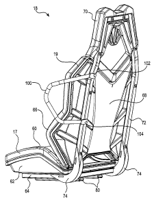
[0062] Turning now to Fig. 4, the left seat 18 will be described in
greater detail. The
right seat is a mirror image of the left seat 18 and for simplicity will not
be described in detail
herein.
4741691.1
CA 02841671 2014-01-27
[0063] As mentioned above, the seat 18 has a seat base 17 and a backrest
19. The seat
base 17 includes a cushion 60 connected on top of a rigid shell 62. A seat
base frame 64 is
fastened to the bottom of the rigid shell 62. The seat base frame 64 is made
of hollow metal
tubes with square cross-sections. The backrest 19 includes a cushion 66
connected in front of
5 a rigid shell 68. The seat 18 also has a headrest 70 disposed above top
part of the cushion 66.
A backrest frame 72 is fastened to the back of the rigid shell 68. The
backrest frame 72 is
made of hollow metal tubes with square cross-sections. The cushions 60 and 66
are concave
so as to provide some lateral support to a rider sitting on the seat 18. The
backrest frame 72
is connected to the seat base frame 64 by a pair of brackets 74. The brackets
74 position the
10 backrest 19 at a fix angle that is slightly greater than 90 degrees. It
is contemplated that the
backrest frame 72 could be connected to the seat base frame 64 by a mechanism
permitting
the adjustment of the angle between the backrest 19 and the seat base 17.
[0064] A seat adjustment mechanism 76 (Fig. 7) is connected between the
seat base
frame 64 and a raised portion 78 of a floor of the cockpit area 22. The seat
adjustment
mechanism 76 allows the seat 18 to be moved forward and backward along a
longitudinal
direction of the RUV 10 between a rearmost position shown in Figs. 5 and 6 and
a
forwardmost position shown in Figs. 7 and 8. The seat 18 can be positioned at
these
positions and at a number of positions intermediate these two positions. The
seat adjustment
mechanism 76 includes a pair of rails 80 (Fig. 4) connected to the bottom of
the seat base
frame 64. The rails 80 are disposed around slide members (not shown) having a
plurality of
holes. Each hole corresponds to a longitudinal position of the seat 18. A
latch member (not
shown) selectively engages one of the holes to set a position of the seat 18.
A lever 82 (Figs.
7 and 8) is connected to the latch member. The lever 82 extends close to a
front of the seat
base 17 so as to be easily actuated by a rider sitting on the seat 18 to
disengage the latch
member so as to allow adjustment of a longitudinal position of the seat 18.
United States
Patent No. 4,726,617, issued February 23, 1988, the entirety of which is
incorporated herein
by reference, describes a seat adjustment mechanism similar to the seat
adjustment
mechanism 76. It is contemplated that other types of seat adjustment
mechanisms could be
used. For example, the seat adjustment mechanism could include an electric
motor that turns
a screw that moves the seat 18 forward or back depending on the direction of
rotation of the
screw. With such a mechanism, the rider sitting on the seat 18 actuates
switches to move the
seat forward or back. The positions of the left and right seats 18 can be
adjusted
independently from each other.
4741691.1
CA 02841671 2014-01-27
11
[00651 A left lateral restraining member 100 is fixed to the left seat
18 so as to be
disposed on a left side thereof. Similarly, a right lateral restraining member
100 is fixed to
the right seat 18 so as to be disposed on a right side of the seat. Therefore,
the lateral
restraining members 100 move forward and back with their respective seats 18.
As can be
seen in Fig. 3, the left lateral restraining member 100 is disposed laterally
between the left
seat 18 and the left lateral restraining member 36. Similarly, the right
lateral restraining
member 100 is disposed laterally between the right seat 18 and the right
lateral restraining
member 36. The lateral restraining members 100 are metal tubes.
[0066] Additional features of the left lateral restraining member 100
will now be
described with respect to the left seat 18 and the left lateral restraining
member 36. As the
right lateral restraining member 100, the right seat 18 and the right lateral
restraining member
36 are mirror images of the left lateral restraining member 100, the left seat
18 and the left
lateral restraining member 36, for simplicity the corresponding features of
the right lateral
restraining member 100 will not be described in detail herein.
[0067] As can be seen in Fig. 4, the upper and lower ends 102, 104 of the
left lateral
restraining member 100 are fixed to the back of a left side tube of the
backrest frame 72 via
fasteners (not shown). It is contemplated that the lateral restraining member
100 could be
fixed to the rigid shell 68 of the backrest 19. The lateral restraining member
100 is disposed
lower than the headrest 70 such that a top of the lateral restraining member
100 is lower than
a top of a shoulder of a 50th percentile North-American adult male sitting on
the seat 18, as
can be seen in Fig. 1. The upper end 102 of the lateral restraining member 100
is disposed
above the vertical center of the backrest 19. In one embodiment, the upper end
102 of the
lateral restraining member 100 is disposed at less than 52 centimeters above a
top rear portion
of the seat base 17. From its upper end 102, the lateral restraining member
100 extends
forwardly, downwardly and laterally outwardly to a point higher than the seat
base 17 and
forward of the backrest 19. From this point, the lateral restraining member
100 extends
rearwardly, downwardly and laterally inwardly to its lower end 104. The lower
end 104 of
the lateral restraining member 100 is disposed below the vertical center of
the backrest 19.
As can be seen, the lateral restraining member 100 is generally U-shaped.
[0068] As best seen in Fig. 6, the lateral restraining member 100 is
smaller than the
lateral restraining member 36. The height of the lateral restraining member 36
is greater than
the height of the lateral restraining member 100. The height of the lateral
restraining
members 36, 100 is measured vertically from their respective vertically lowest
points to their
respective vertically highest points. The length of the lateral restraining
member 36 is greater
4741691.1
CA 02841671 2014-01-27
12
than the length of the lateral restraining member 100. The length of the
lateral restraining
members 36, 100 is measured horizontally from their respective longitudinally
forwardmost
points to their respective longitudinally rearmost points. As can be seen in
Fig. 6, the lateral
restraining member 100 is small enough that when the seat 18 is in its
rearmost position, a
projection of the lateral restraining member 100 on a longitudinally extending
vertical plane
(the drawing page on which Fig. 6 appears corresponding to such a plane) is
disposed
inwardly of a projection of the lateral restraining member 36 on the
longitudinally extending
vertical plane. It is contemplated that the lateral restraining member 100
could be larger than
illustrated. It is also contemplated that the lateral restraining member 100
could be as large
as or even larger than the lateral restraining member 36 in height and/or in
length. Also, as
can be seen in Fig. 5, when the seat 18 is in its rearwardmost position and
the flexible lateral
cover 40 is connected at its forward attachment point 41 so as to extend
across the lateral
passage 24, a front portion of a projection of the lateral restraining member
100 on a
longitudinally extending vertical plane (the drawing page on which Fig. 5
appears
corresponding to such a plane) is outside of a periphery of a projection of
the flexible lateral
cover 40 on this plane.
[0069] As can be seen in Figs. 5 and 6, when the seat 18 is in its
rearmost position, a
majority of the lateral restraining member 36 is disposed forward of the
backrest 19 and a
front end of the lateral restraining member 36 is disposed forward of a front
end of the lateral
restraining member 100. As can be seen in Figs. 7 and 8, when the seat 18 is
in its
forwardmost position, a smaller portion of the lateral restraining member 36
is disposed
forward of the backrest 19 and a front end of the lateral restraining member
36 is disposed
rearward of a front end of the lateral restraining member 100. Also, as can be
seen in Fig. 7,
when the seat 18 is in its forwardmost position and the flexible lateral cover
40 is connected
at its forward attachment point 41 so as to extend across the lateral passage
24, a front portion
(shown in dotted lines) of a projection of the lateral restraining member 100
on a
longitudinally extending vertical plane (the drawing page on which Fig. 7
appears
corresponding to such a plane) overlaps a portion of a projection of the
flexible lateral cover
40 on this plane.
[0070] Modifications and improvements to the above-described embodiment of
the
present technology may become apparent to those skilled in the art. The
foregoing description
is intended to be exemplary rather than limiting. The scope of the present
technology is
therefore intended to be limited solely by the scope of the appended claims.
4741691.1