Note: Descriptions are shown in the official language in which they were submitted.
CA 02841828 2015-10-19
OPTICAL FIBER SENSOR AND METHOD FOR ADHERING AN OPTICAL FIBER TO
A SUBSTRATE
BACKGROUND
[0001] Optical fibers find use in a variety of applications. For example, in
the
drilling and completion industry, optical fibers are utilized to measure
various conditions in a
downhole environment as well parameters of downhole components. Exemplary
optical fiber
sensors include temperature sensors and strain sensors, which can be used to
monitor
deformation in downhole components. For applications such as strain sensing,
it is important
that optical fibers used in sensing be firmly attached or otherwise fixed in
place relative to the
components for which sensing is utilized. In addition, mechanisms for affixing
optical fibers
to substrates must also be able to withstand elevated temperatures and other
conditions
encountered downhole.
SUMMARY OF THE INVENTION
[0002] An optical fiber sensing apparatus comprises a substrate configured to
deform
in response to an environmental parameter; an optical fiber sensor including a
core having at
least one measurement location disposed therein, a cladding, and a protective
coating
surrounding the optical fiber sensor, the protective coating made from a
polyimide material,
the polyimide material adhered directly to an exterior surface of the
cladding; and an adhesive
configured to adhere the optical fiber sensor to the substrate, the adhesive
made from the
polyimide material, a single layer of the polyimide material contacting the
exterior surface of
the cladding and contacting the substrate, the single layer forming both the
protective coating
and the adhesive.
[0003] A method of manufacturing an optical fiber sensing apparatus comprises
disposing an optical fiber sensor on a surface of a substrate configured to
deform in response
to an environmental parameter, the optical fiber sensor including a core
having at least one
measurement location disposed therein, a cladding, and a protective coating
surrounding the
optical fiber sensor, the protective coating made from a polyimide material
that is adhered
directly to an exterior surface of the cladding; and applying the polyimide
material and
bonding the polyimide material to the substrate, the polyimide material
forming a single layer
of the polyimide material contacting the exterior surface of the cladding and
contacting the
substrate, the single layer forming both the protective coating and an
adhesive configured to
adhere the optical fiber sensor to the substrate.
1
CA 02841828 2014-01-09
WO 2013/019337 PCT/US2012/044230
BRIEF DESCRIPTION OF THE DRAWINGS
[0004] These and other features, aspects, and advantages of the present
invention will
become better understood when the following detailed description is read with
reference to
the accompanying drawings in which like characters represent like parts
throughout the
drawings, wherein:
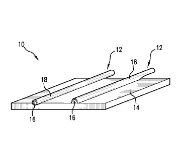
[0005] FIG. 1 is a perspective view of an embodiment of a fiber optic sensing
assembly including a polyimide coated optical fiber sensor adhered to a
substrate;
[0006] FIG. 2 is a cross-sectional view of another embodiment of the fiber
optic
sensing assembly of FIG. 1;
[0007] FIG. 3 is a cross-sectional view of another embodiment of the fiber
optic
sensing assembly of FIG. 1;
[0008] FIG. 4 is a cross-sectional view of an embodiment of an optical fiber
cable
including one or more strain sensing optical fibers;
[0009] FIG. 5 is a cross-sectional view of an embodiment of an optical fiber
cable
including one or more strain sensing optical fibers;
[0010] FIG. 6 is a side cross-sectional view of an embodiment of a downhole
measurement system; and
[0011] FIG. 7 is a flow chart illustrating an embodiment of a method of
manufacturing a fiber optic sensing assembly.
DETAILED DESCRIPTION
[0012] Fiber optic sensors configured for measuring parameters such as strain,
stress
and deformation, as well as other parameters such as temperatures and
pressure, are provided
herein. In one embodiment, such sensors are incorporated in a downhole
assembly for
measuring parameters of components such as downhole tools, borehole strings
and bottom
hole assemblies (BHAs). An exemplary optical fiber sensing assembly includes
an optical
fiber coated with a protective layer made of a polyimide material, which is
adhered to a
substrate via the polyimide material. In one embodiment, the substrate is a
metallic substrate
for which parameters such as strain and deformation are to be measured. The
assembly
includes a deformable member such as a tube that is deformable in response to
pressure
and/or other forces. Such forces include, for example, axial forces and
internal pressures
exerted on the deformable member, e.g., in a downhole environment.
[0013] Referring to FIG. 1, a fiber optic sensing assembly 10 includes an
optical fiber
sensor 12 that is adhered to at least a portion of a substrate 14. In one
embodiment, the
2
CA 02841828 2014-01-09
WO 2013/019337 PCT/US2012/044230
substrate is made from a metallic material such as stainless steel or
aluminum. The substrate
may also be made from other suitable materials including ceramics and plastics
such as
polyetheretherketone (PEEK), Hytrel and polytetrafluoroethylene (PTFE). The
optical fiber
sensor 12 includes an optical fiber 16 having a polyimide coating or outer
layer 18. The
optical fiber sensor 12, in one embodiment, includes an optical fiber 16
having one or more
measurement locations such as fiber Bragg gratings (FBG) located along the
length of the
optical fiber sensor 12. Other measurement units may include lengths or
regions of the
optical fiber sensor 12 utilized for the detection of intrinsic scattering
such as Rayleigh,
Raman or Brillouin scattering signals. The substrate 14 may be any member
deformable by a
force and/or pressure, and need not take the specific shapes and
configurations described
herein. The sensing assembly 10 is configured to estimate various parameters
exerted at
various locations on the substrate 14 and/or the fiber 16. Examples of such
parameters
include external and internal parameters such as strain, pressure and other
forces.
[0014] The optical fiber sensor 12 is adhered to the substrate 14 via a
polyimide
material, which may include the polyimide coating 18 or an additional layer of
polyimide that
is fused to the polyimide coating 18 and adhered to the substrate 14.
Exemplary polyimides
include polyimides having a high glass transition temperature (Tg), such as a
Tg greater than
about 250 degrees C. In one embodiment, the polyimide materials have a Tg that
is greater
than temperatures found in a downhole environment. Examples of such polyimide
materials
include thermoplastic polyimides (TPI) such as PEEK and commercially available
PI-2611
and PI-2525 from HD Microsystems, and composite polyimide materials such as
composite
polyimide/acrylate materials.
[0015] The optical fiber sensor 12 includes a core for transmission of optical
signals,
such as a silica core, and a cladding such as a doped silica cladding. In one
embodiment, the
polyimide coating 18 is adhered directly to the exterior surface of the
cladding. Thus, in this
embodiment, the optical fiber sensor 12 consists of only three layers, i.e.,
the core, the
cladding and a polyimide material that acts as both a protective coating and
an adhesive to
secure the optical fiber sensor 12 in a fixed position relative to the
substrate 14.
[0016] Deformation of the substrate, such as bending, expansion or
contraction,
causes effects such as micro-bends in the optical fiber 16, which in turn
cause a change (e.g.,
a wavelength shift) in the signal returned by the measurement units. This
signal change can
be used to determine the deformation and estimate force and/or pressure based
on the
deformation. The optical fiber sensor 12 may be in communication with a user,
control unit
or other processor or storage device via suitable communication mechanisms.
3
CA 02841828 2014-01-09
WO 2013/019337 PCT/US2012/044230
[0017] FIGS. 2 and 3 illustrates other embodiments of the sensing assembly 10.
In
these embodiments, one or more optical fiber sensors 12 having a polyimide
coating 18 are
adhered via the polyimide coating 18 to a tubular substrate 14. Examples of
the tubular
substrate include sections of a borehole string, such as a drill string or
production string
configured to be disposed in a borehole in an earth formation.
[0018] FIGS. 4 and 5 illustrate exemplary embodiments of a fiber optic cable
20. The
cable 20 may be configured as a strain sensing cable that is disposed with a
deformable
component such as a borehole string or downhole tool to measure parameters
such as strain
and deformation of the component. Other parameters such as temperature and
pressure may
also be measured using the cable 20. For example, all of the embodiments
described herein
can allow for the incorporation of additional optical fibers for other sensing
technologies such
as, but not limited to, distributed temperature sensing (DTS), acoustic
sensing, and single
point pressure/temperature sensing. The exemplary cables 20 described herein
include
multiple optical fiber sensors 12, although the number and configurations of
the optical fiber
sensors 12 are not so limited.
[0019] Referring to FIG. 4, an embodiment of the cable 20 includes one or more
strain sensing optical fiber sensors 12 including fibers 16 that are
encapsulated within and
adhered to metal tubes 22, referred to as "Fiber in Metal Tube" or FIMTs. The
strain sensing
fibers 16 are adhered to the metal tubes 22 via a polyimide coating 18. The
metal tubes 22
are in turn wrapped around or otherwise disposed adjacent to a central member
24. The
central member 24, in one embodiment, is configured as a strength member, such
as a solid
metal or polymer tube. In one embodiment, the central member 24 is configured
to hold
therein additional cable components, such optical fibers for temperature (or
other parameter)
sensing or communication. The central member may also hold other components
such as
copper or other electrically conductive wires or tubes 26. The components of
the cable 20 are
disposed within an outer protective layer 28. In one embodiment, the optical
fiber sensors 12
including the strain sensing fibers 16 have a total outside diameter that is
large enough to
contact components such as the metal tube 22, (e.g., on the order of 300-
400[Lm). In this
embodiment, a large diameter fiber (e.g., about 200[tm) may be used.
[0020] The embodiment shown in FIG. 4 includes FIMT members having the fiber
sensors 12 disposed in the metal tubes 22 and additional wires 30, all of
which are disposed
around the central member 24. However, the cable 20 is not so limited, and may
have
various components and configurations, such as additional optical fibers
disposed in the
metal tubes 22 and/or in the central member 24.
4
CA 02841828 2014-01-09
WO 2013/019337 PCT/US2012/044230
[0021] Referring to FIG. 5, an embodiment of the cable 20 includes one or more
optical fiber sensors disposed on and adhered to a central member or cable
core 32. The
cable core 32 includes passages or grooves 34 extending along the cable core
32 surface, for
example, in an axial or helical path. The fiber optic sensors 12 are disposed
in and adhered to
surfaces of the grooves 34 via their respective polyimide coatings. The cable
core 32 may be
a solid core or may be configured to accommodate additional cable components,
such as the
FIMTs, wires 26 and additional optical fibers. For example, the cable core 32
may have
additional grooves or spaces disposed near its surface, or may be hollow to
accommodate the
additional components.
[0022] The components and configurations of the cables are not limited to the
embodiments described herein. For example, the cables 20 may include other
components
such as additional electrical conductors for supplying power or communication.
Furthermore, the type or configuration of the substrates is not limited.
[0023] Referring to FIG. 6, an exemplary embodiment of a subterranean well
drilling, evaluation, exploration and/or production system 40 includes a
borehole string 42
that is shown disposed in a borehole 44 that penetrates at least one earth
formation 46 during
a subterranean operation. The borehole string 42 includes any of various
components to
facilitate subterranean operations. As described herein, "borehole" or
"wellbore" refers to a
single hole that makes up all or part of a drilled well. As described herein,
"formations" refer
to the various features and materials that may be encountered in a subsurface
environment
and surround the borehole.
[0024] The borehole string 42 includes one or more pipe sections 48 or coiled
tubing
that extend downward into the borehole 44. In one example, the system 40 is a
drilling
system and includes a drill bit assembly. The system 40 may also include a
bottomhole
assembly (BHA). The system 40 and/or the borehole string 42 include any number
of
downhole tools 50 for various processes including drilling, hydrocarbon
production, and
formation evaluation (FE) for measuring one or more physical quantities in or
around a
borehole.
[0025] In one embodiment, the system 40, the tools 50, pipe sections 48, the
borehole
string 42 and/or the BHA include at least one pressure, strain and/or force
sensor, such as the
optical fiber sensor 12 and/or the strain sensing cable 20. The pressure
and/or force sensor is
configured to measure various forces on system components, in the borehole 44
and/or in the
surrounding formation. Exemplary forces include pressure from drilling,
production and/or
borehole fluids, pressure from formation materials, and axial and/or radial
force on
CA 02841828 2014-01-09
WO 2013/019337 PCT/US2012/044230
components of the borehole string 42, tool 50 or other downhole components of
the system
40.
[0026] In one embodiment, the tool 50 and/or optical fiber sensor 12 are
equipped
with transmission equipment to communicate ultimately to a surface processing
unit 52.
Such transmission equipment may take any desired form, and different
transmission media
and connections may be used. The surface processing unit 52 and/or other
components of the
system 40 include devices as necessary to provide for storing and/or
processing data collected
from the optical fiber sensor 12 and other components of the system 40.
Exemplary devices
include, without limitation, at least one processor, storage, memory, input
devices, output
devices and the like.
[0027] FIG. 7 illustrates a method 60 of manufacturing a fiber optic sensing
apparatus. The method 60 includes one or more stages 61-64. Although the
method 60 is
described in conjunction with the optical fiber sensor 12, substrate 14 and
components of the
cable 20, the method 60 is not limited to use with these embodiments. In one
embodiment,
the method 60 includes the execution of all of stages 61-64 in the order
described. However,
certain stages may be omitted, stages may be added, or the order of the stages
changed.
[0028] In the first stage 61, a polyimide coated optical fiber sensor such as
the sensor
12 is disposed on a surface of a substrate that is configured to deform in
response to an
environmental parameter. Examples of the substrate include the substrate 14,
and cable
components such as metal tubes 22, central member 24, wires 30 and cable core
32.
[0029] In the second stage 62, polyimide material making up the coating 18
and/or
additional polyimide material is bonded to the substrate 14. In one
embodiment, a liquid
polyimide is applied to the optical fiber sensor 12 and the substrate is
allowed to harden and
cure (at room temperature or at another selected temperature) to form a bond
between the
optical fiber sensor and the substrate. In one embodiment, polyimide material
making up the
coating 18 and/or additional polyimide material is heated to beyond the glass
transition
temperature of the polyimide material. In one embodiment, only the polyimide
coating 18 is
used and heated. In another embodiment, an additional layer or film is
disposed on the fiber
sensor 12, and both the coating 18 and the additional layer of polyimide is
heated. In yet
another embodiment, the coating 18 is not directly heated, but rather liquid
polyimide is
applied to the fiber 12 and the substrate.
[0030] In the third stage 63, the polyimide material is allowed to cool or may
be
actively cooled to a temperature below the glass transition point. For
example, the polyimide
6
CA 02841828 2014-01-09
WO 2013/019337 PCT/US2012/044230
material is allowed to cool to room temperature. The cooling allows the
polyimide to harden
and bond to the substrate 14.
[0031] In the fourth stage 64, the cooled polyimide is optionally cured for a
period of
time to improve the bond between the polyimide and the substrate. For example,
the
polyimide is heated to an intermediate temperature such as 150 degrees C for a
selected
period of time, e.g., at least about 16 hours.
[0032] There is provided a method of measuring an environmental or component
parameter in a downhole system using the fiber optic sensing assembly 10. In a
first stage,
the optical fiber sensor 12 and/or cable 20 is deployed in the borehole 44 via
the borehole
string 42 and/or via other components, such as a drilling assembly or
measurement sub. In a
second stage, one or more signals are transmitted into the optical fiber
sensor 12. For
example, interrogation signals are transmitted into the optical fiber sensor
12 from the surface
processing unit 52, and measurement locations such as Bragg gratings or
Rayleigh scattering
sections of the optical fiber sensor 12 reflect signals indicative of
parameters such as strain
and deformation.
[0033] The apparatuses and methods described herein provide various advantages
over existing methods and devices. The sensing assemblies provide for
effective strain
sensing at high temperatures, as well as providing a substantially creep-free
bond at high
temperatures. Creep generally refers to degradation or other changes in a
fiber sensor coating
(e.g., adhesive deterioration) that develop over time and affect the detected
wavelength shift
in an optical fiber sensor. Another advantage is provided by the relatively
few number of
types of materials (e.g., a single polyimide material as protective coating
and adhesive),
which minimizes the number of materials used in the sensing apparatus and
hence negates
many material compatibility challenges that could arise.
[0034] In connection with the teachings herein, various analyses and/or
analytical
components may be used, including digital and/or analog systems. The apparatus
may have
components such as a processor, storage media, memory, input, output,
communications liffl(
(wired, wireless, pulsed mud, optical or other), user interfaces, software
programs, signal
processors (digital or analog) and other such components (such as resistors,
capacitors,
inductors and others) to provide for operation and analyses of the apparatus
and methods
disclosed herein in any of several manners well-appreciated in the art. It is
considered that
these teachings may be, but need not be, implemented in conjunction with a set
of computer
executable instructions stored on a computer readable medium, including memory
(ROMs,
RAMs), optical (CD-ROMs), or magnetic (disks, hard drives), or any other type
that when
7
CA 02841828 2014-01-09
WO 2013/019337 PCT/US2012/044230
executed causes a computer to implement the method of the present invention.
These
instructions may provide for equipment operation, control, data collection and
analysis and
other functions deemed relevant by a system designer, owner, user or other
such personnel, in
addition to the functions described in this disclosure.
[0035] While the invention has been described with reference to exemplary
embodiments, it will be understood by those skilled in the art that various
changes may be
made and equivalents may be substituted for elements thereof without departing
from the
scope of the invention. In addition, many modifications will be appreciated by
those skilled
in the art to adapt a particular instrument, situation or material to the
teachings of the
invention without departing from the essential scope thereof. Therefore, it is
intended that
the invention not be limited to the particular embodiment disclosed as the
best mode
contemplated for carrying out this invention.
8