Note: Descriptions are shown in the official language in which they were submitted.
CA 02841845 2014-01-09
WO 2013/007806 PCT/EP2012/063747
- 1 -
Liquid Container
The present invention relates to a container for liquids, a method of filling
it and the
use of the container according to the invention for holding and storing
materials
such as radioactive materials, particularly radioactive material for
therapeutic and/or
diagnostic purposes.
Containers for holding and storing liquids are everyday objects. In the
chemical or
medical field, glass bottles that are closed by means of screw caps, crimped
closures, stoppers or flanged caps have been successful as storage means for
liquids.
Glass bottles have the advantage of being inexpensive, easy to sterilise and
inert in
the presence of a large number of liquids.
Published German application DE19739139A1 describes by way of example a
small volume container made of glass for medical purposes.
Published applications W01 992/00889A1, W01993/1 1053A1 and
W01995/04685A1 disclose a container with a combined flanged and snap-on lid
closure.
When filling glass bottles with liquids it may happen that drops of the liquid
accidentally land on the edge of the bottle or on the outer wall of the
bottle. In the
case of liquids that constitute a danger to people and/or the environment this
is a
problem. It is essential to ensure that hazardous substances do not
accidentally
enter the environment. This applies particularly to radioactive substances.
Radioactive substances are used in medicine for diagnostic and therapeutic
purposes. Diagnostic processes in which radioactive compounds are used for
example to produce sectional images of living organisms include SPECT (Single
Photon Emission Computed Tomography) and PET (Positron Emission
Tomography). Substances that emit alpha particles are used for example in
treating tumours (radiotherapy).
,
81776384
- 2 -
In the medical field, in particular, contamination of the glass outer wall
when filling glass
bottles with radioactive substances must be prevented as the glass bottles are
handled
by hospital staff.
The present invention solves the problem of contamination by providing a new
container
and a method of filling the new container. The invention further relates to
the use of the
container according to the invention for holding and storing radioactive
compounds,
particularly radioactive substances for therapeutic and/or diagnostic
purposes.
Thus in a first aspect the present invention relates to a container for a
liquid, containing
at least
- a cavity for holding the liquid, the cavity being bounded by walls at the
sides
and at the bottom,
- an opening for filling the cavity with the liquid,
- a closure for closing off the cavity, the closure having a
piercing region for
inserting a cannula into the cavity,
- a bottom casing which surrounds the walls of the cavity in the standing
area,
- a top casing which surrounds the pierceable closure with the
exception of the
piercing region, and
- a film which extends from the top casing to the bottom casing
and surrounds
those areas of the walls of the cavity which are not already surrounded by the
top casing or bottom casing.
Thus, in another aspect the present invention relates to a container for a
liquid,
comprising a cavity for holding the liquid, the cavity being bounded by walls
at the sides
and at the bottom, an opening for filling the cavity with the liquid, a
closure for closing off
the cavity, the closure having a piercing region for inserting a cannula into
the cavity, a
bottom casing which surrounds the walls of the cavity at the base of the
cavity, a top
casing which surrounds the closure with the exception of the piercing region,
and a film
which extends from the top casing to the bottom casing, joining the bottom
casing and
CA 2841845 2018-11-02
81776384
- 2a -
top casing together, and surrounds the areas of the walls of the cavity which
are free of
the top casing or bottom casing; wherein the film is adhesively bonded to the
top casing,
the bottom casing, and the walls; wherein the walls of the cavity and the
closure form an
inner shell constituting a primary vessel, and wherein the bottom casing, top
casing, and
film together enclose any surface contamination on the primary vessel.
Thus, in another aspect the present invention relates to use of a container as
described
herein, for holding and storing a radioactive substance.
The container according to the invention has an inner and outer shell. The
inner shell
surrounds a cavity which serves to hold a liquid. The inner shell thus
constitutes a
primary vessel into which a liquid can be placed and in which the liquid is
stored.
The outer shell surrounds the inner shell. The outer shell is only applied
after the cavity
has been filled. The outer shell is intended to enclose any residues of
liquids
CA 2841845 2018-11-02
CA 02841845 2014-01-09
WO 2013/007806 PCT/EP2012/063747
- 3 -
that have accidentally reached the outside of the inner shell during filling,
so that
these residues cannot form a handling or health hazard or enter the
environment.
According to the invention the inner shell is formed by walls and a closure.
The
walls delimit the cavity for holding the liquid at the sides and at the
bottom. At the
top the cavity is not delimited, i.e. an opening is located here for filling
the cavity
with a liquid.
Any directional information in the present description relates to the
direction of
gravity. The term "downwards" means in the direction of gravity. The term
"upwards" means in the opposite direction to gravity. Terms such as "lateral"
or "to
the sides" indicate a direction perpendicular to the direction of gravity.
The walls consist of a material that is impervious to the liquid used and
which is not
attacked by the liquid used. The man skilled in materials science will be
aware of
the materials that are suitable for particular liquids.
Preferred materials are glasses or plastics as these are inert to a large
number of
different liquids, i.e. are not attacked. However it is also possible for the
walls to
consist of metal, for example. For aqueous solutions, glasses and plastics are
particularly suitable, for example polymers such as polyolefins (e.g.
polyethylene,
polypropylene) or polyesters (e.g. polyethylene terephthalate, polycarbonate).
Composite materials are also possible.
In a preferred embodiment a silicate glass is used of the kind conventionally
used
for storing aqueous chemicals. Such glasses are sold by companies such as
Schott AG, for example.
As the container according to the invention is preferably intended to hold
single
doses of drugs or diagnostic agents, the cavity preferably has a volume of
from 1 ml
to 200 ml. Particularly preferably, the cavity has a volume of from 2 ml to
100 ml,
most preferably from 5 ml to 30 ml.
The walls that bound the cavity for holding a liquid form a primary vessel
which may
be in the shape of a hollow cylinder in the lower region (particularly
externally),
CA 02841845 2014-01-09
WO 2013/007806
PCT/EP2012/063747
- 4 -
according to a preferred embodiment. The hollow cylinder typically tapers
upwards,
towards the opening, so that the primary vessel may have the shape of a
shoulder
and/or neck which are typical of many liquid containers. At the end of the
neck
there is preferably a flange that runs around the opening of the primary
vessel and
is used for attaching the closure. Other methods of attaching a closure (eg
adhesively) may be used equivalently, as will be clear to those of skill in
the area.
A preferred primary vessel of this kind is shown by way of example in Figure
1.
After filling, the cavity is closed off. Therefore the container according to
the
invention has a closure (e.g. shown as 40 and 43 in Figure 4) which is placed
over
the fill opening (e.g. 5 in Figure 1) when the cavity is closed.
The closure and the primary vessel are embodied such that the liquid cannot
accidentally escape from the sealed primary vessel. Usually a seal is used
such as
a sealing ring (0-ring), e.g. made of synthetic rubber. The choice of material
for the
seal will depend, among other things, on the liquid used and the materials
used for
the primary vessel and closure. The man skilled in materials science will know
which materials are suitable and many options are readily available to the
skilled
worker.
In a preferred embodiment the closure has an apron with which the closure can
be
secured on the flange of the primary vessel in the manner of a snap-on lid
closure
or a flanged closure.
The closure is preferably configured to be pierceable. This means that a
cannula
can be pushed through the closure to insert it into the cavity and remove
liquid. For
this purpose the closure has at least one region through which a cannula can
be
pushed. This region is referred to here as the piercing region. The term
"cannula"
is used herein to indicate any hollow piercing element suitable for the
withdrawal or
transfer of liquids. This will include any hollow needle, cannula, tube or
similar
device formed of metal, plastic or any suitably rigid material.
For example, the closure used may be a flanged aluminium cap with a
silicon/PTFE
septum or a septum made of synthetic rubber, as is generally conventional in
CA 02841845 2014-01-09
WO 2013/007806 PCT/EP2012/063747
- 5 -
injection ampoules in the medical field (PTFE = polytetrafluorethylene, the
PTFE
layer is on the side facing the liquid).
The container according to the invention further comprises a bottom casing.
The
bottom casing surrounds the walls of the cavity at its base. In other words:
the
primary vessel sits into the bottom casing. The bottom casing forms a kind of
shoe
for the primary vessel. It protects the primary vessel at its base and also
ensures
its stability.
The joint between the primary vessel and the bottom casing may be formed in
various ways. For example, it is possible for the bottom casing to be
frictionally or
interlockingly connected to the primary vessel and/or joined with a suitable
adhesive. It is possible for the bottom casing and the primary vessel each to
have
a thread which allows the primary vessel and bottom casings to be screwed
together. Preferably the bottom casing is frictionally connected to the
primary
vessel.
In addition to the bottom casing the container according to the invention has
a top
casing. The top casing surrounds the pierceable closure, the piercing region
being
excluded from the covering such as by means of an opening in the top casing.
In a
preferred embodiment the top casing has an opening of the same (or
substantially
the same) size as the piercing region, positioned so as to be aligned with the
piercing region after the top casing and closure have been joined together.
The top
casing may also surround upper parts of the primary vessel.
The connection between the closure and top casing may take various forms. For
example, it is possible for the top casing to be frictionally or
interlockingly connected
to the closure (and optionally to the primary vessel) and/or connected by
means of
an adhesive. It is possible for the top casing and the closure to have threads
which
allow the components to be screwed together. Preferably, the top casing is
frictionally connected to the closure.
The bottom and top casing preferably consist of an elastic material capable of
cushioning impact. If the vessel is made of glass, for example, which is known
to
CA 02841845 2014-01-09
WO 2013/007806 PCT/EP2012/063747
- 6 -
be brittle and hence comparatively easy to break, the bottom and top casing
preferably provide impact protection in the bottom and top regions of the
vessel.
Preferably the bottom and top casing consist of a plastic such as for example
a
synthetic rubber or a thermoplastic. Composite materials may also be used. The
bottom and top casing may be made of the same or different materials.
Preferably,
they are made of the same materials. Examples of preferred materials include
polymers such as polyolefins (e.g.; polyethylenes, polypropylenes) or
polycarbonate.
In a particularly preferred embodiment the primary vessel has the external
shape of
a hollow cylinder in its lower region. The bottom casing consists of an
elastic
material and is adapted to the shape of the primary vessel. In a preferred
embodiment, the internal diameter of the bottom casing being somewhat smaller
than the external diameter of the primary vessel in the lower region (e.g.
having an
internal diameter 0.5% to 10% smaller than the external diameter of the
primary
vessel in the lower region). The bottom casing is pushed over the lower part
of the
primary vessel in order to attach it; the elastic material expands and
provides a
frictional connection between the bottom casing and primary vessel.
The internal shape of the primary vessel may, in an optional embodiment,
differ
from the external shape of the primary vessel, especially in the lower region.
In
particular, the primary vessel may taper internally to aid the removal of
small
volumes of liquid from the container (e.g. at the end of fluid withdrawal).
This can
be achieved by varying the thickness of the walls at the sides and bottom
(e.g. parts
3 and 2 respectively in Figure 1) so as to achieve an internal taper while
maintaining a substantially cylindrical external shape in the lower region.
Analogously, a preferred connection is made between the top casing and the
closure: the closure is of cylindrical configuration; the top casing consists
of an
elastic material and is adapted to the shape of the closure. In a preferred
embodiment, the internal diameter of the top casing being somewhat smaller
than
the external diameter of the closure(e.g. having an internal diameter 0.5% to
10%
smaller than the external diameter of the closure). The top casing is pushed
over
the closure to secure it; the elastic material thus expands and provides a
frictional
CA 02841845 2014-01-09
WO 2013/007806
PCT/EP2012/063747
- 7 -
connection between the top casing and the closure. For the man skilled in
materials and connection technology it is obvious how the bottom casing, top
casing, primary vessel and closure have to be configured to enable the primary
vessel to be pushed into the bottom casing and the top casing to be pushed
onto
the closure without the bottom and top casing slipping off again.
The connection of the bottom and top casing to the primary vessel and closure
do
not have to be particularly solid as the components are also fixed by means of
a
film (see below). The connection should moreover be at least precisely strong
enough to prevent the bottom and top casing from slipping off. It is important
that
the components should be capable of being joined together easily. The filling
process should in principle be capable of automation. For rapid and
frictionless
operation it is important that the primary vessel should be fitted easily into
the
bottom casing and that the top casing should be fitted easily onto the
closure.
The bottom casing and top casing also provide areas for connection by means of
a
film.
In a preferred embodiment the top casing is in the form of a telescopic
cylinder with
an upper, tapering portion and a lower, widened portion. A top casing of this
type is
shown by way of example in Figure 5. The tapered portion is fitted over the
closure
and provides a frictional connection. The widened portion surrounds the neck
and
shoulder of the primary vessel and fits flush against the cylindrical belly
region of
the primary vessel. This preferred embodiment produces a bottle which is very
suitable for attachment with the film or foil.
The film of the container according to the invention extends between the
bottom
casing and the top casing and joins them together. The film surrounds the
areas of
the primary vessel that are not already surrounded by the bottom or top casing
(save that it does not typically cover and opening in the top casing that
aligns with
the piercing region of the closure). The connection of the film to the bottom
casing,
top casing and primary vessel is preferably carried out by means of a layer of
adhesive. However, it is also possible to shrink-fit the film onto the bottom
casing,
top casing and primary vessel. The film provides mechanical stabilisation of
the
assembly of primary vessel, closure, bottom casing and top casing. The film
safely
CA 02841845 2014-01-09
WO 2013/007806 PCT/EP2012/063747
- 8 -
encloses any contaminants that have got onto the outer wall of the primary
vessel
during the filling of this vessel. The assembly of bottom casing, top casing
and film
constitutes a second skin for the primary vessel and thereby on the one hand
protects the primary vessel and its contents from external influences but also
provides protection for the environment in case the primary vessel breaks and
the
liquid threatens to escape from the primary vessel. This is in addition to
enclosing
any surface contamination and thus reducing the risk posed thereby.
Therefore, the film preferably consists of a material which, like the primary
vessel, is
not attacked by the liquid. Examples of preferred materials are polymers such
as
polyolefins (e.g. polyethylene, polypropylene) or polyesters. Composite
materials
are also possible.
In one embodiment, the film is of sufficient size to wrap completely around
the
eternal circumference of the primary vessel (and preferably also of the top
and
bottom castings). Thus, the film may additionally be sized to be longer than
the
external circumference of the primary vessel such that an overlap exists
whereby
the film laps over itself. In this embodiment the film may secure at least
partially to
itself, for example by means of an adhesive. By providing a film of at least
the size
of the circumference of the primary vessel, the external side walls of the
vessel may
be completely encapsulated with corresponding encapsulation of any surface
contamination. Any overlap may be, for example, 1% to 50% of the circumference
of the primary vessel.
In a preferred embodiment the container according to the invention
additionally has
a sealing film. This seals the opening of the top casing over the piercing
region.
The sealing film is preferably adhesively bonded to the top casing. The
sealing film
may be designed so that it can be completely or at least partially removed
again to
provide access to the piercing region. Alternatively the sealing film may also
be
pierced by the cannula.
The container according to the invention is suitable for the storage and
transporting
of different liquids. Preferably, it is used for liquids which represent a
danger to
people or the environment.
CA 02841845 2014-01-09
WO 2013/007806
PCT/EP2012/063747
- 9 -
The present invention further relates to the use of the container according to
the
invention for storing radioactive substances, particularly radiotherapeutic
and/or
diagnostic agents, most preferably substances that emit alpha particles.
Preferably
the container according to the invention holds a single dose for the treatment
of a
human being or animal or for diagnostic use in a human or animal.
The container of the invention (and all other aspects) is particularly suited
to use
with liquids containing alpha-emitting radionuclides. This is because such
alpha-
emitting radionuclides are hazardous and/or toxic and subject to strict
controls but
alpha radiation is readily stopped by materials such as plastics which are
suitable
for the formation of the top and bottom casings and films referred to herein.
Thus
hazards for alpha-emitting radionuclides are effectively avoided or limited by
encapsulation of any surface contamination by the methods described herein.
The preferred embodiments mentioned above for the containers according to the
invention also apply analogously to the use according to the invention.
Before the use of the novel container a liquid is first placed in the primary
vessel. It
is possible for the primary vessel to be sterilised before being filled. The
skilled
man in the field of medicine and sterilisation technology will be familiar
with suitable
methods, of which so-called autoclaving is mentioned here by way of example.
After filling, which is preferably carried out automatically using
corresponding
pipetting robots, the primary vessel is sealed in fluidtight manner - again
preferably
automatically - with a pierceable closure.
It is possible to carry out sterilisation, e.g. by autoclaving, after the
sealing process.
It is conceivable that during the filling or sealing of the primary vessel or
during any
sterilisation process contamination may occur to the outer wall of the primary
vessel. It is possible, for example, that a drop of the liquid will land on
the edge of
the primary vessel opening during filling and tiny amounts of the liquid will
not be
sealed in the primary vessel during sealing but will remain between the
primary
vessel and the closure, so that there is a risk of these amounts entering the
environment. In the case of radioactive substances (such as alpha-emitting
CA 02841845 2014-01-09
WO 2013/007806 PCT/EP2012/063747
- 1 0 -
radionuclides), in particular, it is absolutely essential to prevent
contamination of the
environment.
Therefore after filling and sealing and sterilisation, if applicable, the
container
according to the invention is enveloped: the primary vessel is provided with a
bottom casing, the closure is provided with a top casing, the remainder of the
primary vessel is provided with a film which is also covered by parts of the
top and
bottom casings and optionally a sealing film is placed over the piercing
region.
The present invention thus also includes a method of filling the container
with a
liquid. The method according to the invention comprises at least the following
steps:
- filling a primary vessel with a liquid (e.g. a liquid containing at least
one toxic and/or hazardous substance such as an a radionuclide),
closing the filled primary vessel,
- providing the primary vessel with a bottom casing at the base,
- providing the closure with a top casing,
- enveloping those parts of the primary vessel that are not already
enclosed by the bottom casing or top casing with a film, the film
extending from the bottom casing to the top casing and joining these
together (save that any opening in the top casing may be left un-
encapsulated or may be encapsulated by a further sealing film).
The preferred embodiments mentioned above for the container according to the
invention also apply analogously to the method according to the invention.
In a preferred embodiment of the method according to the invention the film
that
has an adhesive layer on one side is wrapped around the primary vessel to
attach it
to the primary vessel. The process is preferably automated. The film is
preferably
a transparent or substantially transparent film. This allows that the contents
of the
container may remain visible.
In a further embodiment, the invention provides for a method for reducing a
hazard
from radiation emanating from surface contamination of a primary vessel
containing
at least one radioisotope comprising:
CA 02841845 2014-01-09
WO 2013/007806
PCT/EP2012/063747
-11-
- closing the filled primary vessel,
- providing the primary vessel with a bottom casing in the standing
area,
- providing the closure with a top casing,
enveloping those parts of the primary vessel that are not already
surrounded by the bottom casing or top casing with a film, the film
extending from the bottom casing to the top casing and connecting
them to each other.
Such a hazard may be any hazard associated with radionuclides and particularly
alpha-radionuclides, such as a handling hazard, a contamination hazard, and/or
and environmental hazard. All embodiments and definitions described herein may
be applied to this aspect of the invention, where context permits, especially
those
described herein as preferred.
The invention, in a further aspect provides for the use of a top casing, a
bottom
casing and a film extending from the bottom casing to the top casing to
reducing a
hazard from radiation emanating from surface contamination of a filled primary
vessel containing at least one radioisotope.
Such a hazard may be any hazard associated with radionuclides and particularly
alpha-radionuclides, such as a handling hazard, a contamination hazard, and/or
and environmental hazard. All embodiments and definitions described herein may
be applied to this aspect of the invention, where context permits, especially
those
described herein as preferred.
A preferred embodiment will now be described in more detail, for further
explanation of the invention, but without restricting the invention to this
embodiment.
Example
A container was produced from the following components:
CA 02841845 2014-01-09
WO 2013/007806
PCT/EP2012/063747
- 12 -
Primary
vessel: 10 ml clear glass specimen vessel (e.g. vial) or a 10 ml
injection
ampoule made of clear glass, glass type I (ISO 719 or ISO 720),
manufactured according to the European Pharmacopoeia.
Closure: Flanged aluminium cap with rubber stopper.
Top cap: Injection moulded part made of polypropylene (BormedTmHF840M0
made by Borealis AG).
Bottom cap: Injection moulded part made of polypropylene (BormedTmHF840M0
made by Borealis AG).
Film: Stralfors Label Material LR2240 (Stralfors AG), self-adhesive
composite material consisting of a transparent polyolefin film and an
acrylic adhesive.
Figures 1-5 show the container produced and its components.
In the figures:
Figure 1 shows the primary vessel in cross-section from the side
Figure 2 is a perspective view of the container according to the
invention
Figure 3 shows the container according to the invention from the side
Figure 4 shows the container according to the invention in cross-section
from
the side
Figure 5 shows the top casing of a container according to the
invention
Figure 6 shows the bottom casing of a container according to the
invention
Figure 1 shows a preferred embodiment of a primary vessel in cross-section. A
lower wall (2) and side walls (3) enclose a cavity (4). The cavity can be
filled with
liquid through an opening (5). The primary vessel has the shape of a hollow
cylinder in the lower region and in the belly region. The hollow cylinder
tapers
upwards; a shoulder (6) and a neck (7) are formed. Around the opening (5) is a
flange (8) to which a closure can be attached.
CA 02841845 2014-01-09
WO 2013/007806
PCT/EP2012/063747
- 13 -
Figure 2 shows a container according to the invention in perspective view. The
drawing shows the top casing (10) which has an opening. Underneath the opening
can be seen the piercing region (45) of the closure. Also shown are the bottom
casing (20) and the film (30) that extends between the top casing and bottom
casing.
Figure 3 shows a container according to the invention from the side. The
drawing
shows the top casing (10), the bottom casing (20) and the film (30) that
adhesively
connects the top and bottom casings to one another.
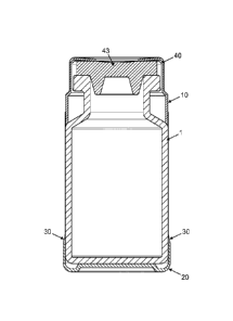
Figure 4 shows a container according to the invention in cross-section from
the
side. A primary vessel (1) is closed off by a septum (43) and a flanged
aluminium
cap (40). Over the closure is placed a top casing (10) that is frictionally
connected
to the flanged aluminium cap. The top casing widens out downwardly. It lies
flush
against the outer primary vessel wall. The bottom casing (20) is frictionally
connected to the primary vessel (1) at its base. Around the primary vessel is
wrapped a film (30) that extends between the top and bottom casings.
Figure 5 shows the top casing of the novel container shown in Figures 2-4 (a)
from
the side, (b) in cross-section from the side, (c) viewed from above and (d) in
perspective view. The top casing has a widened region (12) and a tapering
region
(14); a shoulder (13) joins the regions together.
Figure 6 shows the bottom casing of the novel container shown in Figures 2-4
(a)
from the side, (b) in cross-section from the side, (c) viewed from above and
(d) in
perspective view.